

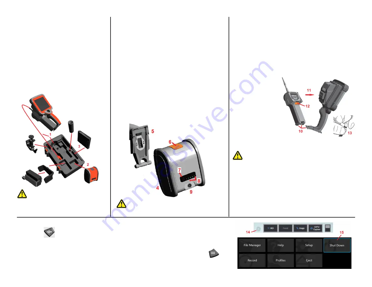
Unpacking the Visual iQ System
1
– The insertion tube (shown in red for clarity)
is held in the case’s internal storage reel, which
is accessed through the orange funnel. Install the
insertion tube before installing the probe-and-
handset assembly and remove it after removing the
probe-and-handset assembly. Be sure to straighten
any loops or twists in the insertion tube before
feeding it into the funnel. Note that the insertion
tube’s rubber Torsional Strain Relief base should be
routed through the case’s curved passage.
2
–
Battery must be removed prior to installing the
iQ in the case.
3
–
A case holding tips (or cleaning kit) fits in this slot.
Installing the Battery
Note: All batteries are shipped with a partial charge. Batteries
should be fully charged prior to use.
Insert the battery into the handset. The battery is installed
properly when the latching mechanism is engaged. Do not
force the battery (
4
) into the handset (
5
), as damage may occur.
The battery is keyed and may only be installed in the proper
orientation.
Removing the Battery
Press battery release button (
6
) to release the battery.
Battery Charge Level
Check the battery charge by pressing the battery symbol (
7
) on
the front of the battery. Each light (
8
) represents approximately
20% of the battery charge capacity. Connect the DC output of
the battery charger into the Visual iQ battery (
9
) and then plug
the included AC to DC power adaptor into a suitable AC power
source. The LED battery lights will illuminate according to the
amount of charge attained and will turn off when fully charged.
The system may operate while charging.
Attaching and Removing the Probe and Optical Tips
10
– Insert the pin at the base of the handset into the mating groove
at the bottom of the probe.
11
– Rotate the probe towards the back of the handset, applying
enough pressure for the latching mechanism to “click.”
12
– Press this latching-mechanic's release button to separate the
probe and handset.
13
– Optical tips are threaded onto the probe with a double set of
threads to prevent them from falling into the inspection area.
To Attach an Optical Tip:
Verify that the optical tip
and camera head threads
are clean, then grasp the
head of the probe with
one hand, and with the
other gently turn the tip
clockwise. Turn until it
spins freely, indicating
that it has cleared the
first set of threads. Gently
push the tip in, then turn
clockwise again, engaging
the second set of threads.
Turn until finger tight.
Powering the Visual iQ On and Off
Press and hold
until the unit turns on. The buttons and Liquid Crystal Display (LCD) will light and begin the power-up
sequence. After approximately 45 seconds, the system screen will display live video and on-screen controls. The system
is now ready for use.
Touch the lower left corner of the display screen (which typically contains the on-screen GE Logo (
14
) or the
hard
key at any time to open or close the Global Menu, which provides access to several features including Shut Down (
15
).
Select Shut Down to power off the Visual iQ.
Caution: Do not remove the battery while the system
is operating.
Caution: Before using the camera system,
always install an optical tip or the head guard.
Caution: Use only finger pressure to remove or attach tips.
Using force (including pliers or other tools) might damage the bending
neck. Take care not to cross the threads. To reduce cross-threading
risk: When installing a tip by hand (6.1mm & 8.4mm) or with an
installation tool (4mm), rotate the tip counter clockwise to level the
threads before rotating clockwise to thread the tip on the camera.
Reverse the leveling process when removing tips.
MVIQAQSG Rev. C


