background image

GE Oil & Gas

Masoneilan* SVI* FF Digital Positioner

Quick Start Guide

(Rev.

 D)

GE Data Classification: Public

Summary of Contents for Masoneilan SVI FF

Page 1: ...GE Oil Gas Masoneilan SVI FF Digital Positioner Quick Start Guide Rev D GE Data Classification Public ...

Page 2: ...ERATORS ALREADY HAVE A GENERAL UNDERSTANDING OF THE REQUIREMENTS FOR SAFE OPERATION OF MECHANICAL AND ELECTRICAL EQUIPMENT IN POTENTIALLY HAZARDOUS ENVIRONMENTS THEREFORE THESE INSTRUCTIONS SHOULD BE INTERPRETED AND APPLIED IN CONJUNCTION WITH THE SAFETY RULES AND REGULATIONS APPLICABLE AT THE SITE AND THE PARTICULAR REQUIREMENTS FOR OPERATION OF OTHER EQUIPMENT AT THE SITE THESE INSTRUCTIONS DO N...

Page 3: ...ooters Made a few changes to Quick Start section Changed ES 776 to Rev J C 02 15 Changed ES 776 to Rev K and to Declaration of Conformity D 03 17 Changed ES 776 to Rev L 2017 General Electric Company All rights reserved Masoneilan SVI FF Positioner Quick Start Guide 3 ...

Page 4: ...This page intentionally left blank ...
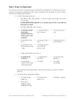
Page 5: ...ety Symbols Indicates a potentially hazardous situation which if not avoided could result in serious injury or death Indicates a potentially hazardous situation which if not avoided could result in instrument or property damage or data loss Indicates important facts and conditions WARNING CAUTION NOTE 1 SVI FF Quick Start ...

Page 6: ...ent the dropping of tools or equipment during installation Under normal operation compressed supply gas is vented from the SVI FF to the surrounding area and may require additional precautions or specialized installations Intrinsically Safe Installation Products certified as explosion proof or flame proof equipment or for use in intrinsically safe in stallations MUST BE Installed put into service ...

Page 7: ...ich may lead to personal injury or death Installation in poorly ventilated confined areas with any potential of gases other than oxygen being present can lead to a risk of personnel asphyxiation Use only genuine replacement parts which are provided by the manufacturer to guarantee that the products comply with the essential safety requirements of the European Directives Changes to specifications s...

Page 8: ... the bracket that is mounted to the valve actuator 4 Connect the pneumatic tubing to the SVI FF 5 Connect the air supply to the SVI FF 6 Connect the positioner to the H1 segment by installing the SVI FF wiring 7 Configure calibrate using ValVue the SVI FF DTM or a handheld using the DD See Example Configuration on page 13 for a general example WARNING Failure to adhere to the requirements listed m...

Page 9: ...he menu structure to the previous item in the menu or decrement the value currently shown in the digital display When used to decrease a displayed value holding the button down causes the value to decrease at a faster rate Right Button Marked permits you to move forward through the menu structure to the next item in the menu or to increment the value currently shown in the digital display When use...

Page 10: ...ion Table 2 Travel Sensor Alignment Rotary Mounting System Stroke Direction Magnet Orientation Valve Position Sensor Counts TB RAW_POSITION Rotary 60 Rotation Clockwise or counter clockwise rotation 0 Closed 0 0 1000 60 Rotation Clockwise with increas ing setpoint 45 Full Open or Full Closed 8000 1500 or 8000 1500 60 Rotation Counter Clockwise rota tion with increasing set point 45 Full Open or Fu...

Page 11: ...ke Mounting Hole Lever Hole Turnbuckle Length 6 and 10 0 5 0 8 12 7 20 32 mm A A 1 25 31 75 mm 10 0 5 0 8 12 7 20 32 mm A A 1 25 31 75 mm 10 0 8 1 5 20 32 41 5 mm B B 1 25 31 75 mm 16 0 5 0 8 12 7 20 32 mm B A 2 90 73 66 mm 16 0 8 1 5 20 32 41 5 mm C B 2 90 73 66 mm 16 1 5 2 5 41 5 63 5 mm D C 2 90 73 66 mm 23 0 5 0 8 12 7 20 32 mm B A 5 25 133 35 mm 23 0 8 1 5 20 32 41 5 mm C B 5 25 133 35 mm 23 ...

Page 12: ...re 1 Connections to Electronics Module via Terminal Board Display Remote I P Connector Position Sensor Configuration Lock Jumper 9 32 V Foundation Discrete Out Input Discrete Shield on FF unit Input Signal polarity independent Input Fieldbus housing AI PV 1 5 VDC Not used in this release ...

Page 13: ...er a Device Address and Device Tag Step 2 Set Control Tuning by choosing Single or Double Acting and setting tuning type Autotune is recommended Custom requires entering your values Step 1 Set Air Action Step 3 Set Characterization Type Custom requires entering your values Step 5 Run Find Stops and then run Autotune Figure 2 Quick Start Configuration Example Configuration Step 1 Install the Positi...

Page 14: ... Set Address follow the prompts to enter an Address 5 Click Set Do not navigate to the NI DD folder and copy the DD file onto itself Do not deactivate the Set to OOS mode checkbox The block must be in OOS to change the Tag If the device is at the temporary address range 248 0xF8 251 OxFB you must set the address outside of that range Do not deactivate the Set to OOS mode checkbox The block must be...

Page 15: ... is used ACTIVATE_CONTROL_SET to one of 0 Activate Custom Control Set required for Auto tune as well most common 1 Activate Control Set 1 Slowest 2 Activate Control Set 2 3 Activate Control Set 3 4 Activate Control Set 4 5 Activate Control Set 5 Fastest 6 Activate Control Set 6 Double Acting Slow 7 Activate Control Set 7 Double Acting Fast CHAR_SELECTION TYPE to one of 0 Linear most common 1 Equal...

Page 16: ... DD SVI FF local pushbuttons or software to run METHOD Step 5 Run Auto Tune METHOD Use a configuration tool DD SVI FF local pushbuttons or software to run METHOD Downloads To download the complete user manual DD SVI FF Advanced DTM and the ValVue Suite trial pro gram visit https www geoilandgas com file download search ...

Page 17: ...S 776 Rev K D ADR 003896 Oct 1 2013 E ADR 003908 Nov 6 2013 F ADR 003913 Jan 8 2014 G ADR 003926 Feb 24 2014 H ADR 003933 May 6 2014 J ADR 003987 Dec 16 2014 K ADR 004000 Jan 16 2014 L PDR ECO 0026891 Oct 28 2016 Page 1 of 14 Copyright 2016 This document and all information herein is the property of Dresser Inc ES 776 SPECIAL INSTRUCTIONS FOR INSTALLING Masoneilan SVI FF POSITIONER IN AREAS WHERE ...

Page 18: ...NTRINSICALLY SAFE REQUIREMENTS 7 Div 2 7 5 1 Category II 1 Zone 0 7 5 2 Category II 1 Zone 0 7 5 3 Internal pollution degree 2 and overvoltage category III 7 5 4 6 DESCRIPTION OF FLAMEPROOF AND INTRINSICALLY SAFE MARKINGS 8 7 INTRINSICALLY SAFE INSTALLATION WIRING REQUIREMENTS 10 8 NOTES FOR INTRINSICALLY SAFE INSTALLATION 11 HAZARDOUS LOCATION 11 8 1 FIELD WIRING 11 8 2 Foundation Fieldbus IN and...

Page 19: ...es that the SVI FF positioner will not cause ignition of the surrounding atmosphere Hazards related to control of the process are beyond the scope of this manual For mounting instructions on specific valves refer to the mounting instructions supplied with the mounting kit Mounting does not affect the suitability of the SVI FF positioner for use in a potentially hazardous environment For language t...

Page 20: ...ing is a die casting alloy which is predominately aluminum X Marking is on label Before powering the SVI FF positioner Verify that the pneumatic and electronic cover screws are tightened This is important to maintain the ingress protection level and the integrity of the flameproof enclosure If the Installation is Intrinsically safe then check that the proper barriers are installed and the field wi...

Page 21: ...c FM GOST 3 Advanced Diagnostics No Display No Buttons Stainless Steel KOSHA 4 Display Buttons Stainless Steel NEPSI 5 INMETRO 6 JIS 7 CCOE MODEL CODES COVERED BY THIS DOCUMENT SVI abcdefgh where a thru h can take on the following values a 1 X Indicates internal firmware style NOT RELEVANT TO PROTECTION TYPES b 1 2 Indicates pneumatic train type 1 SINGLE ACTING 2 DOUBLE ACTING c 1 2 Indicates pneu...

Page 22: ...ch is ignitable in the presence of air for example natural gas is not allowed as the SVI FF positioner supply pressure in a flameproof protection type d installation Bolting 4 4 X Marking on label M8 X 1 25 6g cover screws must be supplied by GE No substitution allowed Minimum yield stress to be 296 N mm 2 43 000 psi Carbon Disulphide Exclusion 4 5 Carbon Disulphide is excluded IEC 60079 1 Clause ...

Page 23: ...1 Zone 0 5 2 For operation in hazardous area category II 1 over voltage protection of the electrical connections need to be installed according to EN 60079 14 For operation in hazardous area category II 1 the ambient temperature needs to be lowered according to the requirements of EN 1127 1 reduction factor of 80 The max allowed ambient temperature for category 1 inclusive the requirement of EN112...

Page 24: ... T5 Ta 40 C to 75 C T6 Ta 40 C to 60 C Type n Protection Class I Division 2 Groups A B C D T6 T4 Class II Division 2 Groups F G T6 T4 Class III Division 1 2 T6 T4 Class I Zone 2 IIC T6 T4 Dust Ignition Proof Class II III Division 1 Groups E F G T6 T4 Zone 21 AEx tb IIIC T96 C Db Zone 22 AEx tc IIIC T96 C Dc Ingress Protection IP66 NEMA Type 4X Canada Approvals FM Canada Approved Intrinsically Safe...

Page 25: ... FMG 14 0007X Intrinsically Safe Ex ia IIC T6 T4 Ga Ex ia IIIC T96 C Da Ex ic IIC T6 T4 Gc Flame Proof Ex d mb IIC T6 T4 Gb Temperature Classification T4 Ta 40 C to 85 C T5 Ta 40 C to 75 C T6 Ta 40 C to 60 C Dust Ignitionproof Ex tb IIIC T96 C Db Ex tc IIIC T96 C Dc Ingress Protection IP66 Operating Ranges Temp 40 C Ta 85 C Voltage 9 to 32V DC Pressure 150 psig 1 03MPa Current 18 3 mA Max Notes Re...

Page 26: ...oner SW 1 DO Equi Potential Optional Field Load Shunt Zener Diode Safety Barrier Controller Output Type See 8 3 24 VDC from DCS To DCS DI Shunt Zener Diode Safety Barrier Switch Type Barrier See 8 5 Cable Shield SVI FF Remote Mount Remote 1 2 1 to 5 Volts to control system 4 3 AI_PV 1 5VDC Shunt Zener Diode Safety Barrier Switch Type Barrier See8 4 1 2 4 3 Shunt Zener Diode Safety Barrier Controll...

Page 27: ...tallations the configuration of associated apparutus shall be FM Approved under Entity FISCO Concept FM Approvals requirements USA ANSI ISA RP12 6 Installation of Intrinsically Safe Systems for Hazardous Classified Locations and the National Electrical Code ANSI NFPA 70 Division 2 installations must be installed per the National Electrical Code ANSI NFPA 70 FMc requirements Canada Canadian Electri...

Page 28: ...H Pmax 900 mW SW and Terminals 8 5 There is one solid state switch contact output on the SVI FF positioner It is labeled SW The switch is polarity sensitive that is conventional current flows INTO the plus terminal Entity parameters are Vmax 30 Vdc Imax 125 mA Ci 4 nF Li 10 uH Pmax 500 mW REMOTE 1 and 2 and 3 Terminals 8 6 The REMOTE terminals deliver reference Voltage to an optional remote positi...

Page 29: ... and from any certified manufacturer as long as the barriers comply with the listed entity parameters and are installed per the guidelines of EN60079 14 For other international installations the barriers may be active or passive and from any certified manufacturer as long as the barriers comply with the listed entity parameters and are installed per the guidelines of IEC60079 14 If the electrical ...

Page 30: ...orroded and the surface is not scarred The four cover bolts are securely tightened Secure the four cover bolts by applying a torque of 55 5 in lbs I P 9 2 Make sure that The wire is not damaged when feeding it through the housing A single O ring is in place on the wire sleeve and is not damaged The four retaining screws are snug Inserting the wire sleeve through the housing does not require force ...

Page 31: ......

Page 32: ...ax 88 86 10 5689 3800 THE NETHERLANDS Phone 31 15 3808666 Fax 88 31 18 1641438 Skelmersdale Phone 44 1695 526 00 Fax 88 44 1695 526 01 FRANCE Courbevoie Phone 33 1 4904 9000 Fax 88 33 1 4904 9010 RUSSIA Veliky Novgorod Phone 7 8162 55 7898 Fax 88 7 8162 55 7921 UNITED STATES Jacksonville Florida Phone 1 904 570 3409 GERMANY Ratingen Phone 49 2102 108 0 Fax 88 49 2102 108 111 Moscow Phone 7 495 585...

Reviews: