background image

PARTS INCLUDED

NOTE:

This kit has extra screws to prevent the technician

from spending extra time locating a replacement screw
during installation.

PART

QUANTITY

❒ 

Trim Frame

1

❒ 

Bottom Duct

1

❒ 

Top Bracket

1

❒ 

Bottom Bracket

1

❒ 

Upper Duct

1

❒ 

Rear Duct

1

❒ 

4 mm x 14 mm

22 required

Round-Head 

2 extra

Screws

❒ 

4 mm x 14 mm

4 required 

Flat-Head 

2 extra 

Screws

❒ 

Anti-Tip Brace 

1

❒ 

Anti-Tip Bracket 

1

❒ 

Template

1

READ CAREFULLY.  

KEEP THESE INSTRUCTIONS.
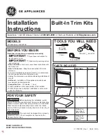
Installation

Built-In Trim Kits

Instructions

JX1527  JX1530

1

❒ 

BEFORE YOU BEGIN

Read these instructions completely and carefully.

IMPORTANT 

Save these instructions 

for local inspector’s use.

IMPORTANT 

Observe all governing codes 

and ordinances.

• Note to Installer – 

Be sure to leave these instructions 

with the Consumer.

• Note to Consumer – 

Keep these instructions for future

reference.

• Skill level – 

Installation of this appliance requires basic

mechanical and electrical skills.

• Completion time – 

1 to 3 hours

Proper installation is the responsibility of the installer. 

Product failure due to improper installation is not covered
under the Warranty.

This kit is UL/CSA listed for installation alone or over any
GE/GE Profile single electric wall oven. Not for use adjacent 
to (within 2 feet of) any gas or electric range, cooktop 
or oven.

For easier installation and personal safety, we
recommend that two people install this microwave oven.

Unplug the microwave oven before attempting installation
of this kit.

This kit is for use on models: PEB1590DMBB,
PEB1590DMWW, PEB1590SMSS, PEB159CDNBB,
PEB159CSNSS and PEB159CDNWW. 

Do not alter or modify any part of this kit or the oven.

WARNING 

This oven must be plugged into a

properly grounded 3-hole, 120V receptacle as required by
the National Electrical Code or Canadian Electrical Code.

FOR YOUR SAFETY:

WARNING 

Before beginning the installation,

switch power off at service panel and lock the service
disconnecting means to prevent power from being switched
on accidentally. When the service disconnecting means
cannot be locked, securely fasten a prominent warning
device, such as a tag, to the service panel.

Questions? In the U.S., call 800.GE.CARES (800.432.2737) 

or Visit our Website at:

ge.com.

In Canada, call 1.800.561.3344 

or Visit our Website at:

GEAppliances.ca.

Summary of Contents for JX1527

Page 1: ...e to improper installation is not covered under the Warranty This kit is UL CSA listed for installation alone or over any GE GE Profile single electric wall oven Not for use adjacent to within 2 feet of any gas or electric range cooktop or oven For easier installation and personal safety we recommend that two people install this microwave oven Unplug the microwave oven before attempting installati...

Page 2: ...2x4 or 1x2 equivalent runners on all sides Base must be capable of supporting a minimum of 100 lbs 45 3 kg 1 Min depth with 120V 60 Hertz grounded power receptacle outside cabinet 211 2 Min depth with 120V 60 Hertz grounded power receptacle inside cabinet 23 Models 27 30 Height 183 4 183 4 Width 24 1 16 24 1 16 Depth min 211 2 or 23 211 2 or 23 INSTALL THE ANTI TIP BRACE Draw a line on the cutout ...

Page 3: ...hesive backing from the upper duct and secure it to the microwave oven by pressing it firmly down on duct Fasten the upper duct with the two screws just removed from the microwave oven Place the top bracket on top of the upper duct with the opening on the top bracket lined up with the opening on the duct Attach the top bracket to the upper duct using two round head screws B A 4 Microwave oven upsi...

Page 4: ...t openings at the bottom Press the trim frame into the opening until all sides snap into place Open the microwave oven door Secure the trim frame using four flat head screws two on the inside top and two on the inside bottom C B A 8 REPLACE ANY LOOSE ITEMS Your trim kit is now fully installed Replace the turntable and turntable support that were removed from the inside of the microwave oven Keep t...

Page 5: ...auvaise installation n est pas couverte par la garantie Cet ensemble est homologué CSA UL pour une installation seule ou combinée avec un four encastré électrique simple GE ou GE Profile Ce four à micro ondes ne peut être installé à moins de 2 pieds d une cuisinière au gaz ou électrique d une surface de cuisson ou d un four Pour une installation plus facile et votre propre sécurité nous recommando...

Page 6: ...minimale de 100 lb 45 3 kg Profondeur min avec prise mise à la terre de 120 V et 60 Hz à l extérieur de l ouverture 211 2 po Profondeur min avec prise mise à la terre de 120 V et 60 Hz à l intérieur de l ouverture 23 po Modèles 27 po 30 po Hauteur 183 4 po 183 4 po Largeur 24 1 16 po 24 1 16 po Profondeur min 211 2 ou 23 po 211 2 ou 23 po MONTAGE DU RENFORT DU SUPPORT ANTIBASCULEMENT Tracez une li...

Page 7: ...four à micro ondes Retirez l une des vis de la caisse du four à micro ondes Placez le conduit inférieur sur la partie inférieure du four à micro ondes et fixez le au moyen de six vis à tête ronde et de la vis retirée précédemment du four à micro ondes Retournez le four en orientant le côté droit vers le haut et en vous assurant que le rebord du conduit inférieur ne fléchit pas Support antibasculem...

Page 8: ... ouverture jusqu à ce que tous les côtés s enclenchent en position Ouvrez la porte du four à micro ondes Fixez le cadre de finition avec quatre vis à tête plate deux à l intérieur et au haut et deux à l intérieur et au bas REMISE EN PLACE DE TOUTES LES PIÈCES MOBILES Votre cadre de finition est maintenant installé Remettez le plateau tournant et le support du plateau tournant à l intérieur du four...

Reviews: