GEH-3851C
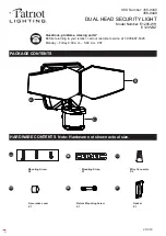
HLU, VLU Powerflood
®
Floodlight
INSTRUCTIONS
GENERAL
This luminaire is designed for outdoor lighting applica-
tions, and should not be used in areas of limited
ventilation or in high ambient temperature enclosures. Best
results will be obtained if installed and maintained
according to the following recommendations.
UNPACKING
This luminaire has been properly packed so that no
parts should have been damaged during transit. Inspect to
confirm.
MOUNTING
TRUNNION MOUNTED UNITS
— Mounted directly on a
flat surface. Mounting adapters are available for installa-
tion on poles, crossarms, pipes, etc. The trunnion bracket
has a clearance hole for a 3/4-inch bolt used for attach-
ment to such mountings. The 0.562-inch holes on either
side permit additional anchoring, where required. Tighten
side trunnion bolts to 18 - 22 foot pounds.
PIPE MOUNTED UNITS
— The slipfitter can be
mounted on 1-7/8-inch O.D. through 2-3/8-inch O.D. or
2-7/8-inch O.D. through 3-inch O.D. pipes. Three set
screws are used to clamp the floodlight securely to the pipe.
Tighten set screws to 18 - 22 foot pounds.
WALL MOUNTED UNITS
- The wall mounting plate is
provided with four (4) 0.438-inch clearance holes spaced
4.375(H)x2.875(V) inches for mounting.
AIMING
Slightly loosen bolt "A" (two on trunnion, one on
slipfitter), tilt luminaire to desired position, and retighten
bolts. Both trunnions and slipfitters have vertical degree
scales which permit setting the floodlight at a selected
angle and facilitate repositioning to the original setting
after having moved the floodlight for servicing. Also, a
sight has been cast into the top of the housing as an aid in
aiming the unit during daylight hours.
PHOTOELECTRIC CONTROL
Photoelectric control receptacle (if present) should be
oriented before control is installed. Loosen the two
holding screws and rotate receptacle until "North" is
directed as near as possible to true north. Tighten
holding screws and install control.
WIRING
Make all electrical connections in accordance with
the National Electrical Code and any applicable
local code requirements.
Verify that supply voltage is correct by comparing
it to nameplate.
If unit is designated as multivolt or multiwatt,
follow specific instruction.
Connect ground lead to the green lead, green
ground screw on housing or terminal block
provided.
Do not remove insulated connectors from wires
not needed for required voltage connection.
When changing voltage on reconnectable units,
move only the lead with the insulated connector.
IF SINGLE VOLTAGE:
All single voltage ballasts are pre-wired such that
user need only connect the supply conductors.
IF MULTIVOLT: (120/208/240/277 volts)
Connect the ballast lead with the insulated termi-
nal to the desired voltage terminal as indicated on
the ballast terminal nameplate.
IF MULTIWATT:
Multiwatt ballasts are available in various combi-
nations of wattage. See wiring instructions on
wiring tag inside the luminaire.
TRUNNION MOUNTED LUMINAIRES
— Three-
conductor No. 14 cable (with 90°C minimum insulation)
is recommended for making electrical connections to
these units. Open the floodlight by loosening two screws
"B" and pulling the door forward. Remove the insulation
shield from the reflector to expose the wiring entrance
and terminal board. Loosen screws in pressure plate,
insert cable through grommet, and retighten screws.
(Notice that grommet fits cable of approximately 9/16-
inch diameter.) Grommet and pressure plate form a
weatherproof seal and strain relief. To maintain this
seal, screws in pressure plate must be retightened
whenever seal is disturbed.
Connect line lead to first (#1) terminal board position
and neutral lead to last (#3) position and connect
ground lead to the terminal with the green lead attached.
Before closing luminaire, be sure insulation shield is
properly attached to the reflector.
SLIPFITTER-MOUNTED AND WALL-MOUNTED UNITS
—
Splice supply leads to three leads inside wiring box.
Splice line lead to black lead, neutral lead to white lead,
and ground lead to green lead, which is electrically
connected to floodlight housing.
L A M P S
Use only lamps specified on nameplate. Observe
lamp manufacturer’s recommendations and
restrictions on lamp operation, particularly ballast
type, burning position, etc.
The VLU is designed for high pressure soduim (HPS),
"Deluxe White" mercury, and metal halide lamps of 400
watts and less, depending upon the ballast installed. The
HLU is designed for HPS lamps only.
Lamp Tightness – Mogul Base Lamp:
The lamp
should be securely inserted to the NEMA-EEI specified
torque of 35 inch-pounds, which is best achieved by
very firmly tightening to insure application of sufficient
torque. Tightening must be sufficient to fully depress
and load the center contact of the socket.
MAINTENANCE
35-201578-65 (1/00)
READ THOROUGHLY BEFORE INSTALLING
CAUTION
Unit will fall if not installed properly
•
Follow installation instructions
WARNING
Risk of electric shock
•
Turn power off before servicing
–
see instructions
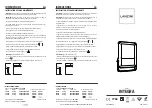
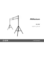
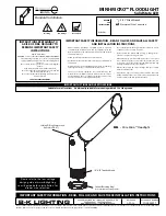
This floodlight is provided with either trunnion mount-
ing, pipe mounting, or wall mounting means.
CAUTION
Risk of burn
•
Allow lamp/fixture to cool before
handling
This unit has a ballast tray which can be removed
for easy replacement of the ballast, ignitor or capacitor.
To remove the tray, disconnect the supply leads from
the terminal board, separate the disconnect to the
lamp and photoelectric control, loosen the screws at
the top of the ballast tray and slide the tray to the
left so that the tray can be pulled free over the
keyhole slots. Reverse this procedure for installation.
The ALGLAS
®
finished reflector and door glass may
be cleaned with any suitable non-abrasive glass cleaning
solution, soap or detergent, and rinsed with clean water.
WARNING
Risk of burn
•
Do not touch operating luminaire
Trunnion Mounted
(Standard)
Slipfitter Mounted
(
Options
K
or
S
)
Wall Mounted
(
Option
V
)
SCREW B
BOLT A
BOLT A
HLUF
VLUF
These instructions do not purport to cover all details or variations in equipment nor to provide for every possible contingency to be met in connection with installation, operation or
maintenance. Should further information be desired or should particular problems arise which are not covered sufficiently for the purchaser’s purposes, the matter should be referred
to GE Lighting Solutions.
g
GE Lighting Solutions is a subsidiary of the General Electric Company. Evolve and other trademarks belong to GE Lighting Solutions. The GE brand and logo are trademarks of the General Electric Company.
© 2011 GE Lighting Solutions. Information provided is subject to change without notice. All values are design or typical values when measured under laboratory conditions.
GE Lighting Solutions • 1-888-MY-GE-LED • www.gelightingsolutions.com
1
6 9 4 3 5 3 3
-
-
-
- 8 8 8
g
GE
Lighting Solutions
Summary of Contents for HLU Powerflood
Page 2: ......