background image

GE Multilin

215 Anderson Avenue

L6E 1B3 Markham, ON -CANADA

Tel: (905) 294 6222   Fax: (905) 294 8512
E-mail: [email protected]

Internet: www.GEMultilin.com

Copyright © 2005 GE Multilin
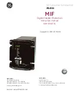
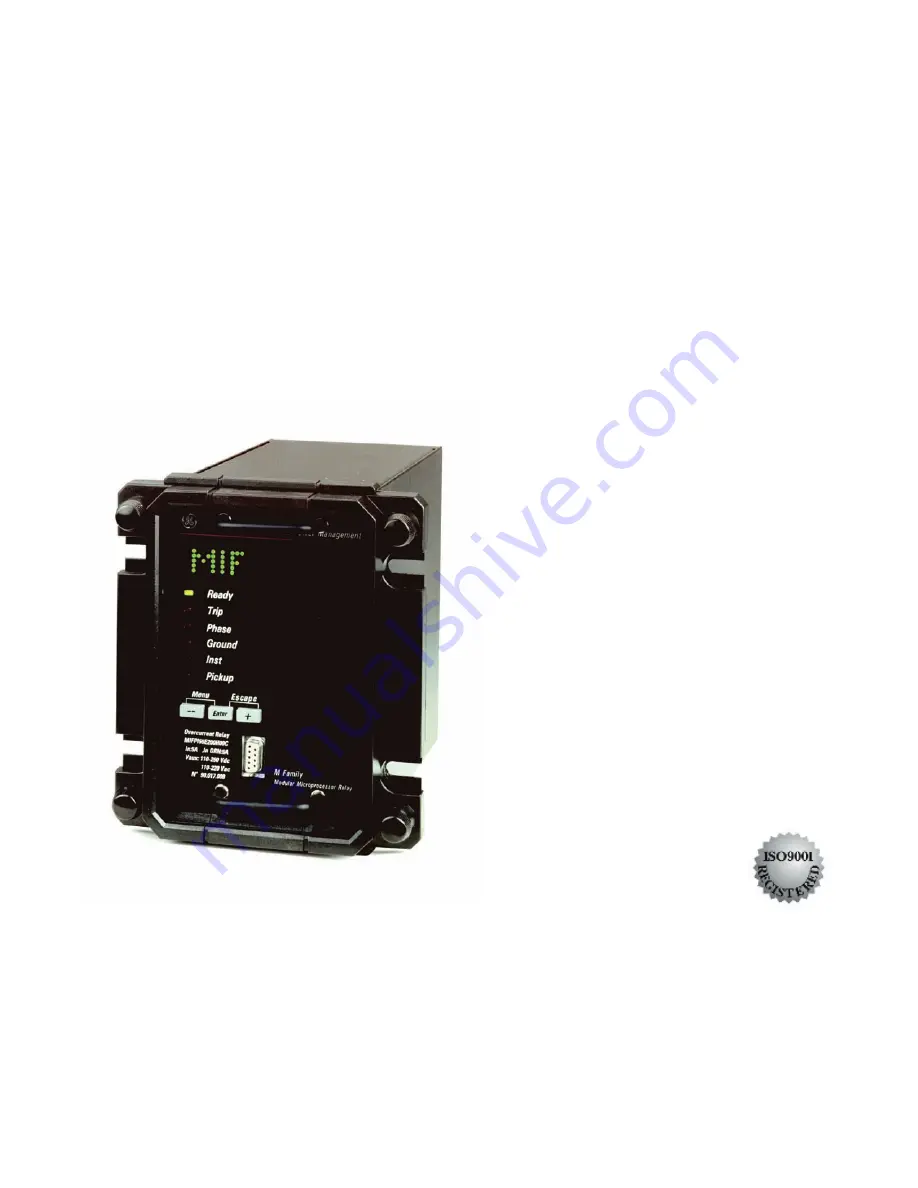
MIF

Digital Feeder Protection

Instruction manual

GEK-106273L

GE Multilin

Avda. Pinoa, 10

48170 Zamudio SPAIN

Tel: +34 94 485 88 00   Fax: +34 94 485 88 45
E-mail: [email protected]

g

GE Consumer & Industrial

Multilin

Summary of Contents for GEK-106273L

Page 1: ...2 E mail gemultilin ge com Internet www GEMultilin com Copyright 2005 GE Multilin MIF Digital Feeder Protection Instruction manual GEK 106273L GE Multilin Avda Pinoa 10 48170 Zamudio SPAIN Tel 34 94 485 88 00 Fax 34 94 485 88 45 E mail gemultilin euro ge com g GE Consumer Industrial Multilin ...

Page 2: ...TIME OVERCURRENT UNIT 51N 2 7 2 2 4 GROUND INSTANTANEOUS OVERCURRENT UNITS 50NH 50NL 2 7 2 3 THERMAL IMAGE UNIT 2 8 2 4 COLD LOAD PICKUP ONLY OPTION 2 MODELS 2 8 2 5 BREAKER FAILURE TO OPEN ONLY OPTION 2 MODELS 2 9 2 6 I2 COUNTER ONLY OPTION 2 MODELS 2 9 2 7 EVENTS AVAILABLE IN OPTION 1 AND OPTION 2 MODELS 2 10 2 8 OSCILLOGRAPHY AVAILABLE IN OPTION 1 AND OPTION 2 MODELS 2 11 2 9 MULTIPLE SETTINGS ...

Page 3: ...3 2 7 RS232 FACEPLATE COMMUNICATIONS PORT 3 36 3 2 8 RS485 COMMUNICATIONS PORT 3 38 4 COMMUNICATIONS 4 1 4 1 ENERVISTA MII SETUP SOFTWARE 4 1 4 1 1 OVERVIEW 4 1 4 1 2 STARTING COMMUNICATION 4 2 4 1 3 MAIN SCREEN 4 2 4 2 FILE 4 3 4 3 SETPOINT 4 6 4 3 1 SETTINGS 4 6 4 3 2 MAIN SETTINGS 4 8 4 3 3 ADVANCED SETTINGS 4 8 4 3 4 RELAY CONFIGURATION 4 9 4 3 5 LOGIC CONFIGURATION 4 11 4 3 6 CLOCK 4 12 4 4 A...

Page 4: ... 5 36 5 3 9 BREAKER FAILURE TO OPEN 5 37 5 3 10 COLD LOAD PICKUP 5 37 5 4 TIME SYNCHRONIZATION 5 37 6 I 0 CONFIGURATION 6 39 6 1 INPUT CONFIGURATION ONLY FOR OPTION 1 AND OPTION 2 MODELS 6 39 6 1 1 DESCRIPTION OF INPUTS 6 39 6 1 2 INPUT FUNCTIONS 6 40 6 2 OUTPUTS AND LEDS CONFIGURATION ONLY FOR OPTION 1 AND OPTION 2 MODELS 6 41 6 2 1 DESCRIPTION OF OUTPUTS AND LEDS 6 41 6 2 2 OUTPUTS AND LEDS FUNC...

Page 5: ...UNIT 50NH 9 6 9 15 GROUND IOC LOW SETTING UNIT 50NL 9 6 9 16 PHASE TOC UNIT 51P 9 6 9 16 1 IEC INVERSE CURVE 9 6 9 16 2 IEC VERY INVERSE CURVE 9 7 9 16 3 IEC EXTREMELY INVERSE CURVE 9 7 9 16 4 ANSI INVERSE CURVE 9 7 9 16 5 ANSI VERY INVERSE CURVE 9 7 9 16 6 ANSI EXTREMELY INVERSE CURVE 9 8 9 17 DEFINITE TIME 9 9 9 18 GROUND TOC UNIT 51N 9 9 9 18 1 IEC INVERSE CURVE 9 9 9 18 2 IEC VERY INVERSE CURV...

Page 6: ...FOR 51P AND 51N UNITS 12 1 13 ANNEX 3 MODBUS MEMORY MAP 13 1 13 1 READING VALUES 13 1 13 2 COMMAND EXECUTION 13 2 13 3 SYNCHRONIZATION 13 4 13 4 WRITING SETTINGS 13 5 13 5 ERRORS 13 7 13 6 MODBUS MEMORY MAP 13 8 13 6 1 STATES 13 8 13 6 2 SETTINGS 13 10 13 6 3 SPECIAL FORMATS 13 12 14 ANNEX 4 MODEM CONNECTION 14 1 14 1 HAYES MODEM 14 1 14 2 V 25BIS MODEM 14 2 14 3 SAMPLES OF SETTINGS FOR PARTICULAR...

Page 7: ...K 106273L 16 ANNEX 6 STATUS LIST 16 1 17 APPLICATION NOTES 17 1 17 1 MIF WITH 1 SHOT RECLOSER 17 1 17 1 1 I O CONFIGURATION 17 2 17 1 2 LOGIC CONFIGURATION 17 2 17 2 TRIP CIRCUIT SUPERVISION FOR M FAMILY RELAYS 17 4 17 2 1 SETTINGS AND CONFIGURATION 17 5 ...

Page 8: ...ical damage View the faceplate relay model number and verify that the relay is the correct model ordered Ensure that the mounting screws have been included with the relay For product information instruction manual updates and the latest software updates please visit the GE Power Management Home Page www geindustrial com pm Note If there is any physical damage noticed on the relay or any of the con...

Page 9: ... the described equipment nor does it take into account the circumstances that may be present in your installation operating or maintenance activities Should you wish to receive additional information or for any particular problem that cannot be solved by referring to the information contained herein please contact GENERAL ELECTRIC POWER MANAGEMENT ...

Page 10: ...stem drive and 40 MB of available space on installation drive RS232C serial and Ethernet port for communications to the relay 1 2 2 INSTALLATION After ensuring the minimum requirements for using EnerVista MII Setup are met see previous section use the following procedure to install the EnerVista MII Setup from the enclosed GE EnerVista CD 1 Insert the GE EnerVista CD into your CD ROM drive 2 Click...

Page 11: ...oftware items for the MIFII FIGURE 1 2 6 If Web option is selected chose the MIFII software program from the list and click the Download Now button to obtain the installation program 7 When EnerVista detects that there is already a version of the program in the Software Library the user will choose whether to install it directly or to check for more versions ...

Page 12: ...for Updated Versions button the program will proceed to search for the different versions of set up program from the Web FIGURE 1 4 9 EnerVista Launchpad will obtain the installation program from the Web If the version the user already has is the last one on the Web the following screen will appear ...

Page 13: ...the ENERVISTA MII SETUP software 12 Select the complete path including the new directory name where the ENERVISTA MII SETUP will be installed 13 Click on Next to begin the installation The files will be installed in the directory indicated and the installation program will automatically create icons and add ENERVISTA MII SETUP to the Windows start menu 14 Follow the on screen instructions to insta...

Page 14: ...ory click Change and type in the complete path name including the new directory name and click Next to continue with the installation procedure FIGURE 1 7 16 The default program group where the application will be added to is shown in the Selected Program Folder window Click Next to begin the installation process and all the necessary program files will be copied into the chosen directory ...

Page 15: ...GETTING STARTED 1 8 MIF Digital Feeder Protection GEK 106273L FIGURE 1 8 17 To finish with the installation process select the desired language for startup FIGURE 1 9 ...

Page 16: ...ARTED GEK 106273L MIF Digital Feeder Protection 1 9 18 Click Finish to end the installation The MII device will be added to the list of installed IEDs in the EnerVista Launchpad window as shown below FIGURE 1 10 ...

Page 17: ...onverter box is connected to the computer using a straight through serial cable A shielded twisted pair 20 22 or 24 AWG according to the American standards 0 25 0 34 or 0 5 mm2 according to the European standards cable is used to connect the converter box to the relay rear communications terminals The converter box GND terminals are connected to the relay SDA SDB GND terminals respectively For lon...

Page 18: ...ation within the same hierarchical level horizontal movement push or To access the third level push the Enter key when the desired heading is shown in the display To return back to the previous level from the third to the second level or from the second to the first one push and Enter keys simultaneously This is indicated by the Esc text labelled over the and Enter keys Refer to Chapter 8 Keypad a...

Page 19: ...GETTING STARTED 1 12 MIF Digital Feeder Protection GEK 106273L ...

Page 20: ...t a time delay for the instantaneous units allow optimal co ordination without compromising selectivity Both faceplate RS232 port and rear RS485 port may be used to connect a PC for programming settings monitoring actual values and for retrieving stored information list of events oscillography etc All serial ports use the Modbus RTU protocol and may be connected to system computers with baud rates...

Page 21: ...PRODUCT DESCRIPTION 2 2 MIF Digital Feeder Protection GEK 106273L Figure 2 1 SINGLE LINE DIAGRAM SHOWING MIF FUNCTIONS ...

Page 22: ...e dial can be applied to any of these curves to optimize co ordination with other devices in the net Additionally there is a possibility to define a User s Curve which can be used for both three phase overcurrent and ground units 2 2 1 1 IEC CURVES Response times for IEC curves are as follows Where CURVE NAME A P Q B K Inverse IEC Curve C 0 14 0 02 1 0 0 Very Inverse IEC Curve B 13 5 1 1 0 0 Extre...

Page 23: ... 7222 Very Inverse 0 0615 0 7989 0 3400 0 2840 4 0505 Inverse 0 0274 2 2614 0 3000 4 1899 9 1272 M Time Dial setting set in the relay by user V I Ipickup setting 1 05 3 2 C V E C V D C V B A M T be will time tripping 20 00 V 1 05 For trip a not but signal pickup a produce will unit the 1 05 V 1 For setting the times 20 00 for as same the be will time tripping the V 20 00 For 3 2 20 20 20 C E C D C...

Page 24: ...tting I Input current Ipkp Pickup Current Setting A to E Constants Table 2 1 GE TYPE IAC INVERSE TIME CURVE CONSTANTS IAC Curve Shape HMI A B C D E IAC Extremely Inverse Extr Inverse 0 0040 0 6379 0 6200 1 7872 0 2461 IAC Very Inverse Very Inverse 0 0900 0 7955 0 1000 1 2885 7 9586 IAC Inverse Mod Inverse 0 2078 0 8630 0 8000 0 4180 0 1947 IAC Inverse Long Inverse Long 0 3754 17 8307 0 32 23 7187 ...

Page 25: ...ned in the standard as follows The settings available for the phase time overcurrent unit allows to enable disable the unit set the pickup value between 0 1 2 4 times the rated current in case of 1 5 A ground or 0 005 0 12 A in case of sensitive ground and set the current time operating characteristic type and time dial Note The relay will use either IEC or ANSI curves depending on the model K D B...

Page 26: ...D TIME OVERCURRENT UNIT 51N The Ground Time Overcurrent unit offers the same setting possibilities as the Phase Time Overcurrent unit The ground current can be obtained from a residual connection on the CTs For a more sensitive ground current detection a window type zero sequence CT taking the three phases inside its windows can be used Refer to figure 3 6 for more details 2 2 4 GROUND INSTANTANEO...

Page 27: ...it returns to its original status When the timer countdown has finished the tap settings of the instantaneous phase units 50PH and 50PL is multiplied by a constant K50P and the phase TOC 51P tap settings are multiplied by a constant K51P A status signal turns on indicating that the Cold Load Pickup is enabled and the corresponding event is generated For exiting the CLP status when the current valu...

Page 28: ...ermission and the timer value They are included in the ADVANCED SETTINGS group They will be described in the SETTINGS section 2 6 I2 COUNTER ONLY OPTION 2 MODELS This counter is intended for breaker maintenance It accumulates the breaker ageing produced by a trip or a breaker opening In order to incorporate the breaker history in case of second hand breakers the system allows assigning an initial ...

Page 29: ... there is a sub group called EVENT MASKS from where the different causes that can produce events can be masked They are detailed in the SETTINGS section The following table shows a list of all possible events DESCRIPTION OPTION 1 OPTION 2 50PH Pickup Drop out Yes Yes 50PL Pickup Drop out Yes Yes 50NH Pickup Drop out Yes Yes 50NL Pickup Drop out Yes Yes 51P Pickup Drop out Yes Yes 51N Pickup Drop o...

Page 30: ...ings change Yes Yes E2PROM failure Yes Yes User settings Factory settings Yes Yes OPTION 1 MIFP E100 00 OPTION 2 MIFP E200 00 2 8 OSCILLOGRAPHY AVAILABLE IN OPTION 1 AND OPTION 2 MODELS The MIF stores an oscillography record with a resolution of 8 samples per cycle and a length of 24 cycles the 2 first being pre fault cycles including the following information Instantaneous values of phase Ia Ib I...

Page 31: ...tioned causes can be masked They are detailed in the SETTINGS section Protection functions 50PH 50PL 50NH 50NL 51P 51N 49 general 2 9 MULTIPLE SETTINGS GROUPS Two independent Settings Groups are available in the permanent non volatile memory of the MIF relay Only one of the two is active at a given time User can select which settings group is active using a setting sending a command to the relay f...

Page 32: ...one of the Phase Overcurrent Units GROUND Points out that the trip has been issued by one of the Ground Overcurrent Units INST Points out that the trip has been issued by one of the Instantaneous Units either phase or ground units PICKUP Points out that at least one of the protective units has picked up LEDs associated to tripping functions are latched and once they have been lit up they remain li...

Page 33: ...0 bps Up to 32 MIF relays can be connected daisy chained on the same communication circuit Each relay must be assigned a different Modbus Address using a setting if multiple relays are connected on the same circuit Software MIF units are supply together with ENERVISTA MII SETUP software a Windows based software allowing communication with the relay for data view and retrieval as well as oscillogra...

Page 34: ... case can hold a maximum of 16 in total module length i e 4 MIFs 2 MIF and 4 MIVs or 8 MIV modules A system comprised of several M family relays in the same case is called an M System The information required to completely specify the relay is provided in the following table Table 2 2 ORDER CODES MIF 0 0 DESCRIPTION P 3 Phase Ground A ANSI Curves I IEC Curves Phases 1 CT In 1A 0 1 2 4 A 5 CT In 5A...

Page 35: ...are to be mounted in an M system then either an M050 half 19 rack or M100 full 19 must be ordered The M050 and M100 racks are provided at no additional cost ACCESSORIES A depth reducing collar can be ordered separately This collar reduces the mounting depth in 63 mm 2 48 inches ...

Page 36: ...ed 0 00 to 600 00 sec in steps of 0 01 sec 0 05 to 2 in steps of 0 01 for IEC curves 0 5 to 20 in steps of 0 1 for ANSI curves Instantaneous 5 of operate time or 30 ms whichever is greater for I 1 50 times the Actual Pickup Level PHASE GROUND INSTANTANEOUS OVERCURRENT 50PH 50PL 50NH 50NL Current Pickup Level Dropout Level Level Accuracy Overreach Time Delay Reset Type Operate Time Timing Accuracy ...

Page 37: ...1 in steps of 1 From 70 to 100 Ipickup in steps of 1 5 for operate times greater than 2 sec 2 13 2 METERING FUNCTIONS FUNDAMENTAL CURRENT Accuracy 1 at In 3 in the complete range 2 13 3 INPUTS AC CURRENT Secondary Rated Current Frequency Relay Burden Current Withstand 1m 5 A depending on the selected model or 50 mA for sensitive ground models 50 60 Hz 3 Hz The unit can be set to 50 or 60 Hz 0 2 VA...

Page 38: ...0 to 230 Vac 50 60 Hz 88 264 Vac 50 60 Hz Power Consumption Max 10 W Proper backup time date time and log memory without power supply voltage 1 week 2 13 5 OUTPUTS OUTPUT RELAYS Configuration 6 Electro Mechanical Form C Contact Material Silver alloy suited for inductive loads Maximum Operating Voltage 400 Vac Continuous Mode Current 16 A at 250 Vac general purpose HP 124 Vac 1 1 2 HP 250 Vac 10 A ...

Page 39: ...125 Vdc 16 A 48 A 0 3 A 37 5 W 250 Vdc 16 A 48 A 0 25 A 62 5 W AC Resistive 120 Vac 16 A 48 A 16 A 1920 VA 250 Vac 16 A 48 A 16 A 4000 VA AC Inductive PF 0 4 120 Vac 16 A 48 A 16 A 720 VA 250 Vac 16 A 48 A 16 A 1250 VA 2 13 6 COMMUNICATIONS FACEPLATE PORT RS232 300 600 1200 2400 4800 9600 or 19200 bps Modbus RTU REAR PORT RS485 300 600 1200 2400 4800 9600 or 19200 bps Modbus RTU 2 13 7 ENVIRONMENT...

Page 40: ... 1 MHz Interference IEC 60255 22 1 III Electrostatic Discharge IEC 60255 22 2 EN 61000 4 2 IV 8 kV in contact 15 kV through air Radiointerference IEC 60255 22 3 40 MHz 151 MHz 450 MHz and cellular phone III Radiated Electromagnetic fields with amplitude modulation ENV 50140 10 V m Radiated Electromagnetic fields with amplitude modulation Common mode ENV 50141 10 V m Radiated Electromagnetic fields...

Page 41: ...PRODUCT DESCRIPTION 2 22 MIF Digital Feeder Protection GEK 106273L 2 13 10 APPROVALS Manufactured under an ISO9001Registered system CE Marking UL Certified ...

Page 42: ...ensions along with panel cutout details for panel mounting are shown in figure 3 2 The modular design allows the relay to be easily upgraded or repaired by a qualified person The relay is provided with a plastic lid that fits over the faceplate sealing the relay hermetically avoiding dust coming into the relay The relay must be mounted such that the faceplate sits semi flush with the panel or swit...

Page 43: ...DESCRIPTION 3 24 MIF Digital Feeder Protection GEK 106273L Note Dimensions are shown in mm and in inches between parenthesis Figure 3 2A MOUNTING AND DIMENSIONS DRAWING FOR MIF MODELS WITH DEPTH REDUCING COLLAR ...

Page 44: ...module firmly in the case using the knobs until it is completely inserted Once this is done bolt the screws of the faceplate and replace the control power Check if the relay is fully operative Finally replace the methacrylate cover 3 1 4 WIRING AND INTERNAL CONNECTIONS The electrical connection with the substation AC DC wires is done on the three terminal blocks at the rear part of the relay case ...

Page 45: ...and have been assigned the letters A B and C respectively in order to avoid confusions while wiring external cables For each terminal block the wiring screws 1 to 12 have been labelled with their corresponding number Figure 3 4 shows the location and identification of the terminals blocks at the rear of the MIF relay Recommended cable section 12 16 AWG Cable material copper Tightening torque 1 2 N...

Page 46: ...N GEK 106273L MIF Digital Feeder Protection 3 27 3 2 WIRING 3 2 1 TYPICAL WIRING DIAGRAM Recommended cable section 12 16 AWG Cable material copper Tightening torque 1 2 Nm Figure 3 5 TYPICAL WIRING DIAGRAM FOR MIF RELAY ...

Page 47: ...ON CONTROL POWER SUPPLIED TO THE RELAY MUST MATCH THE RATED VOLTAGE OF THE RELAY IF THE VOLTAGE IS APPLIED TO THE WRONG TERMINALS DAMAGE MAY OCCUR Table 3 1 Control Power Voltage Range RANGE RATED VOLTAGE OPERATION RANGE F 24 48 Vdc 19 2 57 6 Vdc H 110 250 Vdc 110 230 Vac 88 300 Vdc 88 264 Vac ...

Page 48: ...rrent may be used CAUTION VERIFY THAT YOUR RELAY MODEL CORRESPONDS TO YOUR RATED SECONDARY CURRENT UNMATCHED CTS MAY RESULT IN EQUIPMENT CMAGE OR INADEQUETE PROTECTION The exact placement of a zero sequence CT so that ground fault current will be detected is shown below Twisted pair cabling on the zero sequence CT is recommended Figure 3 6 ZERO SEQUENCE CORE BALANCE CT INSTALLATION UNSHIELDED CABL...

Page 49: ...ge range relays F model the threshold is set to 12 Vdc For high voltage range relays H model the voltage threshold is 75 Vdc In case of using AC voltage it must be ensured that there is no appreciable voltage less than 10 Vac between the input common terminal A10 and the ground terminal The AC system must be line neutral type and not line line ensuring that the neutral and ground do not differ in ...

Page 50: ...tput relay it is possible to select which state is preferred to have at the MIFII terminals NC normally closed or NO normally open The figure shows the PCB of a MIFII relay and the location of the jumpers used to select the configuration of each output contact NO or NC FIGURE 3 8 PCB SCHEME SHOWING THE JUMPERS TO CONFIGURE THE OUTPUT CONTACTS NC NO CRITICAL OUTPUT 1 OUTPUT 2 OUTPUT 3 OUTPUT 4 C O ...

Page 51: ...er of outputs is reduced to three Jx jumper is closed in the factory default configuration It is possible to order relays with Jx removed The figure shows the factory default configuration with Jx Jumper closed It is located on the soldering part of the PCB containing the inputs and outputs FIGURE 3 9 JX JUMPER The Jx jumper is a tin solder jumper easy to remove using a de soldering tool The stand...

Page 52: ...rm Each output has a different configuration and it is able to operate independently to the others If Jx jumper is removed the output contact configuration change as shown in the following figure After removing the Jx Jumper the outputs are divided in two groups Independent and isolated Group1 Output 1 Terminals B8 B7 Group 2 Output 2 Terminals B9 A7 Output 3 Terminals B10 A7 ...

Page 53: ... B8 one of the two following procedures should be followed Jx Removed and OUT1 and OUT2 normally open OUT1 and OUT2 must operate together to operate like a single output The configuration of OUT1 and OUT2 must be the same so both outputs close simultaneously and operate successfully Jx Removed and one of the two internal contacts set as normally closed ...

Page 54: ...ry to configure by software the OUT1 as NOT ASIGNED so it never change its state and remains closed and OUT2 as required by the application output configuration is only available in models option 1 and 2 o OUT1 normally open and OUT2 normally closed The hardware configuration corresponds to OUT1 NO and OUT2 NC To operate with this hardware configuration it is necessary to configure by software the...

Page 55: ...pin RS232C serial port is located on the relay s faceplate for programming with a portable personal computer All that is required to use this interface is a personal computer running the ENERVISTA MII SETUP software Figure 3 9 shows the communications cable configuration Figure 3 9 RS232 FACEPLATE PORT CONNECTION ...

Page 56: ...rrectly grounded either due to the power supply itself or to the connector cables used This way feeding the portable PC with its internal battery the worst case would be an incorrect communication but we drastically decrease the possibility of producing permanent damage to the computer or the relay Beware of the possibility of losing communication in firmware change processes This is required not ...

Page 57: ...re are exceptions to this rule such as ALPS and DDS family relays The GND terminal should be connected to the common wire inside the shield when provided Otherwise it should be connected to the shield To avoid loop currents the shield should be grounded at one point only Each relay should also be daisy chained to the next one in the link A maximum of 32 relays can be connected in this manner witho...

Page 58: ...ith setting files 1 In off line mode disconnected from the relay creating or editing setting files for a future download to the relay 2 Modifying directly the relay settings while connected to the relay b Configuration The configuration of inputs outputs and LEDs can be modified and internal logics with the different relay elements can be created For MIF it depends on the selected option OPTION 0 ...

Page 59: ...y not be possible or the relay and or the computer could be damaged To work online the relay communication parameters e g baud rate relay address and password must match the parameters in the computer The computer parameters can be modified in the Communication Computer menu Refer to the appropriate section in this same chapter for more details 4 1 3 MAIN SCREEN The main screen of ENERVISTA MII SE...

Page 60: ...el matching exactly the relay model to which the settings and configuration will later be downloaded The mentioned settings and configuration are related to the default factory settings of the relay FIGURE 4 2 Once the relay model is selected the software will load the relay structure and will enable the Setpoint Actual Communication View and Help menus for configuration OPEN Option that allows to...

Page 61: ...ables the user to save the relay settings in a file on the hard disk of the computer This file can later be opened offline to review and modify settings and send them again to the relay after the modifications SEND INFO TO RELAY The File Get info from relay option enables to send to the relay a settings file stored on the hard disk of the computer PRINT SETUP The File Print Setup option enables th...

Page 62: ...ible to configure the printer that will be used or to directly print the document Double clicking on the document with the left mouse button will enlarge the document view and double clicking with the right button will reduce the size The available actions in this screen are shown in figure 4 5 FIGURE 4 5 PRINT PREVIEW CONTROLS PRINT The File Print option prints the relay settings using Windows de...

Page 63: ...s division is to simplify the use of the relay for those users only requiring the basic functionality of the relay FIGURE 4 6 SETTINGS MENU Once in the corresponding sub menu either Main Settings or Advanced Settings the procedure to enter and modify any setting value is the same Select the settings group the function selected in the example is the 51P Function in a MIF II Edit the setting double ...

Page 64: ... with the mouse on the option desired Numerical Settings For Numerical settings a number must be entered The program shows the minimum and maximum value for each setting and it will not accept any value out of the corresponding range Settings with a set of options For set of options settings a pop up window is shown containing all possible values Select the appropriate one clicking on it Text Sett...

Page 65: ...Group 1 is available in the Main Settings group while Group 2 can be accessed in the Advanced Settings group The setting groups can be selected by digital input through a communications command or from the ENERVISTA MII SETUP or simply selecting it with the relay keypad The setting that shows the active group can be found in General Advanced Settings 4 3 3 ADVANCED SETTINGS 4 3 3 1 ADVANCED GENERA...

Page 66: ...rent columns is explained below INPUT LED OUTPUT Designates the respective element I O configuration the appearance and function of this column can be depending on the state of the respective OR checkbox column OR checkbox is not checked the element consists of a drop down list in which the user can select the function that will activate the output or LED or that will be activated by the input OR ...

Page 67: ...tuate when the conditions are NOT fulfilled NAME the user can write an identifying label of up to 4 characters that will get stored to be displayed later on BLINK only for LEDs the selection of BLINK checkbox makes the LED blink alternatively switch ON and OFF instead of being fixed when it is activated MEMORY only for outputs and LEDs when MEMORY checkbox is enabled the respective element will be...

Page 68: ... they are programmed is similar to the way I Os are refer to relay configuration The device will not take into account entries that are after an empty one This means that every entry after the first empty one will be ignored For example if L1 IN1 is programmed but L1 IN2 is left empty the relay will not take into account L1 IN3 and will directly evaluate L1 IN4 In the same way the relay will ignor...

Page 69: ...h two choices Sending the PC date and time to the unit this is synchronizing the PC and the unit Selecting a date and a time and sending it to the relay FIGURE 4 14 CLOCK Once the new date and time have been sent the user can check in the status graph or even in the relay itself that the new date time has been correctly entered ...

Page 70: ...nal information There is a vertical scroll bar to navigate up and down the table to reach the desired information Relay model number and firmware version Relay internal date and time Values of currents voltages and powers phase and ground Protection function status pickup trip for each function Active settings group number Contact inputs and outputs status and LEDs status Information from the self...

Page 71: ...nd a list of the status of all inputs outputs and functions during the event Additionally the program also shows current and voltage values for all phases and ground frequency and single line sequence voltage during the event FIGURE 4 16 EVENTS WINDOW The retrieved events can be reviewed in this window or also saved to disk to be opened with ENERVISTA MII SETUP program or exported to CSV Comma Sep...

Page 72: ...Oscillography record stored in the relay The program will request the path and filename where the file is to be stored by means of the following form FIGURE 4 17 OSCILLOGRAPHY RECORD This file can be viewed using GE_OSC software the use of this software is described in manual GEK 105596 4 5 OPERATIONS From Operations menu the user can perform all possible operation commands ...

Page 73: ...a ModBus communication troubleshooting or to update the relay with a new firmware After making any change pressing Store button saves the changes without exiting the window Pressing OK saves and exits and pressing Cancel exits without saving changes 4 6 1 COMPUTER In COMPUTER dialog the user can configure the necessary adjustments to communicate with the relay from a PC FIGURE 4 18 COMMUNICATIONS ...

Page 74: ...appears at the right to configure the IP address the port number and the unit id FIGURE 4 19 MODBUS TCP SETUP MODEM CONNECTION for modem serial connection The modem configuration options appear at the right when this option is chosen Defaults button returns the values to the factory default ones 4 6 1 2 COMMUNICATION CONTROL In COMMUNICATIONS CONTROL box the user can view the communication status ...

Page 75: ...ppear FIGURE 4 21 COMMUNICATION CONTROL COMMUNICATING 4 6 1 3 COMMUNICATION OPTIMIZATION COMMUNICATIONS OPTIMIZATION box allows the user to enter values to control device response to communication attempts Changing these parameters can improve communication although it is recommended not to make changes to the default values if it is not required FIGURE 4 22 COMMUNICATION OPTIMIZATION 1 i e the fi...

Page 76: ...e window the one with all the communication parameters Yes means capturing the whole screen and No means capturing only the communications window Then a new window appears allowing to view the captured screen to save the captured file in BMP or JPG format or to print it the print dialog window will appear so as the user can select which printer to use and enter the appropriate printer settings FIG...

Page 77: ... of data to read Setpoints Actual Values the number of registers the length of each register is of 2 bytes and the format of the data integer long float checking the checkbox at the left to make the PC start polling that address or unchecking it to stop In the lower part data can be sent to writeable addresses of the relay The working is similar to reading but to send the data the user must press ...

Page 78: ...elay the user must switch communication off in Communication Computer menu to activate this option When this option is selected a window appears asking for the new firmware version file to be uploaded to the relay FIGURE 4 25 FLASH UPDATE FILE After selecting the file that will be used to update the FLASH memory the following screen will be displayed showing details of the old model and the new mo...

Page 79: ...rder Serial number of the unit Current model option before memory update Desired model option after memory update In a case where more than one unit needs to be updated all the serial numbers must be detailed and a different password will be assigned for each unit FIGURE 4 27 PASSWORD If the update does not require changes to the functionality of the relay the program will not request a password A...

Page 80: ... may result a critical issue when the relay is integrated in a system and the user should take into account the modifications that will have to be performed in the programs that access the MIF II relay memory maps Additionally when a Flash memory update is performed the loading program will enter the default settings This means that the user will need to adapt the settings to the real situation of...

Page 81: ... when the PC is communicating with the relay If the communication is not established to activate this option the user must switch communication on in Communication Computer menu When TRACES are active the ModBus communication traces will be displayed in the lower part of the screen as shown in figure 4 30 FIGURE 4 30 MODBUS TRACES ...

Page 82: ...communication on in Communication Computer menu With MODBUS MEMORY MAP option the user can extract the complete memory map from the relay and print or save it in CSV format to be later opened with any database or spreadsheet program as MS Excel It is recommended to use this feature as memory map changes with relay model and firmware version so this is the safest way of obtaining the appropriate me...

Page 83: ...GEK 106273L 4 7 3 LANGUAGES LANGUAGES option is only active when there is no active communication with the relay If the PC is communicating with the relay to activate this option the user must switch communication off in Communication Computer menu FIGURE 4 32 LANGUAGES ...

Page 84: ... used to handle the settings the following steps must be considered 1 Make sure your communication cable matches the scheme shown in figure 3 9 2 Connect the communications cable between the relay or modem and the computer serial port 3 Run the ENERVISTA MII SETUP program The procedure to install and use the ENERVISTA MII SETUP program is described in section 1 2 2 SOFTWARE INSTALLATION and in sec...

Page 85: ...ENERAL SETTINGS GENERAL SETTINGS GENERAL Relay Status RELAY STATUS STA DIS RDY DIS NA Frequency FREQUENCY FRQ 50 Hz 50 60 Hz NA Phase CT ratio PHASE TRANSF RATIO CT PH 1 1 4000 1 Neutral CT ratio NEUTRAL TRANSF RATIO CT N 1 1 4000 1 Password PWD 1 1 255 Address ADD 1 1 255 1 Communications Speed BAUD 9600 300 600 1200 2400 4800 9600 19200 NA ...

Page 86: ...0 05 2 00 IEC curves 0 01 5 0 5 20 0 ANSI curves 0 01 51P Definite Time Delay 51P Definite Time TIME 51P 1 s 0 600 00 s 0 01 s Ground TOC Function 51N Function F51N 51N Permission to Trip 51N Trip Permission TRIP 51N No Y N NA 51N Tap Pickup for 1 5 A ground 51N Pickup TAP 51N 0 5 In Ground 0 1 2 4 In Gnd 0 01 In Gnd 51N Tap Pickup for sensitive ground 51N Pickup TAP 51N 0 005 A 0 005 0 12 A 0 001...

Page 87: ... 1 In Ph 50PL Time Delay 50PL Time Delay TIME 50PL 0 s 0 600 00 s 0 01 s Ground IOC High Set 50NH Function F50NH 50NH Permission to Trip 50NH Trip Permission TRIP 50NH No Y N NA 50NH Tap Pickup for 1 5 A ground 50NH Pickup TAP 50NH 1 In Ground 0 1 30 In Gnd 0 1 In G 50NH Tap Pickup for sensitive ground 50NH Pickup TAP 50NH 0 005 A 0 005 0 12 A 0 001 A 50NH Time Delay 50NH Time Delay TIME 50NH 0 s ...

Page 88: ...L SETTINGS ENERVISTA MII SETUP HMI DEFAULT RANGE STEP General Settings Adv GENERAL SET ADV GENERAL ADVANCED Identification IDENTIFICATION MIF Text NA Active Table ACTIVE TABLE TAB 1 1 2 NA Trip Contact Minimum time closed TRIP MINIMUM TIME TRIP MIN TIME 200 ms 50 300 ms 1 ms NOTE ABOUT THE TRIP MIN TIME SETTING This setting indicates the time during which the tripping contact will remain closed as...

Page 89: ...EC curves 0 01 5 0 5 20 0 ANSI curves 0 01 51P Definite Time Delay 51P Definite Time T2 TIME 51P T2 1 s 0 600 00 s 0 01 s Gnd TOC Fun Table 2 51N Function Table 2 F51N T2 51N Permission to Trip 51N Trip Permission T2 TRIP 51N T2 No Y N NA 51N Tap Pickup Value 1 5 A ground 51N Pickup T2 TAP 51N T2 0 5 In Ground 0 1 2 4 In Gnd 0 01 In G 51N Tap Pickup Value sensitive ground 51N Pickup T2 TAP 51N T2 ...

Page 90: ...In Ph 50PL Time Delay 50PL Time Delay T2 TIME 50PL T2 0 s 0 600 00 s 0 01 s Gnd IOC High Set Table 2 50NH Function Table 2 F50NH T2 50NH Permission to Trip 50NH Trip Permission T2 TRIP 50NH T2 No Y N NA 50NH Tap Pickup 1 5 A ground 50NH Pickup T2 TAP 50NH T2 1 In Ground 0 1 30 In Gnd 0 1 In G 50NH Tap Pickup Value sensitive ground 50NH Pickup T2 TAP 50NH T2 0 005 A 0 005 0 12 A 0 001 A 50NH Time D...

Page 91: ... Y N NA 49 Tap Pickup 49 Pickup T2 TAP 49 T2 1 In Phase 0 1 2 4 In Ph 0 01 In Ph Overload Percent Alarm 49 Alarm Level T2 ALARM 49 T2 80 70 100 ITH Heating Time Constant τ1 T1 T2 T1 T2 6 3 600 min 1 min Cooling Time Constant τ2 T2 T2 T2 T2 1 1 6 times τ1 1 5 3 5 USER S CURVE ENERVISTA MII SETUP HMI DEFAULT RANGE STEP Parameters USU Function A A A 0 05 0 125 0 001 B B B 0 0 3 0 001 P P P 0 04 0 3 0...

Page 92: ... 50PH disabled YES Y N NA 50PL Trip enable disable by digital input 50PL disabled YES Y N NA 50NH Trip enable disable by digital input 50NH disabled YES Y N NA 50NL Trip enable disable by digital input 50NL disabled YES Y N NA 51P Trip enable disable by digital input 51P disabled YES Y N NA 51N Trip enable disable by digital input 51N disabled YES Y N NA General Trip enable disable by digital inpu...

Page 93: ...ettings change Settings change YES Y N NA E2prom failure e2prom failure YES Y N NA User settings Factory settings User settings YES Y N NA 5 3 7 OSCILLOGRAPHY MASKS ENERVISTA MII SETUP DEFAULT RANGE STEP Oscillography masks Oscillography masks Oscillo by communications Oscillo by communic NO Y N NA Oscillo by digital input Oscillo by Digital Input NO Y N NA Oscillo by tripping Oscillo by tripping ...

Page 94: ...E 1 2 The procedure to set the Phase and Ground TOC Time Delayed Overcurrent functions 51P 51N is the same for both functions First the pickup value must be set PICKUP Then using the CURVE TYPE current versus time tripping characteristic curve the type of time delay preferred is selected either DEFINITE TIME or any of the three inverse curves If the choice is any of the inverse curves Inverse Very...

Page 95: ...SETTINGS 5 38 MIF Digital Feeder Protection GEK 106273L ...

Page 96: ...tions can be configured for the same input provided that they are all in the same group Functions belonging to different groups need to be assigned to different inputs In order to configure an input with more than one function from the same group first we must activate the OR button click on the I O CONFIGURATION option and select the desired group then select the desired functions For negating a ...

Page 97: ...f all functions is disabled Breaker 52 a This function set means breaker close Breaker 52 b This function set means breaker open Trip contact close PULSE This function allows activating the trip output Table change Enabled means that the active table is T2 Disabled means that active table is the General Settings table Settings change disabled Enabled means that settings and active table can not be...

Page 98: ...belonging to the same group can be assigned to the same output LED Functions of different groups need to be assigned to different outputs LEDs In order to assign several functions to an output LED first we must activate the OR button click on the I O CONFIGURATION frame and select the desired group then select the desired functions In order to negate a function select the NOT button Finally click ...

Page 99: ... 50Hb Trip Trip of Phase B 50PH unit 50Hc Trip Trip of Phase C 50PH unit 50La Trip Trip of Phase A 50PL unit 50Lb Trip Trip of Phase B 50PL unit 50Lc Trip Trip of Phase C 50PL unit 51a Trip Trip of Phase A 51P unit 51b Trip Trip of Phase B 51P unit 51cTrip Trip of Phase C 51P unit 50PH trip 50PH function trip 50NH trip 50NH function trip 50PL trip 50PL function trip 50NL trip 50NL function trip 51...

Page 100: ...trip Trip condition for 51P function exists 51N virtual trip Trip condition for 51N function exists 49 virtual trip Trip condition for 49 function exists General virtual trip Any virtual trip of the above mentioned functions Input 1 Digital input 1 Input 2 Digital input 2 Breaker failure to open Output of the breaker failure to open function when it is enabled Breaker status When BF function is en...

Page 101: ...I O CONFIGURATION 6 44 MIF Digital Feeder Protection GEK 106273L ...

Page 102: ...several groups besides Not defined function We can configure up to eight signals in the same Logic box with the following structure Each signal S1 S8 has the same structure as the outputs LEDs To configure a logic box we can proceed in the same way as for the outputs LEDs configuration per signal There are two timers pickup and dropout timers that can be assigned to each logic box IMPORTANT NOTE S...

Page 103: ...LOGIC CONFIGURATION 7 2 MIF Digital Feeder Protection GEK 106273L For example we can configure the following logic where Input 1 is the RESET signal 1 S1 1 0 1 0 Input 1 5 0 5 0 Logic 1 Logic S2 ...

Page 104: ...Feeder Protection 7 3 Time diagram for the logic configuration Pickup Dropout timer timer Logic input Logic output Logic input Logic output Pickup Dropout Dropout timer timer timer Pickup timer Logic input Logic output Pickup Dropout timer timer ...

Page 105: ...rip Trip of Phase B 50PL unit 50Lc Trip Trip of Phase C 50PL unit 51a Trip Trip of Phase A 51P unit 51b Trip Trip of Phase B 51P unit 51cTrip Trip of Phase C 51P unit 50PH trip 50PH function trip 50NH trip 50NH function trip 50PL trip 50PL function trip 50NL trip 50NL function trip 51P trip 51P function trip 51N trip 51N function trip 49 trip 49 function trip General trip Any trip of the above men...

Page 106: ...f the above mentioned functions 50PH disabled Function 50PH disabled 50NH disabled Function 50NH disabled 51P disabled Function 51P disabled 51N disabled Function 51N disabled 50PL disabled Function 50PL disabled 50NL disabled Function 50NL disabled 49 disabled Function 49 disabled Trip disabled Trip of all functions disabled Output 1 Digital output 1 Output 2 Digital output 2 Output 3 Digital out...

Page 107: ...ngs are being used this function will be green when settings are modified by the user it will turn red Ready Active when the relay is in service and at least one function is enabled to trip ACTIVE TABLE T1 or T2 Local Remote LOCAL when the HMI is on the MAIN SETTINGS ADVANCED SETTINGS or OPERATIONS menu ...

Page 108: ...ous level from the third level to the second one or from the second level to the first one you must activate the Esc function This is done by pressing the Enter and keys simultaneously 8 2 ALPHANUMERIC DISPLAY The faceplate display of the MIF relay is a 3 5 characters alphanumeric can display letters and numbers display It is a LEDs matrix type display Using the display you can view different type...

Page 109: ...OPERATION menu allows the user to access the same information shown by the automatic scrolling during steady state plus Date and Time and Last Trip Information Function that tripped LTU Last Trip Unit Phases involved and fault current value Figure 8 4 ONE KEY OPERATION MENU The mnemonics used in the figure have the following meanings Ia Phase A Current Ib Phase B Current Ic Phase C Current IN Grou...

Page 110: ...mps RESET Resets the LEDs and latch of auxiliary contacts models 1 and 2 2ND WAY From steady state select MENU pressing Enter and simultaneously Figure 8 5 SELECT MENU FROM THE STEADY STATE The mnemonics used in the previous figure have the following meaning INFORMATION Shows information about the internal status of the device MAIN SETTINGS Access to the Main Settings of the relay ADVANCED SETTING...

Page 111: ...N Movement through the different options in this menu is done with the and keys Once on the desired item of the menu pressing Enter the corresponding value is shown in the faceplate display The mnemonics used in the previous figure have the following meaning MOD Relay Model number VER Firmware version installed in the relay D T Relay Date and Time IDEN Identification Ia Ib Ic IN TH Currents and Th...

Page 112: ...Settings heading the General Settings heading is reached pressing Enter From this point movement through all the different headings in the same level is done pressing and keys The different headings in the same level than General Settings are GENERAL General Settings F51P Phase Time Overcurrent Function 51P F51N Ground Time Overcurrent Function 51N F50PH Phase Instantaneous Overcurrent High Settin...

Page 113: ...ISPLAY HANDLING FROM GENERAL SETTINGS HEADING Once the desired heading is displayed pressing Enter the actual value of the setpoint is shown blinking To modify this value press and To accept the value modification press Enter again and confirm your change GENERA ENTER ES STA FRQ PWD ADD BAUD ENTER VALUE ESC CNF OK ENTER ENTER ESC ESC ESC ESC ESC ENTER CT N ESC CT PH ESC ...

Page 114: ... Hz CT PH PHASE CT Phase CT Transformation ratio Range 1 4000 CT N NEUTRAL CT Neutral CT Transformation ratio Range 1 4000 PWD PASSWORD Relay Password to change settings perform commands from the PC Range 1 2 3 255 ADD ADDRESS Communications Address Range 1 2 3 255 BAUD BAUD Communications Speed Range 0 3 300 bauds 0 6 600 bauds 1 2 1200 bauds 2 4 2400 bauds 4 8 4800 bauds 9 6 9600 bauds 19 2 1920...

Page 115: ... FROM THE F51P HEADING Press Enter to access the different settings corresponding to the F51P function TRIP51P TAP51P CURV51P DIAL51P and TIME51P Pressing and move through these settings headings until the display shows the one DIAL51P TRIP51P TAP51P CURV51P TIME51P ENTER CNF OK ENTER F51P MAIN SETTINGS GENERAL F51N VALUE ENTER ENTER ESC ESC ESC ESC ESC ESC ESC ESC ENTER ENTER ...

Page 116: ...10 to 2 40 x In Step 0 01 x In CURV 51P 51P Curve Type Range INV Inverse VI Very Inverse EI Extremely Inverse TDE Definite Time USU User s Curve DIAL 51P 51P Time Dial Range 0 05 to 2 00 s Step 0 01 s TIME 51P 51P Definite Time Delay Range 0 00 to 600 00 s Step 0 01 s CNF CONFIRM OK Validate the assigned value The display and keypad handling for the Ground Time Delayed Overcurrent Function F51N is...

Page 117: ...PH TAP50PH and TIME50PH Pressing and move through these settings headings until the display shows the one you want to change Select it by pressing Enter At this point the actual value for that setting is shown blinking Pressing and change this value to the appropriate one Press Enter and the relay will ask for your confirmation To confirm the change press Enter MAIN SETTINGS F50PH F51N F50PL ENTER...

Page 118: ... to 30 0 x In Step 0 1 x In TIME 50PH 50PH Time Delay Range 0 00 to 600 00 s Step 0 01 s CNF CONFIRM OK Validate the value selected The display and keypad handling for the other Instantaneous Overcurrent Functions F50PL F50NH and F50NL are identical to the one just described In case of sensitive ground the range for settings TAP 50NH TAP 50NL is as follows Range 0 005 0 12 A Step 0 001 A ...

Page 119: ...splay and keypad use for the Thermal Image function F49 is as follows Figure 8 11 KEYPAD AND DISPLAY HANDLING FROM THE F49 HEADING MAIN SETTINGS F49 GENERAL F50NL ENTER ESC ENTER ESC TRIP 49 T1 T2 ALARM 49 TAP 49 VALUE CNF ENTER ENTER ESC ESC ESC ESC ESC ESC ENTER OK ENTER ...

Page 120: ... Alarm Threshold Range 70 to 100 ITH Step 1 T1 Heating Time Constant Range 3 to 600 min Step 1 min T2 Cooling Time Constant Range 1 to 6 times T1 Step 1 CNF CONFIRM OK Validate the value selected 8 6 ADVANCED SETTINGS MENU The display and keypad use for the Advanced Settings is as follows Figure 8 12 KEYPAD AND DISPLAY HANDLING FROM ADVANCED SETTINGS Press Enter to access the different settings co...

Page 121: ...taneous Overcurrent High Set Function 50NH Table 2 F50NL T2 Ground Instantaneous Overcurrent Low Set Function 50NL Table 2 F49 T2 Thermal Image Function 49 Table 2 TAB Active Table Range 1 Table 1 2 Table 2 TRIP MIN TIME Minimum time that the output contact is closed Range 50 to 300 ms Step 1 ms CNF CONFIRM OK Validate the value selected The other setting headings at the same level than General Ad...

Page 122: ... 0 999 0 kA2 Step 0 001 CLP Cold load pickup CLP ENABLE Permission CLP Y YES N NO T IN Pickup timer setting 1 60 seg Step 0 001 T OUT Drop out timer setting 1 60 seg Step 0 001 K 5OP Multiplier for 50P tap 1 5 Step 0 01 K 51P Multiplier for 51P tap 1 5 Step 0 01 BF Breaker failure to open BF ENABLE Permission BF Y YES N NO BF TIME Breaker failure to open time 50 999 msec Step 1 msec ...

Page 123: ... MENU The use of the keypad and display in the Operations Menu of the MIF relay is as follows Figure 8 13 KEYPAD AND DISPLAY USE IN THE OPERATIONS MENU OPERATIONS MIF DATE TIME ADVANCED SETTINGS RESET CNF OK RST THERMAL ACT TABLE1 ESC ESC ENTER ENTER ENTER ACT TABLE2 ESC MENU ENTER ...

Page 124: ... Image Unit ACT TABLE1 Set Table 1 as the Active Table ACT TABLE2 Set Table 2 as the Active Table OPEN BREAKER Breaker opening CLOSE BREAKER Breaker closing RST OPENINGS Reset openings OPTION 2 models RST I2T Reset of accumulated value of I2 t counter OPTION 2 models CNF CONFIRM OK Confirm that the command must be executed Once the operation to be performed has been found using the and keys press ...

Page 125: ...YPAD AND DISPLAY USE TO SET THE DATE AND TIME IN THE RELAY Select the display showing DATE TIME pressing and and press Enter to select this option The first value to be change is the year Press and to set the year desired and press Enter to move to the next field as the flow chart indicates DATE TIME OPERATIONS MIF INFORMATION YXX MXX DXX HXX MXX ESC ENTER ENTER ENTER ENTER ENTER ENTER ESC DATE AN...

Page 126: ...dicates It is also possible to reset the Thermal Image Unit from the computer using the ENERVISTA MII SETUP program Enter in the Operations Menu of the ENERVISTA MII SETUP program and select the corresponding button 8 10 RESETTING THE TARGET LEDS There are three ways to reset the faceplate target LEDs using the relay keypad 1 Starting from the Steady State scrolling display press Enter for more th...

Page 127: ...KEYPAD AND DISPLAY 8 26 MIF Digital Feeder Protection GEK 106273L ...

Page 128: ...arried out a power supply network with a harmonic free waveform must be used Ampere meters and stop watches that are used for carrying out the test must be calibrated and their accuracy must be better than that of the relay The power supply network used for the tests must remain stable mainly at levels close to the test pick up current as well as for the time for which the relay operates according...

Page 129: ...testing insulation on group 3 9 4 WIRING AND NECESSARY EQUIPMENT Necessary equipment 1 AC current source 1 DC voltage power supply 1 Stop watch 1 Multi meter Optionally it is advisable to have a PC available with the ENERVISTA MII SETUP software installed Relay wiring diagram Connect the relay as shown in figure 9 1 For safety reasons the external protection earth terminal should be securely groun...

Page 130: ... F 24 48 Vdc Voltage Vdc Maximum Consumption mA 18 900 48 300 58 250 Model H 110 250 Vdc 120 230 Vac Voltage Vdc Maximum Consumption mA 88 130 110 105 250 55 Voltage Vac Maximum Consumption mA 110 200 220 140 The values shown are only orientative as due to the nature of the unit power supply commuted supply the consumption currents are high frequency currents and the meters used measure these valu...

Page 131: ...II SETUP program to easily check which input gets active for each test Repeat this test at minimum and maximum admissible voltage 9 10 CONTACT OUTPUTS Check that all the outputs are open Enable only 51P function and set its pickup and time delay to the minimum values Inject a current through phase A terminals equal to 2 x In phase to trip the relay Check that the trip output terminals A5 A6 and au...

Page 132: ...racy better than 3 If the test were carried out at 50 Hz repeat at 60 Hz if at 60 Hz repeat at 50 Hz 9 12 PHASE IOC HIGH SETTING UNIT 50PH Enable only 50PH function Set its time delay and pickup to the minimum possible With 0 9 times the pickup current the relay should not trip With 1 1 times the pickup current the relay should trip in between 10 to 50 ms With 4 times the pickup current the relay ...

Page 133: ...up current the relay should trip in between 10 to 40 ms 9 16 PHASE TOC UNIT 51P The 3 curves IEC or ANSI Inverse Very Inverse Extremely Inverse and the Definite Time are tested with three points for each curve one no trip point and two trip points This gives us a total of 12 points for each protection unit The tests are carried out for different phases Each point is tested with a different pick up...

Page 134: ...urrent and the relay should trip between 27 and 39 sec Apply 5 times the pickup current and the relay should trip between 1 5 and 1 85 sec 9 16 4 ANSI INVERSE CURVE Set the relay as follows 51P Settings Group Curve INVERSE Time Dial 10 Apply 0 9 times the pickup current into phase A and the relay should not trip Apply 1 5 times the pickup current and the relay should trip between 36 2 and 51 3 sec...

Page 135: ...as follows 51P Settings Group Curve EXTREMELY INVERSE Time Dial 5 Apply 0 9 times the pickup current into phase C and the relay should not trip Apply 1 5 times the pickup current and the relay should trip between 17 19 and 23 58 sec Apply 5 times the pickup current and the relay should trip between 1 14 and 1 34 sec ...

Page 136: ...rrent pickup value to the minimum possible 9 18 1 IEC INVERSE CURVE Set the relay as follows 51N Settings Group Curve INVERSE Time Dial 1 Apply 0 9 times the pickup current at the ground terminals and the relay should not trip Apply 1 5 times the pickup current and the relay should trip between 15 3 and 19 7 sec Apply 5 times the pickup current and the relay should trip between 4 1 and 4 5 sec 9 1...

Page 137: ...ay should trip between 36 2 and 51 3 sec Apply 5 times the pickup current and the relay should trip between 3 88 and 4 27 sec 9 18 5 ANSI VERY INVERSE CURVE Set the relay as follows 51N Settings Group Curve VERY INVERSE Time Dial 10 Apply 0 9 times the pickup current at the ground terminals and the relay should not trip Apply 1 5 times the pickup current and the relay should trip between 26 72 and...

Page 138: ...efinite Time Delay 1 0 Apply 0 9 times the pickup current at the ground terminals and the relay should not trip Apply 1 1 times the pickup current and the relay should trip in 1 0 sec Acceptable time range is between 1 00 and 1 06 sec Apply 4 times the pickup current and the relay should trip in 1 0 sec Acceptable time range is between 1 00 and 1 06 sec ...

Page 139: ... 2 48 5 53 6 1 2 0 5 7 06 7 80 4 0 10 1 77 1 95 5 Repeat the test with a Heating Time Constant equal to 60 minutes Check that the operating values are within the given range If your relay is 5 Amps rated current Relay Rated Current Amps Applied Current Amps Times the tap set in the relay Operating time sec 4 0 2 960 1072 5 10 0 5 141 156 20 0 10 35 4 39 If your relay is 1 Amps rated current Relay ...

Page 140: ...rmission TRIP 51P Y N NA 51P Tap Pickup Value 51P Pickup TAP 51P 0 1 2 4 In Ph 0 01 In 51P Curve Type 51P Curve Type CURV 51P INV V I E I T DE NA 51P Time Dial 51P Time Dial DIAL 51P 0 05 2 00 IEC 0 01 0 5 20 0 ANSI 0 01 51P Definite Time Delay 51P Definite Time TIME 51P 0 600 00 s 0 01 s Ground TOC Function 51N Function F51N 51N Permission to Trip 51N Trip Permission TRIP 51N Y N NA 51N Tap Picku...

Page 141: ...up sensitive ground 50NH Pickup TAP 50NH 0 005 0 12 A 0 001 A 50NH Time Delay 50NH Time Delay TIME 0 600 00 s 0 01 s Ground IOC Low Setting 50NL Function F50NL 50NL Permission to Trip 50NL Trip Permission TRIP 50NL Y N NA 50NL Tap Pickup 1 5 A ground 50NL Pickup TAP 50NL 0 1 30 In Gnd 0 1 In G 50NL Tap Pickup sensitive ground 50NL Pickup TAP 50NL 0 005 0 12 A 0 001 A 50NL Time Delay 50NL Time Dela...

Page 142: ...Tap Pickup sensitive ground 51N Pickup T2 TAP 51N T2 0 005 0 12 A 0 001 A 51N Curve Type 51N Curve Type T2 CURV 51N T2 INV M I E I NA 51N Time Dial 51N Time Dial T2 DIAL 51N T2 0 05 2 00 IEC 0 01 0 5 20 0 ANSI 0 01 51N Definite Time Delay 51N Definite Time T2 TIME 51N T2 0 600 00 s 0 01 s Ph IOC High Set Table 2 50PH Function Table 2 F50PH T2 50PH Permission to Trip 50PH Trip Permission TRIP 50PH ...

Page 143: ...0NL Pickup T2 TAP 50NL T2 0 005 0 12 A 0 001 A 50NL Time Delay 50NL Time Delay T2 TIME 50NL T2 0 600 00 s 0 01 s Thermal Image Table 2 49 Function Table 2 F49 T2 Permission to Trip 49 Trip Permission T2 TRIP 49 T2 Y N NA 49 Tap Pickup 49 Pickup T2 TAP 49 T2 0 1 2 4 In Ph 0 01 In Overload Percent Alarm 49 Alarm Level T2 ALARM 49 T2 70 100 ITH Heating Time Constant τ1 T1 T2 T1 T2 3 600 min 1 min Coo...

Page 144: ...l input 50PH disabled Y N NA 50PL Trip enable disable by digital input 50PL disabled Y N NA 50NH Trip enable disable by digital input 50NH disabled Y N NA 50NL Trip enable disable by digital input 50NL disabled Y N NA 51P Trip enable disable by digital input 51P disabled Y N NA 51N Trip enable disable by digital input 51N disabled Y N NA 49 Trip enable disable by digital input 49 disabled Y N NA G...

Page 145: ... pickup enabled Cold load pickup Y N NA 2 Oscillography masks Oscillography masks Oscillo by communications Oscillo by communic Y N NA Oscillo by digital input Oscillo by Digital Input Y N NA Oscillo by tripping Oscillo by tripping Y N NA Oscillo by pickup Oscillo by pickup Y N NA The following three groups are only available in MIF models with OPTION 2 ENERVISTA MII SETUP HMI USER VALUE RANGE STE...

Page 146: ...irectly to ground without passing through the electronic circuits with the result that the circuits are perfectly protected In addition this connection also guarantees the physical safety of the personnel who have to touch the relay since the whole casing is connected to ground 10 3 MAINTENANCE Given the important role that the protection relays play in the operation of any installation a periodic...

Page 147: ...INSTALLATION AND MAINTENANCE 10 2 MIF Digital Feeder Protection GEK 106273L ...

Page 148: ...y However transformers are designed to withstand an overload condition like the described one for some minutes without any deterioration allowing during this time to the substation operator to take the appropriate actions to restore the situation and take the transformer back in service before the other one gets over heated The Thermal Image protection is especially applicable to this situations d...

Page 149: ...tion transmission that at temperatures under 400 ºC is much lower that the considered effects being this assumption a conservative one from the protection point of view the differential equation describing the heating process of the element can be written as We can read this equation as the heat generated on the resistance during a differential period of time dt is used to rise the element tempera...

Page 150: ...nit based on the permanent current this is To compute the tripping time substitute in 7 with θ 1 and you get It is necessary that I 1 Equation 9 can also be written as a function of current in p u if it has been maintained permanently in other case it is necessary to compute the equivalent current that is represented by the letter v Equation 10 represents the basic tripping algorithm for a thermal...

Page 151: ...mented in the protection relay Instead an iterative algorithm that mimics very closely the real equation is used For some applications the use of separate time constants can be useful For motors it can be useful to use a time constant for normal conditions and a different one much lower for locked rotor conditions as the heat transmission capability gets reduced when the machine is not spinning 11...

Page 152: ...abilised at a condition at which a given current was flowing through it the value of which is smaller than the rated current and at a given moment the current increases up to a value greater than the rated current the tripping time from the moment the increase takes place is given by the equation Where Ie Ime Itap Ime Current at which the protected element had stabilised Itap Programmed tap curren...

Page 153: ...el detector fixed to 15 In If the current flowing through the element is lower than this value the relay will consider that the element is disconnected and will use in its algorithms and equations a different Cooling time constant τ2 This time constant is a setting in the relay and its range is from 1 to 6 times the heating time constant τ1 If the current is greater than 15 In the element will be ...

Page 154: ...ANNEX 1 THERMAL IMAGE UNIT GEK 106273L MIF Digital Feeder Protection 11 7 Figure A 1 1 THERMAL CURVE FOR τ1 3 MINUTES ...

Page 155: ...ANNEX 1 THERMAL IMAGE UNIT 11 8 MIF Digital Feeder Protection GEK 106273L Figure A 1 2 THERMAL CURVES FOR τ1 3 MIN ...

Page 156: ...ANNEX 2 TIME CURRENT CURVES FOR 51P AND 51N UNITS GEK 106273L MIF Digital Feeder Protection 12 1 12 ANNEX 2 TIME CURRENT CURVES FOR 51P AND 51N UNITS Figure A 2 1 INVERSE CURVES ...

Page 157: ...ANNEX 2 TIME CURRENT CURVES FOR 51P AND 51N UNITS 12 2 MIF Digital Feeder Protection GEK 106273L Figure A 2 2 VERY INVERSE CURVES ...

Page 158: ...ANNEX 2 TIME CURRENT CURVES FOR 51P AND 51N UNITS GEK 106273L MIF Digital Feeder Protection 12 3 Figure A 2 3 EXTREMELY INVERSE CURVES ...

Page 159: ...34 0 68 1 35 2 03 2 70 3 38 4 05 4 73 5 40 6 08 6 75 8 10 9 45 10 80 12 15 13 50 4 00 0 23 0 45 0 90 1 35 1 80 2 25 2 70 3 15 3 60 4 05 4 50 5 40 6 30 7 20 8 10 9 00 5 00 0 17 0 34 0 68 1 01 1 35 1 69 2 03 2 36 2 70 3 04 3 38 4 05 4 73 5 40 6 08 6 75 6 00 0 14 0 27 0 54 0 81 1 08 1 35 1 62 1 89 2 16 2 43 2 70 3 24 3 78 4 32 4 86 5 40 7 00 0 11 0 23 0 45 0 68 0 90 1 13 1 35 1 58 1 80 2 03 2 25 2 70...

Page 160: ...NT CURVES FOR 51P AND 51N UNITS GEK 106273L MIF Digital Feeder Protection 12 5 Where CURVE NAME A P Q B K Extremely inverse IEC Curve C 80 2 1 0 0 Very inverse IEC Curve B 13 5 1 1 0 0 Inverse IEC Curve A 0 14 0 02 1 0 0 ...

Page 161: ...INVERSE 0 01 0 1 1 10 100 1000 1 05 1 3 2 3 4 5 6 7 8 9 10 11 12 13 14 15 16 17 18 19 20 30 40 50 60 70 80 90 100 TIMES PICKUP Tripping time seconds 2 0 1 8 1 4 1 2 0 9 0 7 0 5 0 4 0 3 0 2 0 1 0 05 TIME DIAL ...

Page 162: ...RY INVERSE 0 01 0 1 1 10 100 1000 1 05 1 3 2 3 4 5 6 7 8 9 10 11 12 13 14 15 16 17 18 19 20 30 40 50 60 70 80 90 100 TIMES PICKUP Tripping time seconds 2 0 1 8 1 4 1 2 0 9 0 7 0 5 0 4 0 3 0 2 0 1 0 05 TIME DIAL ...

Page 163: ...TREMELY INVERSE 0 01 0 1 1 10 100 1000 1 05 1 3 2 3 4 5 6 7 8 9 10 11 12 13 14 15 16 17 18 19 20 30 40 50 60 70 80 90 100 TIMES PICKUP Tripping time seconds 2 0 1 8 1 6 1 2 0 9 0 7 0 5 0 4 0 3 0 2 0 1 TIME DIAL ...

Page 164: ...1 61 2 15 2 68 3 22 3 76 4 30 4 83 5 37 6 44 7 52 8 59 9 66 10 74 4 00 0 17 0 34 0 68 1 02 1 36 1 71 2 05 2 39 2 73 3 07 3 41 4 09 4 78 5 46 6 14 6 82 5 00 0 13 0 26 0 52 0 78 1 04 1 30 1 56 1 82 2 08 2 34 2 60 3 12 3 64 4 16 4 68 5 20 6 00 0 11 0 22 0 43 0 65 0 86 1 08 1 30 1 51 1 73 1 95 2 16 2 59 3 03 3 46 3 89 4 32 7 00 0 09 0 19 0 38 0 57 0 76 0 94 1 13 1 32 1 51 1 70 1 89 2 27 2 64 3 02 3 40...

Page 165: ...R 51P AND 51N UNITS 12 10 MIF Digital Feeder Protection GEK 106273L CURVE NAME A B C D E Extremely inverse 0 0399 0 2294 0 5000 3 0094 0 7222 Very inverse 0 0615 0 7989 0 3400 0 2840 4 0505 Inverse 0 0274 2 2614 0 3000 4 1899 9 1272 ...

Page 166: ...ANSI INVERSE 0 01 0 1 1 10 100 1000 1 05 1 4 2 3 4 5 6 7 8 9 10 11 12 13 14 15 16 17 18 19 20 30 40 50 60 70 80 90 100 TIMES PICKUP Tripping time seconds 20 18 14 12 9 7 5 4 3 2 1 0 5 TIME DIAL ...

Page 167: ...ANSI VERY INVERSE 0 01 0 1 1 10 100 1000 1 05 1 4 2 3 4 5 6 7 8 9 10 11 12 13 14 15 16 17 18 19 20 30 40 50 60 70 80 90 100 TIMES PICKUP Tripping time seconds 20 18 14 12 9 7 5 4 3 2 1 0 5 TIME DIAL ...

Page 168: ...NSI EXTREMELY INVERSE 0 01 0 1 1 10 100 1000 1 05 1 4 2 3 4 5 6 7 8 9 10 11 12 13 14 15 16 17 18 19 20 30 40 50 60 70 80 90 100 TIMES PICKUP Tripping time seconds 20 18 16 12 9 7 5 4 3 2 1 0 5 TIME DIAL ...

Page 169: ... 196 0 180 0 168 0 160 0 154 0 148 1 0 1 155 0 749 0 532 0 443 0 392 0 360 0 337 0 320 0 307 0 297 2 0 2 310 1 499 1 064 0 885 0 784 0 719 0 674 0 640 0 614 0 594 4 0 4 621 2 997 2 128 1 770 1 569 1 439 1 348 1 280 1 229 1 188 6 0 6 931 4 496 3 192 2 656 2 353 2 158 2 022 1 921 1 843 1 781 8 0 9 242 5 995 4 256 3 541 3 138 2 878 2 695 2 561 2 457 2 375 10 0 11 552 7 494 5 320 4 426 3 922 3 597 3 3...

Page 170: ...pkp pkp pkp where Table 2 1 GE TYPE IAC INVERSE TIME CURVE CONSTANTS IAC Curve Shape HMI A B C D E IAC Extremely Inverse Extr Inverse 0 0040 0 6379 0 6200 1 7872 0 2461 IAC Very Inverse Very Inverse 0 0900 0 7955 0 1000 1 2885 7 9586 IAC Inverse Mod Inverse 0 2078 0 8630 0 8000 0 4180 0 1947 IAC Inverse Long Inverse Long 0 3754 17 8307 0 32 23 7187 23 8978 IAC Inverse Short Inverse Short 0 0442 0 ...

Page 171: ...IAC INVERSE GES 7001 0 01 0 10 1 00 10 00 100 00 0 1 1 0 10 0 100 0 I Ipkp Time s 10 9 7 6 5 4 3 2 1 0 5 Time Dial Settings ...

Page 172: ...IAC VERY INVERSE GES 7002 0 01 0 10 1 00 10 00 100 00 0 1 1 0 10 0 100 0 I Ipkp Time s 10 9 7 6 5 4 3 2 1 0 5 Time Dial Settings ...

Page 173: ...IAC EXTREMELY INVERSE GES 7005 0 01 0 10 1 00 10 00 100 00 0 1 1 0 10 0 100 0 I Ipkp Time s 10 9 7 6 5 4 3 2 1 0 5 Time Dial Settings ...

Page 174: ...IAC INVERSE LONG GES 7004 0 01 0 10 1 00 10 00 100 00 0 1 1 0 10 0 100 0 I Ipkp Time s 10 9 7 6 5 4 3 2 1 0 5 Time Dial Settings ...

Page 175: ...IAC INVERSE SHORT GES 7003 0 01 0 10 1 00 10 00 100 00 0 1 1 0 10 0 100 0 I Ipkp Time s 10 9 7 6 5 4 3 2 1 0 5 Time Dial Settings ...

Page 176: ...a tool that allows to extract the memory map of any M Family unit MIF MIV MIG MIN MIW etc connected to the PC 13 1 READING VALUES The MODBUS function used in this case is number 3 READ HOLDING REGISTERS The message request command is generated as follows Request FIELD LENGTH Relay address 1 Byte Function 1 Byte 03H Beginning address 1 word High Byte Low Byte Nº records 1 word High Byte Low Byte CR...

Page 177: ...ATION HEX LEDs and latched outputs reset 08 09 Change to Table 1 0D 0E Change to Table 2 0F 10 Oscillography trigger 17 18 Open breaker 07 08 Close breaker 39 3A Time synchronization FE N A Setting change 01 02 SELECTION Request FIELD LENGTH Relay address 1 Byte Function 1 Byte 10H Beginning 1 word 0000H High byte low byte No of records 1 word 0001H High byte low byte No of bytes 1 Bytes 02H Value...

Page 178: ...igh byte low byte Record3 Constant value 0000H CRC 1 word Reply FIELD LENGTH Relay address 1 Byte Function 1 Byte 10H Beginning address 1 word 0000H High byte low byte No of records 1 word 0003H High byte low byte CRC 1 word Example To confirm the activation of table 2 the operation code used will be 16 10H In this case it is necessary to send the relay password Request ADDRESS FUNCTION BEGINNING ...

Page 179: ...get an answer from the relay FIELD LENGTH Relay address 1 Byte 00H Broadcast Function 1 Byte 10H Beginning 1 word 0000H High byte low byte No of records 1 word 0004H High byte low byte No of bytes 1 Byte 08H High byte low byte Value of the records Record1 Command code High byte low byte Record2 4 Date and time CRC 1 word Example For sending the date and time of the 31st of May 1999 at 10 01 04 224...

Page 180: ...ng 1 word High byte low byte No of records 1 word High byte low byte No of bytes 1 Byte Value of the records High byte low byte CRC 1 word Reply FIELD LENGTH Relay address 1 Byte Function 1 Byte 10H Beginning address 1 word No of records 1 word CRC 1 word Example In this example we will modify the Identification setting of a relay that stores this information in position 0118H of its memory map Th...

Page 181: ...TA6 DATA7 CRC 5449 4F4E 2020 3AE1 Data0 5052 P R Data1 5545 U E Data2 4241 B A Data3 00xx End of text The rest of characters are not considered Reply ADDRESS FUNCTION BEGINNING REGS CRC 01 10 0118 0008 4034 SETTING CHANGE CONFIRMATION LIKE A COMMAND Request ADDRESS FUNCTION BEGINNING REGS BYTES DATA0 DATA1 DATA2 CRC 01 10 0000 0003 06 0200 0100 0000 E69E Reply ADDRESS FUNCTION BEGINNING REGS CRC 0...

Page 182: ...se an error in the slave we will receive the following string ADDRESS FUNCTIÓN 80H ERROR CODE CRC 01 90 07 0D C2 The ERROR CODE field may contain the following values 01 ILLEGAL FUNCTION 02 ILLEGAL DATA ADDRESS 03 ILLEGAL DATA VALUE 04 SLAVE DEVICE FAILURE 05 ACK 06 SLAVE BUSY 07 NEGATIVE ACKNOWLEDGE 08 MEMORY PARITY ERROR ...

Page 183: ...4E4 7 2 Pickup a GEN BIT 04E6 0 2 50PH Trip d 50PH BIT 04E6 1 2 50NH Trip d 50NH BIT 04E6 2 2 51P Trip d 51P BIT 04E6 3 2 51N Trip d 51N BIT 04E6 4 2 50PL Trip d 50PL BIT 04E6 5 2 50NL Trip d 50NL BIT 04E6 6 2 49 Trip dd49 BIT 04E6 8 2 TRIP d BIT 04E6 9 2 ALARM al BIT 04E6 10 2 Output1 OUT1 BIT 04E6 11 2 Output2 OUT2 BIT 04E6 12 2 Output3 OUT3 BIT 04E6 13 2 Output4 OUT4 BIT 04E6 14 2 Input1 INP1 B...

Page 184: ...T 04DC 9 2 Logic 2 c2 BIT 04DC 10 2 Logic 3 c3 BIT 04DC 11 2 Logic 4 c4 BIT 04DE 0 2 50Ha Pickup a 50HA BIT 04DE 1 2 50Hb Pickup a 50HB BIT 04DE 2 2 50Hc Pickup a 50HC BIT 04DE 4 2 50La Pickup a 50LA BIT 04DE 5 2 50Lb Pickup a 50LB BIT 04DE 6 2 50Lc Pickup a 50LC BIT 04DE 8 2 51 a Pickup a 51 A BIT 04DE 9 2 51 b Pickup a 51 B BIT 04DE 10 2 51 c Pickup a 51 C BIT 04F0 4 Ia Ia FLOAT32 INTEL 04F4 4 I...

Page 185: ... 4 P P FLOAT32 INTEL 01F0 4 Q Q FLOAT32 INTEL 01F4 4 K K FLOAT32 INTEL 018E 4 T1 T1 FLOAT32 INTEL 018A 4 49 Alarm Level ALARM 49 FLOAT32 INTEL 0148 6 2 49 Trip TRIP 49 BIT 0186 4 49 Pickup TAP 49 FLOAT32 INTEL 0192 4 T2 T2 FLOAT32 INTEL 01E0 4 T2 T2 T2 T2 FLOAT32 INTEL 01D4 4 49 Pickup T2 TAP 49 T2 FLOAT32 INTEL 01D8 4 49 Alarm Level T2 ALARM 49 T2 FLOAT32 INTEL 01DC 4 T1 T2 T1 T2 FLOAT32 INTEL 01...

Page 186: ...INTEL 0196 3 2 50PL Trip T2 TRIP 50PL T2 BIT 015E 4 51N Time Dial DIAL 51N FLOAT32 INTEL 015C 2 51N Curve CURV 51N ENUMERADO 0148 1 2 51N Trip TRIP 51N BIT 0158 4 51N Pickup TAP 51N FLOAT32 INTEL 0162 4 51N Time Delay TIME 51N FLOAT32 INTEL 01A6 4 51N Pickup T2 TAP 51N T2 FLOAT32 INTEL 01AA 2 51N Curve T2 CURV 51N T2 ENUMERADO 01AC 4 51N Time Dial T2 DIAL 51N T2 FLOAT32 INTEL 01B0 4 51N Time Delay...

Page 187: ...E DATE Milliseconds passed from the 1st of January 1996 at 00 00 00 000 The size of DATE type is 6 bytes ordered in INTEL format EXAMPLE 31st of May 1999 at 10 01 04 224 107 690 464 000 milliseconds from 1 1 1996 00 00 00 000 107 690 464 000 DEC 00 19 12 DA 13 00 HEX 00 13 DA 12 19 00 lower bytes first OPERATIONS NAME ENGLISH SELECTION CONFIRMATION RL RESET LEDS 09 0A RIt RESET THERMAL IMAGE 03 04...

Page 188: ...dem communication baud rates in the first cases it is recommended to be set at the same baud rate as the relay The baud rate between relay and modem will always be the one set for the relay In case of communication problems between both modems it is recommended to reduce the line baud rate 14 1 HAYES MODEM In order to establish communication between two HAYES modems both of them must accept HAYES ...

Page 189: ...5bis commands In this case the modem on the relay side could be either HAYES or V 25bis as it will not need to process any relay command The configuration of this kind of modem is performed by means of microswitches that set its operation This way the software window for entering the modem initiation commands will only be operative if a HAYES modem has been selected ...

Page 190: ...TS R1 S15 Record with bit representation Disable ARQ MNP for V 32 V 32bis S15 4 S32 Record with bit representation Disable V 34 modulation S32 8 Initiation commands for the modem on the RELAY side The following options must be added to the default configuration An Enable disable the ARQ result codes ARQ result codes are disabled A0 Dn Control the DTR operations About DTR control D0 Hn Sets the flu...

Page 191: ...0 S05 008 S06 002 S07 050 S08 002 S09 006 S10 014 S11 095 S12 050 S18 000 S25 005 S26 001 S36 007 S37 000 S38 020 S44 020 S46 138 S48 007 S95 000 Initiation commands for the Relay modem Commands B1 E0 L1 M1 N1 Q0 T V0 W0 X4 Y0 C1 D3 G0 J0 K0 Q5 R1 S1 T4 X0 Y0 S Registers S00 001 S01 000 S02 043 S03 013 S04 010 S05 008 S06 002 S07 050 S08 002 S09 006 S10 014 S11 095 S12 050 S18 000 S25 005 S26 001 ...

Page 192: ...ough low channel OFF 5 6 Baud ate selection for data transfer ON ON 1200 OFF ON 2400 ON OFF Automatic OFF OFF Automatic ON OFF 7 8 Automatic disconnection ON ON No automatic disconnection OFF ON Circuit 105 ON OFF Circuit 109 OFF OFF Circuits 105 and 109 ON OFF Set 2 No DESCRIPTION VALUE 1 Synchronous format of protocol V25bis in option 108 2 ON Character oriented format BSC OFF Bit oriented forma...

Page 193: ...requency dialing OFF Loop opening pulse dialing ON 4 Status of circuit 109 during protocol V 25bis in RTC option 108 2 ON Status of circuit 108 remains OFF Remains open OFF 5 Selection when starting of manual or automatic answering mode ON Automatic OFF Manual OFF 6 Protocol selection ON HAYES Protocol OFF V 25bis Protocol OFF 7 8 Modem transmission level ON ON 6 dBm OFF ON 10 dBm ON OFF 6 dBm OFF...

Page 194: ...N OFF Automatic OFF OFF Automatic ON OFF 7 8 Automatic disconnection ON ON No automatic disconnection OFF ON Circuit 105 ON OFF Circuit 109 OFF OFF Circuits 105 and 109 OFF OFF Set 2 Nº DESCRIPTIÓN VALUE 1 Synchronous format of protocol V25bis in option 108 2 ON Character oriented format BSC OFF Bit oriented format HDLC ON 2 3 Asynchronous character format for data transfer ON ON 8 OFF ON 9 ON OFF...

Page 195: ...equency dialling OFF Loop opening pulse dialling OFF 4 Status of circuit 109 during protocol V 25bis in RTC option 108 2 ON Status of circuit 108 remains OFF Remains open OFF 5 Selection when starting of manual or automatic answering mode ON Automatic OFF Manual ON 6 Protocol selection ON HAYES Protocol OFF V 25bis Protocol OFF 7 8 Modem transmission level ON ON 6 dBm OFF ON 10 dBm ON OFF 6 dBm OF...

Page 196: ...als which cannot be recognised digitally from entering the analog digital converter The maximum breaking frequency for this filter is determined by the Nyquis criterion which states that the maximum frequency that can be recognised when sampling a signal is less than half the sampling frequency In the MIF the sampling is 16 times per cycle that is 800 Hz for a frequency set to 50 Hz and 960 Hz for...

Page 197: ...ous sample phasor and the difference between the current sample and the previous cycle sample This makes the relay require a complete cycle to obtain the correct measure value In the following figure figure 2 we can see how the measure is established from a signal value that changes from 0 to 1 Figure 3 shows the answer from the digital filter with the frequency The figure shows how all the high l...

Page 198: ... harmonics as the measure varies for these frequencies As an example we can see in figure 4 how a relay measure varies when it is set to 50 Hz and it is being applied 60 Hz Figure 4 This case will never occur for the fundamental frequency and its harmonics where the filter gain is always 1 and 0 respectively MEASURE 0 0 2 0 4 0 6 0 8 1 1 2 0 15 30 45 60 75 90 SAMPLES ...

Page 199: ...ANNEX 5 HARMONIC FILTERING 15 4 MIF Digital Feeder Protection GEK 106273L ...

Page 200: ...ickup 51P unit pickup phase A 51Pb Pickup 51P unit pickup phase B 51Pc Pickup 51P unit pickup phase C 51N Pickup 51N unit pickup 49 Alarm 49 unit alarm Pickup It is enabled when any of the protection functions trip is permitted 50PH Pickup 50PH unit pickup 50PL Pickup 50PL unit pickup 50NH Pickup 50NH unit pickup 50NL Pickup 50NL unit pickup 51P Pickup 51P unit pickup 51N Pickup 51N unit pickup 50...

Page 201: ...P Virtual trip 51P unit virtual trip 51N Virtual trip 51N unit virtual trip General virtual trip General virtual trip 50Ha Trip 50PH unit trip phase A 50Hb Trip 50PH unit trip phase B 50Hc Trip 50PH unit trip phase C 50La Trip 50PL unit trip phase A 50Lb Trip 50PL unit trip phase B 50Lc Trip 50PL unit trip phase C 51 a Trip 51P unit trip phase A 51 b Trip 51P unit trip phase B 51 c Trip 51P unit t...

Page 202: ... 2 status LED 3 LED 3 status LED 4 LED 4 status Logic 1 Output status of logic 1 Logic 2 Output status of logic 2 Logic 3 Output status of logic 3 Logic 4 Output status of logic 4 Table change Shows whether the Table 2 selection by digital input is active If so Table 2 is shown if not the set table is activated Settings change disabled Shows whether the Settings Change is inhibited by digital inpu...

Page 203: ...lure Active when an e2prom failure is detected User Settings Active when the default settings are replaced by user s settings Virtual trips are outputs of the corresponding protection units These will become real trips if the trip permissions for those units are enabled MOD 0 MIFP E000 00 MOD 1 MIFP E100 00 MOD 2 MIFP E200 00 ...

Page 204: ...4 LOGIC 52b TRI Block or Lockout Logic 1 0 10 LOGIC LOGIC Logic 3 52B RESE CC1 INPUT RECLOSE OUTPUT B9 CC2 INPUT TRIP TRIP OUTPUT B7 Logic 2 TRI CLOSE OUTPUT INP 2 INP 1 Reset Timer 52 Block or Lockout INP 1 INP 2 WIRING Reclosing Close 3 0 LOGIC 52b LOGIC 1 Block or Lockout Logic 4 Lockout LOGIC TRI LOGIC 3 LOCKOUT OUTPUT B9 ...

Page 205: ...why RESET appears as inverted INPUT 2 A9 it receives the Reclose Block signal plus the LOCKOUT output B9 connected in parallel When this input is active either because the operator activates the input e g using any key to block the 79 either because the 79 goes to lockout after reclosing and trip only 1 shot is allowed the reclose logic is blocked 17 1 2 LOGIC CONFIGURATION LOGIC 1 When the breake...

Page 206: ...xists the relay will trip again and the recloser will go to LOCKOUT as only one shot is required Timer in LOGIC 3 counts the reset time set to 10 seconds LOGIC 4 While the output from LOGIC 3 is active while the reset time is being counted down after re closing the breaker if the relay trips then the 79 is sent to Lockout and output B9 is closed and latched B9 also activates input A9 to avoid new ...

Page 207: ...breaker and the trip circuit the wiring between the relays and the circuit breaker An alarm can be issued when the circuit is open The figure below shows the typical wiring diagram that will provide trip circuit monitoring while the circuit breaker is closed For monitoring the trip circuit while the breaker is open and when it is closed a resistor must be added in parallel to the 52a contact as sh...

Page 208: ...related to this function are described below 1 Under I O CONFIGURATION Input 1 must be configured as General Input It will be used to monitor the permanent presence of voltage 2 Under LOGIC CONFIGURATION LOGIC 1 Invert Input 1 and set the timer to the time delay to produce the Trip Circuit Supervision Alarm for example 15 seconds ...

Page 209: ... Configuration configure LEDs and outputs as required In this example LED 1 and configurable output 1 are configured to operate when a Trip Circuit failure is detected They are also configured to have memory so they will remain active even if the Trip Circuit failure disappears ...

Reviews: