background image


OPERATING MANUAL 


FINGERPRINT ACCESS CONTROLLER 

MODEL: GE314 


Summary of Contents for GE314

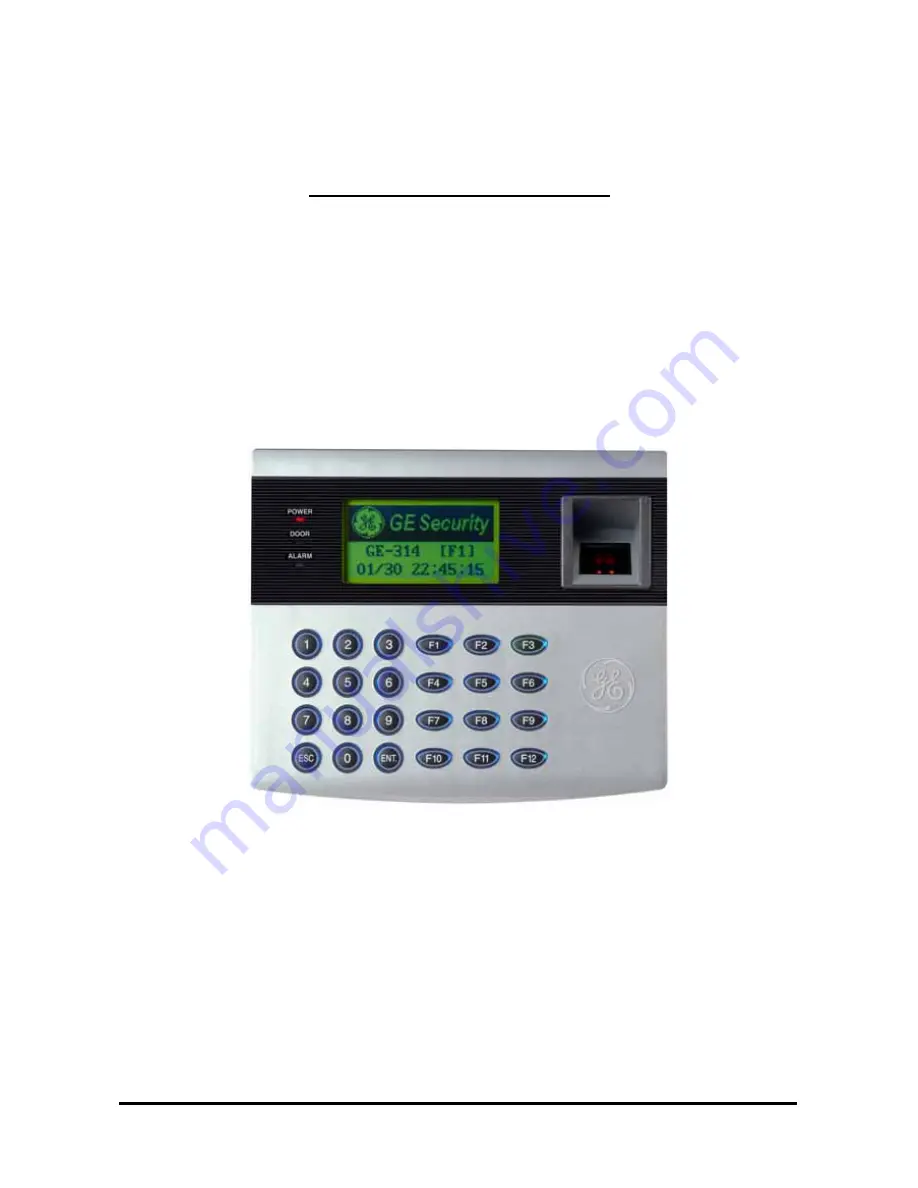
Page 1: ...OPERATING MANUAL FINGERPRINT ACCESS CONTROLLER MODEL GE314 ...

Page 2: ...N TABLE Page 13 4 2 CHECK POINT DURING THE INSTALLATION Page 13 4 2 1 TERMINATION RESISTOR Page 13 4 2 2 HOW TO CONNECT TERMINATION RESISTOR Page 14 4 2 3 GROUND SYSTEM Page 14 4 2 4 REVERSE DIODE CONNECTION Page 15 5 INSTALLATION Page 15 5 1 WALL MOUNT DRAWING Page 15 5 2 BACKUP BATTERY SWITCH Page 16 5 3 SYSTEM INITIALIZATION Page 16 5 4 WALL MOUNT INSTALLATION Page 17 6 WIRING Page 17 6 1 POWER...

Page 3: ... SETTING CHANGES Page 28 9 1 F1 SETUP MENU Page 29 9 2 F2 SETUP MENU Page 33 9 3 F3 SETUP MENU Page 37 9 4 F4 SETUP MENU Page 42 9 5 F5 SETUP MENU Page 47 9 6 F6 SETUP MENU Page 50 9 7 F7 SETUP MENU Page 53 9 8 F8 SETUP MENU Page 56 9 9 F9 SETUP MENU Page 59 APPENDIX Page 61 A THE RELATION BETWEEN INPUT AND OUTPUT DEFAULT Page 61 B TROUBLE SHOOTING Page 63 FCC REGISTRATION INFORMATION Page 67 WARR...

Page 4: ... Do NOT set this product near heaters or any thing that produces heat There may be a risk of fire Be ALWAYS careful not to short circuit any part of the circuitry with tools like a screwdriver There may be a risk of fire or heavy damage of the unit ON MAINTENANCE Do NOT use any kind of liquid for cleaning There may be a risk of electric shock fire or heavy damage of the unit Use air spray if neede...

Page 5: ...rayed onto the product In this case cut the power off first B The product seems to be operating abnormally C The unit exhibits a distinct change in performance D The unit has fallen to be broken down or damaged on its case Repairing costs can be charged for troubles caused due to improper handling or negligence of users or the operator 5 ...

Page 6: ...t button motion detector door contact sensor and existing alarm system to prevent unauthorized access The GE314 has a door relay to control the door lock and an alarm relay to warn any error The graphic LCD display supports 6 different languages so that the unit can be operated anywhere in the world All setup menus can be programmed through the front keypads or via Windows based software program T...

Page 7: ...Mode Fingerprints Only Mode Up to 500 Users only Identification Mode Proximity ID PIN Fingerprints Password Mode Proximity ID PIN Password Fingerprints Mode FAR False Acceptance Rate 0 001 FRR False Reject Rate 0 1 Fingerprint Scanner Optical Scanner LED Lighting Resolution of Scanner 500dpi CMOS CCD 356 x 292 pixels 1 1 Verification Time 1 sec 1 N Identification Time 3 sec if ID found Up to 500 F...

Page 8: ...he unit receives card ID numbers from the proximity readers and determines whether or not to unlock the door When an input signal is entered for example from a Sensor activated or an Exit button pressed the controller generates and logs an appropriate response by input signals All events are stored into the memory buffers and sent to the host computer The access controller is a true stand alone de...

Page 9: ...oliday schedule 02 linked to time schedule 01 Holiday schedule 01 linked to time schedule 03 Forced Door Open Alarm When the door is opened by force the door contact sensor will be activated For this application you have to install the door contact sensor and properly set the door contact time and outputs to the alarm devices The Forced Door Open Alarm will be generated until the alarm is cleared ...

Page 10: ...Panel LCD Module LCD module display GE314 status System Operation Status LED When the power is applied to GE314 the red LED is turned on When the Relay 1 is operated the green LED is turned on When the Relay 2 is operated the yellow LED is turned on 24 key pad You can operate GE314 manually by using the key pad Function key The GE314 has 12 Function keys F1 F12 10 ...

Page 11: ... A Gray wire RS485 RTX RS485 B Blue wire RS232 TX TXD Red wire with white stripe RS232 RX RXD Black wire with white stripe RS232 GND GND Black wire CNN 3 INPUT OUTPUT TTL OUTPUT 1 TTL 1 WD0 Brown wire TTL OUTPUT 2 TTL 2 WD1 Yellow wire Aux Input 1 IN 1 Pink wire Aux Input 2 IN 2 Cyan wire Wiegand DATA 0 DATA 0 Green wire Wiegand DATA 1 DATA 1 White wire CNN 4 INPUT OUTPUT Door RELAY NC NC 1 Gray w...

Page 12: ...th red stripe Alarm RELAY COM COM 2 Brown wire with white stripe Alarm RELAY NO NO 2 Blue wire with white stripe Exit Button EXIT Orange wire Door Sensor CONTACT Purple wire CNN 5 TCP IP RJ45 CONNECTOR 4 INSTALLATION TIPS CHECK POINT 4 1 CHECK POINT BEFORE THE INSTALLATION 4 1 1 CABLE SELECTION Figure System Installation Layout 12 ...

Page 13: ...nsmission line The decision whether or not to use termination resistors should be based on the cable length and data rate used by the communication system For example if you use 9 600 baud rate and 1 200m length of cable the propagation velocity of cable is 0 66 x speed of light This value is specified by the cable manufacturer if we assume the reflections will damp out in three round trip up and ...

Page 14: ...will be a current flow through the shield wire when the voltage level of both ends of shield wire is not equal and this current flow will create noise and interfere to communications For the good grounding we recommend to connecting ONLY one end of shield wire of communication cable to grounding system If you find earth ground nearby then connect one end of shield wire to earth ground If you do no...

Page 15: ...ductor is turning on and off If you do not connect reverse diode the surge voltage will transfer and damage to the electronic circuit of the controller It is strongly recommended to add a reverse diode between the inductor coils to absorb this surge voltage Figure Reverse Diode connection 5 INSTALLATION 5 1 WALL MOUNT DRAWING Unit mm Figure Wall Mount Layout 15 ...

Page 16: ...l RTC Date and Time data during power failure Figure SWITCH SETTING Figure SWITCH LOCATION 5 3 SYSTEM INITIALIZATION After the all installation and connections are completed press and hold the Initialize button and put the power 12V DC to GE314 The LCD will first display Initialize OK 0 No 1 Yes Press 1 key if you want to initialize the system After all Initialization process is completed the syst...

Page 17: ...re of DC 12V power Supply to the Red wire 2 Connect GND wire of DC 12V power Supply to the Black wire 6 2 INPUT CONNECTION Exit Button Connection 1 Connect one wire from an Exit Button to the Orange wire 2 Connect the other wire from the Exit Button to the GND Door Contact Sensor Connection 1 Connect one wire from a Door Contact Sensor to the Purple wire 2 Connect the other wire from the Door Cont...

Page 18: ... Device Connection Alarm Relay 1 Connect COM wire of Alarm Relay the Brown wire with white stripe to 12V 2 Connect NO wire of Alarm Relay the Blue wire with white stripe to wire of Alarm device 3 Connect GND port to wire of Alarm device Figure Door Lock Alarm Device Connection CAUTION Must add REVERSE DIODE as shown above DIODE Fast Recovery DIODE current min 1A 1N4004 1N4007 or similar 6 4 EXTERN...

Page 19: ...low the instructions 1 Connect RS232 TX Red wire with white stripe to the pin 2 RXD of the 9 pin connector 2 Connect RS232 RX Black wire with white stripe to the pin 3 TX of the 9 pin connector 3 Connect GND Black wire to the pin 5 of the 9 pin connector 4 Plug in the 9 pin female connector to COM1 or COM2 Port of the host PC 5 Install and run GE314 Application Software Figure RS 232 COMMUNICATON ...

Page 20: ...s required to use RS485 communication between multiple GE314 and a host PC Please follow the instructions First you have to connect all RS485 port of GE314 in parallel max 32 x GE314 Units 1 Connect RS485 RTX Grey wire of one GE314 to RS485 RTX Grey wire of another GE314 2 Connect RS485 RTX Blue wire of one GE314 to RS495 RTX Blue wire of another GE314 3 Set a different COMM ID for each GE314 Seco...

Page 21: ...AN cable of the network system to RJ45 jack of the GE314 2 If you install multiple GE314 and only one TCP IP port is available you may connect one GE314 to TCP IP then connect all GE314 units to RS485 multiple communication shown above 3 Set a different COMM ID for each GE314 4 Install and run the GE314 Application Software Figure TCP IP Communication between multiple GE314 and a host PC 21 ...

Page 22: ...he SETUP MENU first To do so press 0 key eight times Default Master ID 00000000 and ENT key from the Keypad You now entered to the SETUP MENU There are 9 SETUP MENU and you first get into F1 SETUP MENU You can move to another SETUP MENU by pressing F1 key to F9 key button For example if you want to go to F2 SETUP MENU then press F2 key for F5 SETUP MENU then press F5 key and so on There are severa...

Page 23: ... TIME SETTING Select SET DATE TIME in the F2 SETUP MENU and enter Year Month Date Hour Minute Second Day Total 15 digits as shown below The LCD will display the new Date and Time after the time setting is completed but the year and day will not be displayed GE314 has a 24 hours system and day codes are 1 for Sunday 2 for Monday 3 for Tuesday 4 for Wednesday 5 for Thursday 6 for Friday and 7 for Sa...

Page 24: ...7 5 ID REGISTRATION You can register the User ID into the GE314 Select F4 SETUP MENU REGISTRATION and follow the steps below 1 Registration by Card 2 Registration by Key 24 ...

Page 25: ... Only Mode Time Schedule Setup on the F5 SETUP MENU If you want to access the door anytime for the cardholder then enter the default Time Schedule code 00 for the value 5 TB TB is the Time Schedule code 00 10 for the Reader 2 Exit Reader When you present the c Time Schedule code entered to TB To setup the Time intervals for each Time Schedule code refer to the Time Schedule Setup on the F5 SETUP M...

Page 26: ... nt 3 hen you enroll or verify y place your finger to the scanner correctly To setup Output operating time for each l 0 or 1 Level 1 2 Level 2 4 Level 4 1 ngerprint Usage Flag 1 digit You can assign the user who uses fingerprint or 0 User without Fingerpri 1 User with Fingerprint How to put your finger to the scanner W our fingerprint please Figure How to put your finger to the scanner 26 ...

Page 27: ...e Exit button is pressed the Door Relay 1 Alarms When an unregistered card is read or his her fingerprint is not verified the access is denied and the Alarm Relay 2 will be activated for 3 seconds with the Yellow LED on 8 2 DEFAULT SETTING will open for 3 seconds with the Green LED on When you operate the system for the first time or the system initialized the factory setting values default ory Yo...

Page 28: ...ve to another SETUP MENU by pressing F1 key to F9 key button For example if you want to go to F2 SETUP MENU then press F2 key for F5 SETUP MENU then press F5 key and so on There are several SUBMENU on each SETUP MENU and you can scroll up and down to SUBMENU by pressing 4 and 6 key on each SETUP MENU If you don t press any key for 60 seconds or if you press ESC key GE314 will exit the SETUP MENU a...

Page 29: ...29 9 1 F1 SETUP MENU 9 1 1 VERSION CHECK The Firmware Version of the GE314 displays on the LCD Press 4 or 6 key to have a look for other menus on F1 SETUP MENU ...

Page 30: ... ground level The first two tests are for the output relays Door Relay and Alarm Relay test You can hear the mechanical sound of relays and LED will blink Following two tests are for TTL 1 and TTL 2 output testing The last test is for the Internal Buzzer test and you can hear two beep sounds The LCD will display all characters on the screen When the test is done the LCD will show Last Update Press...

Page 31: ... is and ESC key is on the LCD LCD will display Scanning for reading the cards Present the card to one of the readers When the reader successfully read the card LCD will display Reader number and 8digit card number on the LCD If the Data Memory has problems LCD will show the memory block number with Memory failure message In this case contact manufacturer for technical support 31 ...

Page 32: ...on test connect RS232 RX and RS232 TX wires together This test is a loop test and GE314 sends a character to RS232 TX and check whether the RS232 RX receive the same character or not If you have an error contact manufacturer for technical support 32 ...

Page 33: ...9 2 F2 SETUP MENU 33 ...

Page 34: ...ample 200302101330152 Feb 10 2003 13 30 15 Monday Note READER 1 is built in proximity reader in the unit ID PIN ONLY The door is accessible by just presenting the proximity card or Press the ID Number ID F P P W The door is accessible by presenting a card and verifying Fingerprint or Password ID P W F P The door is accessible by presenting a card and verifying Password and Fingerprint 34 ...

Page 35: ...ddress for each unit in the loop This function is for USE UNUSE the keypad inputs for the Reader 1 The default setting is UNUSE the keypad inputs If you want to access the door by entering the user ID by keypad set this mode USE You have to set this mode USE when the unit is operating with Password Note READER 2 is an external Exit reader of the unit ID PIN ONLY The door is accessible by just pres...

Page 36: ...on error and you have to set same Baud Rate for the same communication network If you have communication problem please check followings Check Communication Address for both GE314 and the host PC Software Check Baud Rate for both GE314 and host PC Check Communication Port and Cable Check COM port setup of the host PC Parity None Data Bit 8 bit Stop Bit 1 bit 36 ...

Page 37: ...9 3 F3 SETUP MENU 37 ...

Page 38: ...GE The user ID number will be displayed on the LCD with text message Default setting is MESSAGE only You can select whether you will use event memory or not When you select USE and in case of an event memory GE314 generates an error message and keeps all events stored in the memory When you select UNUSE GE314 will not generate an error and new event overwrite into the event buffers If you use GE31...

Page 39: ...nit to 1 SEC Set Door Relay DR Output Time to 03 x If you want to activate Door Relay Relay 1 DR for 0 5 second you have to set as follow e Unit to 0 1 SEC Set Door Relay DR Output Time to 05 E 9 Output Time Schedule ID is to unlock the do or when the first user grants the access during the Time Interval of the Time Schedule The door will be locked just after the Time Interval period is over UNUSE...

Page 40: ...installed Exit Reader Do not se you installed Exit Button You must install GE314 for entry and Exit Reader for Exit UNUSE Anti pass Back mode OFF USE Anti pass Back mode ON ess only one time whatever the Anti pass Back flag is ALL FLAG RESET Allow the acc If you are in Duress condition enter 2 digit Duress Password and press ENT key prior to present the card Door will be opened as normal but the D...

Page 41: ... is not closed after the door open time Door Relay time 01 98 Alarm if the door is not closed after the door open time and over the alarm delay time 01 98s 99 No Door Open Alarm s a Reader and sends 26bit Wiegand Output through two TTL output ports Press ENT key and select USE by pressing 4 or 6 key then press ENT key for setting UNUSE Normal TTL outputs will be activated USE 26bit Wiegand output ...

Page 42: ...9 4 F4 SETUP MENU 9 4 1 ID REGISTRATION 1 Registration by RF Card 42 ...

Page 43: ...TUP MENU If you want to access the door anytime for the cardholder then enter the default Time Schedule code 00 for the value 5 TB TB is the Time Schedule code 00 10 for the Reader 2 Exit Reader When you present the 2 Registration by card to the Reader 2 the cardholder is only allowed the access of the door during the Time intervals of the Time Schedule code entered to TB To setup the Time interva...

Page 44: ...r to the Output Setting on the F7 SETUP MENU 2 Level 2 9 4 2 ID DELETION 9 LV LV is the Output Operating Level for the cardholder Output T 0 or 1 Level 1 3 Level 3 4 Level 4 10 FP FP is the Fingerprint Usage Flag 1 digit You can assign the user who uses fingerprint or not 0 User without Fingerprint 1 User with Fingerprint Registered ID will be deleted in the controller by presenting the card or in...

Page 45: ...or Reader 1 MA and Reader 2 MB the output level E gistered user ID FIRST ID message LAST ID message w isplays the ID on the bottom of the list LV and usage of Fingerprint FP for this user MPTY message will be displayed if there is no re will be displayed if the LCD displays the ID on the top of the list ill be displayed if the LCD d ASTER ID REGISTRATION MAS RATION BY CARD 45 ...

Page 46: ... stored in the unit The default Master ID 01 is 00000000 and Fingerprint is not used There are total 10 Master IDs from 01 to 10 can be stored in the unit 9 4 6 EVENT COUNT This menu displays the total number of Event stored in the memory It automatically increases the count when the Event is stored in the memory The LCD shows total 12345 Events are stored in the memory Total number of Event is 20...

Page 47: ...9 5 F5 SETUP MENU 9 5 1 TIME SCHEDULE 47 ...

Page 48: ...y to program the time period This system is based on 24 hours system and therefore the time 00 00 and 24 00 is the same time and 12 0 is 12 O clock afternoon Enter hour and minutes for start time and hour and minutes for end time of the Time Interval then press ENT key to store T S to the memory Press ESC key to return to the menu le will 0 There are 10 Holiday Schedule Code available r the users ...

Page 49: ...r Mode 3 RF PW Finger Mode H y Schedule Code and press ENT key to store Holiday Index to the memory Press ESC key to return to the menu There are 3 system operating mode RF Only Mode RF F P Mode and RF PW F P Mode You can setup one of the system operating mode from F2 SETUP MODE R1 MODE SETTING menu However you want to apply different operating mode for a certain Time Interval for all users For ex...

Page 50: ...9 6 F6 SETUP MENU 50 ...

Page 51: ... 5 TAMPER ALARM 00 99 99 99 99 6 DURESS ALARM 00 00 00 00 00 7 OUTPUT TIME SCHEDULE 00 00 00 00 00 8 INPUT TIME SCHEDULE 00 00 00 00 00 9 INPUT TYPE 00 00 00 00 00 You can program OUTPUT activating time when the EXIT button pressed The value put here is value x second when the Time Unit set to 1 second and value 10 second when the Time Unit set to 0 1 sec You can set the time from 00 to 98 seconds...

Page 52: ...sor Input T S Code I1 Aux Input 1 T S Code I2 Aux Input 2 T S Code TP Tamper Switch Input T S Code You can link a T S Code to each Input The default T S Code is 00 which means no T S is applied to the Inputs This setting is very useful when you want to activate PIR sensor input for a Time Interval Press ENT key to link a T S Code to the Input then enter 2digit T S Code for each Input EX EXIT Butto...

Page 53: ...9 7 F7 SETUP MENU 53 ...

Page 54: ...er 2 ID OK LV4 05 00 00 00 00 12 Reader 2 ID Error 00 03 00 00 00 13 Reader 2 T S Error 00 03 00 00 00 14 Reader 2 APB Error 00 03 00 00 00 You can program OUTPUT activating time when the user ID is granted the access from the Reader 1 The value put here is value x second when the Time Unit set to 1 second and value 10 second when the Time Unit set to 0 1 sec This Output Time is applied for the us...

Page 55: ...pplied for the users registered with Level 2 output This Output Time is applied for the users registered with Level 3 output 9 7 11 OUTPUT SETTING FOR READER 2 ID OK LEVEL 4 This Output Time is applied for the users registered with Level 4 output 9 7 12 OUTPUT SETTING FOR READER 2 ID ERROR 7 13 T 7 14 T ser is APB error to Reader 2 th 2 out This Output Time is applied fo d wi 3 o This Output Time ...

Page 56: ...eeded First time installation or resetting in the event of a malfunction CAUTION Initializing will erase all stored data in the memory Press the 1 key to initialize or 0 key to cancel the operation The WAIT message appears while the system is being initialized After the initialization GE314 will return to the Setup menu 56 ...

Page 57: ...to change ID COUNT you can clear the event memory in this menu Press ENT key then press 1 key to clear event memory or 0 key to cancel the operation CAUTION Before you clear the events make sure that the stored events is not necessary to upload to the host PC otherwise you may lose important data When you want to delete all Master IDs you can clear all Master IDs from the memory Press ENT key then...

Page 58: ...ar all T S make sure that the stored T S is no longer used otherwise you may lose all stored T S in the memory When you want to delete all Default setting value you can clear them from the memory Press ENT key and press the T S or 0 key to cancel the operation CAUTION Before 1 key to reload all default setting value clear all you clear all Default setting value Reader mode Board ID etc make sure t...

Page 59: ...ister two fingerprints for one user ID Default is UNUSE Fingerprint Mode is higher False Acceptance Rate FAR measured In DUAL But Dual 9 In ADAPTIVE MODE scanning quality is better than normal mode and also it checks latent finger But scanning speed is longer than normal mode Default is USE 59 ...

Page 60: ...er to the scanner Automatic Touch Sensor is optional purchase This menu displays the total number of registered user ID It automatically counts when you register or delete er IDs The LCD shows total 123 user IDs registered in the memory Total number of user IDs is 1 000 user IDs standard or optional 2 000 4 000 user IDs can be stored in the unit us 60 ...

Page 61: ...hat each input 1 Exit button 5 operation has to be applied Index No 9 The value indicates the type of each input 1 Exit button 5 operation The 00 is NO Normal Open type The 01 is NC Normal Close type OUTPUT INPUT Door Relay DR Alarm Relay AR TTL 1 T1 TTL 2 T2 Buzzer BZ 1 EXIT BUTTON 03 00 00 00 00 2 DOOR CONTACT 00 99 00 00 00 3 AUX Input 1 00 00 00 00 00 4 AUX Input 2 00 00 00 00 00 5 TAMPER ALAR...

Page 62: ...OK LV2 05 00 05 00 05 00 5 Reader 1 ID Error 00 03 00 00 00 6 Reader 1 T S Error 00 03 00 00 00 7 Reader 1 APB Error 00 03 00 00 00 8 Reader 2 ID OK LV1 03 00 00 00 00 9 Reader 2 ID OK LV2 05 00 00 00 00 10 Reader 2 ID OK LV3 05 00 00 00 00 11 Reader 2 ID OK LV4 05 00 00 00 00 12 Reader 2 ID Error 00 03 00 00 00 13 Reader 2 T S Error 00 03 00 00 00 00 00 00 3 Reader 1 ID OK LV3 00 00 00 4 Reader 1...

Page 63: ...ght have been changed or components are defective Solution 1 Try changing the Master ID through the application S W It ll be changed to 00000000 2 When it is not feasible initialize the unit as following After the all installation and connections are completed press and hold the Initialize button and put the power 12V DC to GE314 The LCD will first display Initialize OK 0 No 1 Yes Press 1 key if y...

Page 64: ... no key in or reading card within 60 The Setup mode suddenly goes back to the Normal operating mode Cause T r Solution In the Set seconds Keeps making buzzer sound beep beep beep or beeeeeeeep olution 1 Check the door status It occurs in case that the door is o open time Check the door contact sensor type it should be NO type Check in 7 OUTPUT T S of F6 the ten Ti schedule code is set between 01 u...

Page 65: ...all times put in 00 ACCESS DOOR ERR message shows when the RF ID card is read Cause Incorrect user setting or false of internal circuit Solution 1 If it was a properly operating unit before there has been an electric shock that damaged the internal during its registration ontroller has two reader ports define RD door for the user to be allowed to access nly 2 Reader 1 2 both 0 or 3 t reader1 If it...

Page 66: ...ty bit NONE Data bit 8bit Stop bit 1bit 2 Check the line connection for communication RS232 RS485 mono Solution ault is the same as the setting on the S W GE313 PC GE314 RS485 232 Converter PC RX TX RTX RTX TX RX RTX RTX GND GND The RS232 cable from the converter RS485 Multi Drop GE314 GE314 RS485 232 Converter PC RX RX TX RX RX TX The RS232 cable from the converter 3 In case of setting RS485 comm...

Page 67: ...e user is encouraged t corre one or more of the following measures 1 Reorient or relocate the receiving antenna 2 Increase the separation between the equipment and re 3 Connect the equipment ut ther 4 Consult the dealer or an technician for help FCC REGISTRATION INFORMATION anges or modifications in construction of this device which are not expressly approved b r compliance could void the user s a...

Page 68: ...aster idteck com Web site www idteck com Technical Support in korea 684 1 Deungchon dong Gangsuh SEOUL 157 030 KOREA Tel 82 2 2659 0055 Fax 82 2 2659 0086 E mail techsupport idteck com Hotline 82 16 604 8965 Customer support 82 17 340 4170 R D Please use the original container or pack the unit s in a sturdy carton with sufficient packing to prevent damage include the following information 1 A proo...

Page 69: ...S 232 Com Input Output Power Keypad Card Reading RS 422 Com 1 Engineer Comment Others RS 232 Com Input Output Power Keypad Card Reading RS 422 Com 2 Engineer Comment Others RS 232 Com Input Output Power Keypad Card Reading RS 422 Com 3 Engineer Comment Others RS 232 Com Input Output Power Keypad Card Reading RS 422 Com 4 Engineer Comment Others RS 232 Com Input Output Power Keypad Card Reading RS ...

Page 70: ...05R XXXXXXXXX Keypad RS 42 1 Engineer C Write problem to be detailed omment Others others RS 232 Com Power Ke Card Reading Input Output ypad RS 422 Com omment Others RS 232 Com Input Output Po Ke wer ypad Card Reading RS 422 Com 3 E C ngineer omment Others RS 232 Com Input Output Po Ke wer ypad Card Reading RS 422 Com 4 E C ngineer omment Others RS 232 Com Input Output Po Key RS 422 Com wer pad Ca...

Page 71: ...A S REQUEST FORM ORIGINAL 71 ...

Page 72: ...A S REQUEST FORM SAMPLE 72 ...

Page 73: ...MEMO 73 ...

Page 74: ... manual are subject to change without notice at any time 5F Ace Techno Tower B D 684 1 Deungchon Dong Fax 82 2 2659 0086 E mail webmaster idteck com Gangsuh Gu Seoul Korea 157 030 Tel 82 2 2659 0055 MAR 2005 Copyright 2004 IDTECK Co Ltd ...

Reviews: