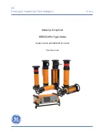
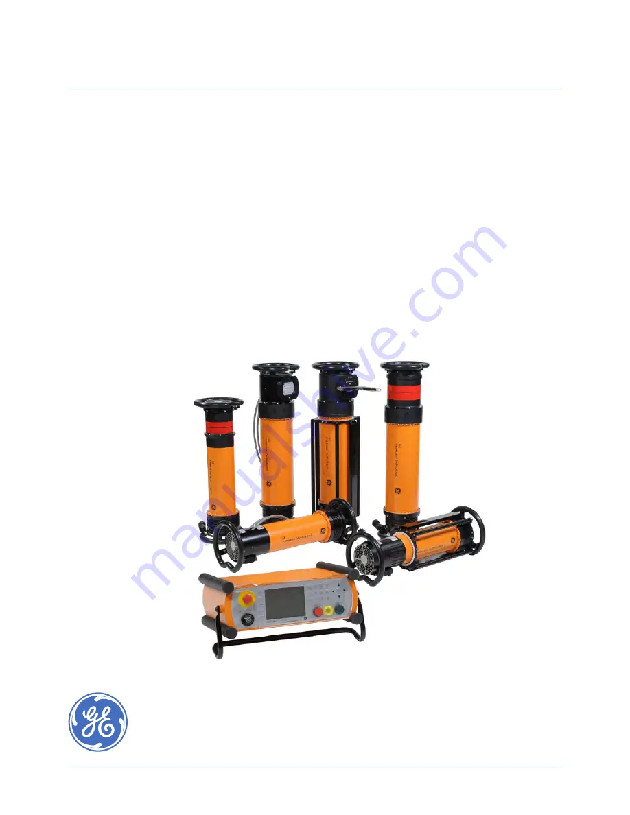
background image

GE

Sensing & Inspection Technologies

X-ray

Industry X-ray Unit

ERESCO MF4 Type Series

Digital control unit ERESCO MF4 control

Operating manual

Summary of Contents for ERESCO 160 MF4-R

Page 1: ...GE Sensing Inspection Technologies X ray Industry X ray Unit ERESCO MF4 Type Series Digital control unit ERESCO MF4 control Operating manual ...

Page 2: ...mbH Reference hi er gu Date 08 24 2016 File 37020GB F Betriebsanleitung_ErescoMF4 indd Printed in Germany 2016 GE Sensing Inspection Technologies GmbH reserves the right to technical modifications without prior notice No part of this publication may be reproduced stored in a retrieval system or transmitted in any form or by any means electronic mechanical photocopying recording or otherwise withou...

Page 3: ...Manual 12 2 1 Installation of the Unit 12 2 1 1 Operation with optional warning flash lamp 15 2 1 2 Operation with connected door contacts 15 2 2 Taking into operation 16 2 2 1 Mains connection 16 2 2 2 Stand by 16 2 2 3 Display modes 17 2 2 4 Ready for operation and warm up 19 2 2 5 Extended Warm up Mode 23 2 3 Setting the Operating Parameters 25 2 3 1 Exposure time 25 2 3 2 kV setting 26 2 3 3 m...

Page 4: ...10 Warm up history 48 11 Dimension unit 49 12 Beeper 50 13 Exposure Calculator 51 14 Memory location 53 4 Interlock Mode 54 5 Protective Devices 56 6 Fuses and pin assignment at ERESCO MF4 control 57 7 List of Messages 59 8 Maintenance 63 8 1 Ideal operation for X ray tubes 63 8 2 Water cooling pump WL 1001 optional 64 8 3 Checking the Automatic Shut Off of the Flow Rate Monitor optional 65 8 4 Ch...

Page 5: ...t ERESCO MF4 control 68 11 2 ERESCO 32 MF4 C 69 11 3 ERESCO 42 MF4 and ERESCO 42 MF4 W 69 11 4 ERESCO 52 MF4 CL 70 11 5 ERESCO 65 MF4 and ERESCO 65 MF4 W 70 11 6 ERESCO 160 MF4 R and ERESCO 160 MF4 RW 71 11 7 ERESCO 280 MF4 R and ERESCO 280 MF4 RW 72 11 8 ERESCO 300 MF4 R 73 Index 74 Appendix 1 Exposure Diagrams 75 Appendix 2 Connection Diagram 81 Appendix 3 Image Quality of Test Specimen EN 462 8...

Page 6: ...current Danger Danger by ionizing rays X ray radiation Caution Warning of a Danger zone Indication of unauthorised entry or intervention Caution Danger of crushing Caution Laser radiation hazard Indication of special information following instructions Symbol for hazardous waste segregation 1 Safety Information X ray units that are used in industrial materials testing radiography basically require ...

Page 7: ...pact of batteries and rechargeable batteries on the environment and on human health For proper recycling you can return this product or the batteries or rechargeable batteries it contains to your supplier or to a designated collection point Some batteries or rechargeable batteries contain toxic metals that pose serious risks to human health and to the environment When required the product marking ...

Page 8: ...rial such as lead in sufficient thickness This diaphragm can be either provided by the supplier or by the customer 4 Frequently the cheapest und most convenient radiation protection is achieved by keeping the distance from the radiation source as large as possible In case of mobile X ray units make use of the full length of the connecting cable between the radiating unit and the control All automa...

Page 9: ...creased from zero to the preselected value in the case of all GE Sensing Inspection Technologies control units 9 Always remember to cover the rear side of the film with an additional lead plate when taking shots By doing so you substantially reduce general radiation level and additionally protect the film against stray radiation that reduces contrast 10 Please always remember that so long as X ray...

Page 10: ...isions for the operation of an X ray tube and legal radiation protection provisions have to be observed and upheld There is danger of sustaining injuries in case of improper operation or manipulation of the components 1 5 Authorised Users Only authorised persons are allowed to operate the unit Operators must be at least 18 years old valid for the Federal Republic of Germany Relevant national regul...

Page 11: ...cified protective clothing at the installation site 1 7 Safety Measures at the Installation Site Always use the shielding equipment available at site Structural conditions can quite often be used to enhance safety You should clearly demarcate and label control areas properly ATTENTION Increased earth leakage current The earth leakage current of this X ray equipment is higher than 3 5 mA According ...

Page 12: ...he plug connections are non interchangeable CAUTION Orange mains cable with Schuko plug 230 V AC only Grey mains cable without Schuko plug 115 V AC only 2 Operating Manual Preliminary remarks The following Operating Manual does not contain instructions on adherence to obligatory radiation protection It is the responsibility of the user to equip operating personnel with dosimeters and to monitor th...

Page 13: ... 1 If you have any further questions please contact GE Sensing Inspection Technologies GmbH Numeric keypad EMERGENCY STOP button pull out to unlock X RAY OFF button High voltage pilot lamp X RAY ON button Function keys Key operated switch Display Fig 2 Front view of the digital control unit ERESCO MF4 control without covers Arrow keys and acknowledgement Fig 3 Digital control unit ERESCO MF4 contr...

Page 14: ...the radiating unit from overheating at operation in closed rooms or in radiation protection cabinets please ensure the following minimum distances to walls and the minimum air flow rate Room with auxiliary fan Room without auxiliary fan air flow 500 m3 hour 18 ft hour Valid for all details minimum values Fig 4 Radiating unit for operation in closed rooms or radiation protection cabinets ...

Page 15: ...voltage cannot be switched on 2 1 2 Operation with connected door contacts When the safety door contacts are to be connected use the supplied eyebolt to remove the short circuit plug for the door contact from socket X2 at the plug hutch NOTE If door contact 1 has been opened door contact 2 should also be opened Both door contacts must be closed before the unit is ready for operation again Short ci...

Page 16: ... the unit is now in STAND BY mode The supply to the control unit computer and a possibly connected coolant pump is switched on Input via the keypad is not possible However a status request via the serial interfaces is possible The following mask appears on the display Fig 6 Mains connection 1 PE N 160 V 253 V AC max 13 A 50 60 Hz orange cable resp 1 PE N 80 V 127 V AC max 20 A 50 60 Hz grey cable ...

Page 17: ...he unit is now ready for operation and one of the following masks appears on the display Use the F1 key to change the function key arrangement Use key F2 to show or hide the Measured values The following values are displayed in the Measured Values section Line power ERESCO MF4 control display only when high voltage is switched on Rectifier temperature in ERESCO MF4 control Cascade temperature radi...

Page 18: ...F1 function key arrangement changeover Key F2 kV input Key F3 mA input Key F4 exposure time input Key F5 power mode Key F1 function key arrangement changeover Key F2 save programs Key F3 open programs Key F4 call warm up program Key F5 exposure calculator Key F1 function key arrangement changeover Key F2 show or hide measured values Key F3 not used Key F4 Enter Film Focal Distance Key F5 not used ...

Page 19: ...erated switch at the operation module from STAND BY to ON The unit is now ready for operation Depending on the last operated tube voltage and the expired operation break the following masks appear on the display If the last operated tube voltage is less than half the nominal tube voltage If the last operated tube voltage is greater than half the nominal tube voltage The operator is provided with t...

Page 20: ...nit subsequently appears After the prompt for starting the unit press the X RAY ON button The remaining warm up time is displayed in the Time left field during the warm up procedure An acoustic signal sounds 2 seconds before the end of the warm up program After the warm up program the following message appears Press the key to confirm the message The operating mask e g manual mode which was select...

Page 21: ...ter this type of technical fault or X RAY OFF the user still has two further attempts to warm up the tube after which warm up is terminated and can only be restarted after a renewed mains ON Fault message example After eliminating the fault the message must be confirmed by pressing the CL key Then and also after pressing the X RAY ON button the following mask appears If the F4 key is pressed the a...

Page 22: ...minated three times the following message appears in the comment line on the display The unit can only be restarted after a renewed mains ON In this case a service technician should be consulted After pressing the F5 key the operating mode used before switching on is shown on the display e g MANUAL mode The warm up program can be called manually as follows Press the F1 key until the symbol appears...

Page 23: ...etups with high energies the extended warm up mode can be used The warm up mask will be called automatically Use the key F1 Mode to change the function key arrangement With keys F1 and F2 or the arrow keys and select the warm up mode RTC Auto The X ray unit can be warmed up from half of the nominal tube voltage up to the maximum tube voltage as described in chapter 2 2 4 EXT The X ray unit will be...

Page 24: ...ay The procedure in case of a shut down by a fault or an uneven operation of the X ray tube is carried out as discribed in section 2 2 4 page 21 and 22 After this type of technical fault or X RAY OFF during the extended warm up mode the user still has four further attempts to warm up the tube After this the warm up will be stopped and can only be restarted after a renewed mains ON If the warm up p...

Page 25: ...ey 2 3 1 Exposure time Press the F4 e key The set point value display of the minutes seconds is displayed inversely Enter the desired exposure time confirm the set exposure time via the OK key and the clock symbol e subsequently appears If 0 is entered as the time the timer is switched off and the high voltage can only be switched on and off via the X RAY ON and X RAY OFF button Special version fo...

Page 26: ...hrensburg 2 3 2 kV setting Press the F2 kV key The set point value of the high voltage is displayed inversely Enter the desired kV value and press the OK key to accept the set kV value 2 3 3 mA setting Press the F3 mA key The set point value of the tube current is displayed inversely Enter the desired mA value and press the OK key to confirm the set mA value ...

Page 27: ...ction 2 3 according to the exposure diagram see appendix in the following order Example 1 kV 90 2 mA 4 5 3 min 5 0 For power optimisation press the F5 key P The unit calculates the shortest exposure time that can be achieved with the maximum tube power The shortest exposure time set by the unit is 30 sec NOTE In case of low mains voltage 204 V or 107 V the nominal values cannot be achieved dependi...

Page 28: ...ed on the pre selected high voltage and the respective set parameters The maximum permissible tube current and the appropriate exposure time for the set high voltage are preset with these values The exposure calculator is called as follows Use the F1 key to change the function key arrangement Press the F5 key to call the exposure calculator Press the F2 key to change the function key arrangement a...

Page 29: ...ed according to the inspection task calculation is started by pressing the F4 key The function key arrangement is changed In accordance with calculation of the mA x min product the shortest exposure time for the set kV and mA values is set After pressing the F4 P key the power mode is switched on and a new calculation of the exposure time is automatically executed so that the calculated mA x min p...

Page 30: ...the F1 key it is then possible via the F2 key to save the calculated values as a program as described in section 2 9 By calling the previously saved program as described in section 2 10 it is possible to carry out exposures with the calculated values in program mode To carry out exposures with the calculated values in manual mode the function key arrangement must be changed to standard mode by pre...

Page 31: ...3 NOTE The values describes in chapter 2 3 refer to the standard Film Focal Distance of 700 mm This value can be changed in the setup menu item 13 Exposure Calculator page 52 To switch on the FFD Correction the function key arrangement must be changed by pressing key F1 twice and the key F4 FFD has to be actuated Thereby the Film Focal Distance will be indicated inversely on the right site of the ...

Page 32: ...nsburg After pressing key F1 to change to the parameter view press the button START to start the exposure NOTE In case of low mains voltage 204 V or 107 V the nominal values cannot be achieved depending on the output power The unit then switches off with message 124 reduce power Remedy Reduce the power by approx 20 and increase the exposure time correspondingly ...

Page 33: ...point 04 page 43 6 seconds prior to the end of the exposure time an acoustic signal sounds until the high voltage is switched off Once the exposure time has expired the high voltage will be purposefully reduced to zero and switched off after a short reheat period to discharge the high voltage cascade If technical faults occur during operation the unit will be switched off and the operator will be ...

Page 34: ...ime by pressing the X RAY OFF button The high voltage is reduced to zero before the high voltage supply is switched off In this case the displayed actual value of the exposure time remains at the current value and the exposure can be continued at any time by restarting An exposure time error cannot occur If a new exposure is to be carried out after the manual stop the exposure time must be reset a...

Page 35: ...th 250 program positions of the data source appears which is activated in the setup menu item 14 Memory location Use the arrow keys and to select the desired program position and press the F4 key to save the program NOTE If you attempt to program a program without an exposure time the following message appears 66 Exposure time 0 Press the F5 key to delete the message enter the desired exposure tim...

Page 36: ...sure the existing program is not overwritten Select another program number Press the F4 key to overwrite the existing program the program mode appears on the display It is possible to give each program a name with up to 20 characters The entered program names will not assumed when saving the program into the X ray unit see setup menu item 14 Memory location To achieve this press the F1 key ...

Page 37: ... Numbers are entered via the numeric keypad without pressing the OK key Use the F1 and F2 keys to move the cursor in the entered name If another letter is entered while the cursor is positioned in the name it is entered in front of the highlighted letter Press the F3 key to toggle between upper and lower case letters The CL key always deletes the highlighted letter Press the F5 key to exit the mas...

Page 38: ...e arrow keys and to select the desired program position and press the F4 key to save the program If a program already exists under the desired program number the following message appears Press the F5 key to ensure the existing program is not overwritten Select another program number Press the F4 key to overwrite the existing program the program mode appears on the display ...

Page 39: ...key A list with 250 program positions of the data source appears whitch is active in the setup menu item 14 Memory location Use the arrow keys to select the desired program number possible prog nor 1 to 250 and then press the F4 key to call the selected program The display changes to the program mode When loading programs from the X ray unit see setup item 14 Memory location the name of the progra...

Page 40: ...ress the OK key to accept the set value Press the F1 key to exit the program mode at any time The manual mode re appears with the values of the last operated program mode It is not possible to change parameters in the program mode Only the X RAY ON and X RAY OFF button and the CL key are active If the high voltage is switched off the F1 and F3 key are also active in order to call other programs or...

Page 41: ...ntering the respective number and pressing the OK key e g 01 and OK The current position is displayed inversely You can leave the menues by actuating key F5 at any time 01 Operating hours The operating hours of the digital control and the radiating unit with integrated insert tube are displayed Furthermore the serial number of the connected radiating unit and the integrated insert tube are display...

Page 42: ...F4 keys to select the parameter to be changed and press the F1 and F2 keys to change the parameter Press the OK key to accept the changed value and to select the next parameter After carrying out all the settings and confirming them via the OK key press the F5 key to return to the setup menu 02 Tube data The operating data of the connected tube such as tube code type of radiating unit nominal volt...

Page 43: ...umeric keypad or by pressing the or keys Press the OK key to confirm the new setting Enter 0 to switch off the prewarning time After entering 0 second the password 1483 must be entered to confirm the setting Password input is not required for prewarning time changes above 2 seconds A prewarning time setting of 1 second is not possible CAUTION The prewarning time is designed to protect personnel an...

Page 44: ...The function keypad changes after entering the password 1483 The parameter DD is displayed inversely and can be changed by pressing either the numeric keys or the and keys Press the OK key to accept the new value The next parameter is displayed inversely and can be changed as described before Press the and key to select the next parameters MM YYYY hh mm and ss without accepting the changed value P...

Page 45: ...ware ID The software ID number and date of the software in use are displayed Press the F5 key to exit the display 07 Language The current language is displayed inversely Use the and keys to select one of the displayed languages Press key F4 or the OK key to activate the selected language The setup menu will be displayed again Press the F5 key to exit the menu without changes ...

Page 46: ...both ERESCO MF4 control and radiating unit Use keys F3 and F4 to toggle between the masks Use keys F1 und F2 to select individual lines Displayed are Row 1 port name Row 2 actual state Bit 0 Bit 1 Row 3 location Control X ray unit and hardware device e g H lamp S switch X plug Row 4 no of the message that appeares in the event of an error The corresponding messageisdisplayedinthelowerfield ifthecu...

Page 47: ...ssible related message are always displayed Press the F3 key to call a further mask which in addition to the permanently displayed values see above also shows the following measured values The mains voltage V the cascade temperature C F the gas pressure of the radiating unit bar and the temperature of the power stage C F PresstheF4ekeytocallafurthermaskwhich inadditiontothepermanentlydisplayedvalu...

Page 48: ...ate and time can be requested by pressing the and keys Furthermore it is also displayed whether the buffer battery is empty X or not NOTE If a buffer battery is empty the date and time display is only correct if it has been set correctly after switching on the unit Press the F5 key to exit the menu Press the F2 key to show the first display again with the time and date see above Press the F5 key t...

Page 49: ...perature and the Film Focal Distance FFD are displayed Press the F2 key to display one of the unit of measurements inversely and to change the function key arrangement Use the and keys to change the unit of measurements mm inch C F Press the OK key to accept the changed unit of measurements and to select the next unit of measurements Press the F4 key to display the result of the change Press the F...

Page 50: ...chnologies GmbH Bogenstrasse 41 D 22926 Ahrensburg 12 Beeper The beeper status is displayed Beeper active means The beeper sounds 10 seconds prior to the end of the exposure time Press the F1 key to activate or deactivate the beeper Press the F4 key or the OK key to accept the setting Press the F5 key to exit the menu ...

Page 51: ...vert various materials to the common exposure diagrams for steel and aluminum Press the F4 key to toggle between the masks Use the F2 key to change the keypad arrangement NOTE To compensate differing conditions in the unit or film development set up the correction factors for the standard materials Fe Al and Ti can also be changed Usethearrow keys and or and to select the respective parameter Via ...

Page 52: ...o accept the entry Press the F3 key to call up the default values stored in the unit By using key F4 a further mask appears in which a new default value of the Film Focal Distance can be entered By using the F2 key the function key arrangement will be changed and the FFD value will be displayed inversely After selecting the respective values press the F4 key to accept the values and to display the...

Page 53: ...f this information download display only the data stored in the control will be used The program list including the program names will only be managed in the control module If the active data source is the X ray unit the control module does not log or store any data Upon data access download display the control module accesses the data source on board of the X ray unit and temporarily downloads it...

Page 54: ... before the unit is ready for operation again In order to easily integrate the unit into an safety circuit the short circuit plug must be removed see section 2 1 2 and the external safety circuit connected Short circuit plug with eyebolt Eyebolt For the external safety circuit connection we recommend the ready made door contact cable ID No 7304121 Pin assignment X2 of the potential free contacts a...

Page 55: ...onnected in a way that ensures that both door contact circuits are opened Redundancy means that the circuit status of both door contact circuits is monitored for status correspondence When DC1 is open DC2 must also be open Example X ray room with a charging door and a service door Functions correctly Charging door door 1 Service door door 2 ERESCO MF4 1 4 5 6 DC1 DC2 S1 S2 S3 S4 1 door 2 1 4 5 6 D...

Page 56: ...urrent can temporarily reach extremely high values which cannot always be regulated via an automatic current control In this case the overcurrent cut off responds and immediately interrupts the high voltage supply to protect the X ray tube against consequential damages A restart is only possible after the cascade has been discharged approx 1 2 min 3 The yellow high voltage lamp i located on the fr...

Page 57: ...see Fig 7 Pin assignment X1 mains connection L 1 N 2 PE Jumper between 3 4 for connecting cable orange 230VAC version Jumper between 3 5 for connecting cable grey 115VAC version Pin assignment X2 of the potential free contacts between pin 2 and 3 Prewarning 42 V 1 0 A between pin 7 and 8 High voltage ON 42 V 1 0 A between pin 13 and 14 Mains voltage ON 110VDC 125VAC 1A Pin assignment X2 of the doo...

Page 58: ... 6 and 5 115 V AC max 0 5 A constant depending on the applied mains Pin assignment X4 for the cooling circuit between pin 1 and 4 Signalling contact for the water flow rate monitor between pin 2 and 5 Supply voltage for the water cooling pump 230V AC 4A constant or 115V AC 4A constant depending on the applied mains Pin assignment X5 for the connecting cable Description Pin 1 27V Pin 2 RS485B Pin 3...

Page 59: ...g error 53 High voltage lamp defective The high voltage lamp in ERESCO MF4 is defective ERESCO MF4 55 Relative overcurrent monitoring Fault in the control circuit Tube has drawn in gas The actual tube current value exceeds the pre selected set point value 58 Not programmed Programs have been called for which a program has not yet been generated Operating error 60 Relative undercurrent monitoring F...

Page 60: ...rs The output stage temperature has exceeded 80 C 82 HV prim overcurrent Current to high at the primary side of the high voltage transformer Radiating unit 86 HV contactor faulty Appears when with high voltage OFF the high voltage contactor is not released High voltage contactor 87 Flash lamp faulty Flash lamp defective no flash lamp connected No prewarning time set see set up menu point 05 Short ...

Page 61: ...tor has not been discharged The electronic power switches are defective Voltage monitoring error Control module IGBT chopper 113 Absolute overcurrent monitoring The actual current value has exceeded the generator limit current 10 5 mA for ERESCO 42 MF4 6 5 mA for ERESCO 65 MF4 Control circuit error tube has drawn in gas Radiating unit 116 Warm up terminated after 3 attempts The warm up program has...

Page 62: ...g the radiating unit in power mode To achieve this the following operating parameters are required ERESCO 160 MF4 R 60 kV 10 mA 10 min ERESCO 200 MF4 R 60 kV 10 mA 10 min ERESCO 42 MF4 90 kV 10 mA 10 min ERESCO 32 MF4 C 60 kV 10 mA 10 min ERESCO 65 MF4 150 kV 6 mA 10 min ERESCO 52 MF4 CL 100 kV 6 mA 10 min ERESCO 280 MF4 R 100 kV 3 4 mA 10 min ERESCO 300 MF4 R 150 kV 6 mA 10 min After successful o...

Page 63: ... and cannot be prevented the vacuum is continuously reduced in the X ray tube As a result the free molecules in the reduced vacuum are ionised when a voltage is applied and the tube cannot be operated up to the nominal output The potential difference can result in sudden flashovers in the ionising channel To increase the service life of the X ray tube regularly warm up or condition the tube In a p...

Page 64: ... cause coolant flocculation and total failure of the circulation pump if necessary empty the water cooling circuit and refill it with a new mixture of GlycoShell and water It is extremely important to observe the colour The following cooling water colours are permissible Clear dark blue green Any other colours are not permissible e g red brown black For temperatures up to 25 C we recommend a ratio...

Page 65: ...tal control unit ERESCO MF4 control 33 Cooling system failed The tap symbol on the display flashes until the fault has been eliminated and the high voltage cannot be switched on If these maintenance instructions are not observed it may result in the X ray tube head not being cooled which can cause unit failure and possible high resulting costs 8 4 Checking fail safe operation of the optional warni...

Page 66: ...esults in message 53 High voltage lamp defective and the high voltage is immediately switched off Proceed as follows to replace the high voltage lamp 1 Unscrew the yellow lamp cover 2 Preferably use the lamp extractor size T1 to remove the defective lamp with holder Alternatively Rubber hose long nosed pliers forceps Lamp extractor ID No 9456540 Bulb ID No 9030420 3 Lamp covers are installed in re...

Page 67: ...ructions of the operator should be designed to reduce any possible risks during work It is recommended that the X ray device and associated components be entrusted to the manufacturer for correct disposal control desks and power module and the like be entrusted to a certified disposal company for correct disposal The X ray tube assembly contains beryllium and should not be disposed of as standard ...

Page 68: ...splay transreflective backlight Graphic display 320 x 240 pixels Available languages 19 Character sets 4 European ISO Japanese Chinese Cyrillic Pre programmable exposure programs max 250 Serial interface RS232 1 Safety circuits 2 EMERGENCY STOP button 1 Key operated switch with 3 positions OFF STAND BY ON Mains requirements 1 PE N 160 V 253 V AC max 13 A with grounded neutral 1 PE N 80 V 127 V AC ...

Page 69: ...lass IP 65 Tube head diameter 160 mm Current and voltage stability 1 Power consumption max 1 6 kVA without water cooling pump only 42MF4 W Min cooling water flow rate 2 5 l min Max cooling water pressure 10 bar Cooling water quality Drinking water Hose connection Ø 11 mm 2 4 6 8 10 0 12 11 2 ERESCO 32 MF4 C Nominal voltage 5 200 kV Tube current 0 5 10 mA 3 mA 200 kV Continuous operating power 600 ...

Page 70: ... 4 kVA If the panoramic radiating unit ERESCO 52MF4CL is operated with a crawler please observe the separate documentation P 600 W 11 5 ERESCO 65 MF4 and ERESCO 65 MF4 W Metal ceramic X ray tube Nominal voltage 300 kV Tube current 0 5 6 mA 3 0 mA 300 kV Continuous operating power 900 W Focal spot size EN 12 543 3 00 mm 1 5 IEC 336 Anode material Tungsten W Anode temperature max 100 C Anode tilt an...

Page 71: ...m 0 5 IEC 336 Anode material Tungsten W Anode temperature max 100 C Anode tilt angle 20 mech Beam concentration elliptic 40 x 60 Inherent filtration 0 8 0 1 mm Be Weight 26 8 kg Protection class IP 65 Tube head diameter 160 mm Current and voltage stability 1 Power consumption max 1 0 kVA Optional 200 kV version Nominal voltage 10 200 kV Tube current 0 5 10 mA 3 mA 200 kV Continuous operating power...

Page 72: ...pot size EN 12 543 0 5 mm Anode material Tungsten W Anode temperature max 100 C Anode tilt angle 15 mech Beam concentration elliptic 30 x 60 Inherent filtration 0 8 0 1 mm Be Weight 40 kg 88 2 lbs 37 5 kg 82 7 lbs without carrier rings Protection class IP 65 Tube head diameter 290 mm 11 42 200 mm 7 87 without carrier rings Current and voltage stability 1 Power consumption max 1 2 kVA only 280MF4 R...

Page 73: ... 0 5 6 0 mA 3 0 mA 300 kV Continuous operating power 900 W Focal spot size EN 12 543 1 0 mm Anode material Tungsten W Anode temperature max 100 C Anode tilt angle 15 mech Beam concentration elliptic 30 x 60 Inherent filtration 0 8 0 1 mm Be Weight 40 kg 88 2 lbs 37 5 kg 82 7 lbs without carrier rings Protection class IP 65 Tube head diameter 290 mm 11 42 225 mm 8 85 without carrier rings Current a...

Page 74: ...42 Interlock 54 K Key operated switch 16 L List of messages 59 M Machinery directive 55 Mains supply 33 Mains voltage fluctuations 56 Maintenance instructions 63 Measured values 17 Memory location 53 Message 21 Minimum operator age 10 N Nominal current 42 Nominal output 42 Nominal voltage 42 Numeric keypad 25 O Operating hours 41 Operating log 47 Operating manual 12 Operating parameter 25 Overcurr...

Page 75: ...2926 Ahrensburg 0 5 10 15 20 25 30 35 40 45 10 min 3 0 mA 5 min 3 0 mA 2 min 3 0 mA 1 min 3 0 mA ERESCO 32 MF4 C Belichtungsdiagramm FFA 700 mm D7Pb S 2 0 Exposure Diagram FFD 700 mm D7Pb D 2 0 mA x min mm Fe 8 0 k V 1 0 0 k V 1 2 0 k V 1 4 0 k V 1 6 0 k V 1 8 0 k V 2 0 0 k V 50 20 10 4 5 2 40 30 22 5 17 12 15 5 6 7 8 9 3 4 Appendix 1 Exposure Diagrams ...

Page 76: ... 5 min 4 5 mA 1 min 4 5 mA ERESCO 42 MF4 Belichtungsdiagramm FFA 700 mm D4 S 2 0 Exposure Diagram FFD 700 mm D4 D 2 0 mA x min mm Al obige Daten gelten nur mit entfernter Al Schutzscheibe und entfernter Cu Vorfilter the obove data are valid with removed Al protection disk and without Cu filter only 17 12 15 5 6 7 8 9 3 4 50 55 60 65 70 75 80 85 90 5 0 k V 6 0 k V 7 0 k V 8 0 k V 9 0 k V 1 0 0 k V ...

Page 77: ... 4 5 mA 1 min 4 5 mA ERESCO 42 MF4 Belichtungsdiagramm FFA 700 mm D7Pb S 2 0 Exposure Diagram FFD 700 mm D7Pb D 2 0 mA x min mm Fe obige Daten gelten nur mit entfernter Al Schutzscheibe und entfernter Cu Vorfilter the obove data are valid with removed Al protection disk and without Cu filter only 8 0 k V 1 0 0 k V 1 2 0 k V 1 4 0 k V 1 6 0 k V 1 8 0 k V 2 0 0 k V 50 45 20 10 4 5 2 40 30 22 5 17 12...

Page 78: ... min 4 5 mA 1 min 4 5 mA ERESCO 42 MF4 Belichtungsdiagramm FFA 700 mm D5Pb S 2 3 Exposure Diagram FFD 700 mm D5Pb D 2 3 mA x min mm Fe obige Daten gelten nur mit entfernter Al Schutzscheibe und entfernter Cu Vorfilter the obove data are valid with removed Al protection disk and without Cu filter only 1 0 0 k V 1 2 0 k V 1 4 0 k V 1 6 0 k V 1 8 0 k V 2 0 0 k V 50 45 20 10 4 5 2 40 30 22 5 17 12 15 ...

Page 79: ...rasse 41 D 22926 Ahrensburg 0 5 10 15 20 25 30 35 40 45 50 52 10 min 2 0 mA 5 min 2 0 mA 3 min 2 0 mA ERESCO 52 MF4 CL Belichtungsdiagramm FFA 700 mm D7Pb S 2 0 Exposure Diagram FFD 700 mm D7Pb D 2 0 mA x min mm Fe 8 0 k V 1 0 0 k V 1 2 0 k V 1 4 0 k V 1 6 0 k V 1 8 0 k V 2 0 0 k V 50 20 10 4 5 2 40 30 22 5 17 12 15 5 6 7 8 9 3 4 3 0 0 k V ...

Page 80: ... ERESCO 65 MF4 D7 Belichtungsdiagramm FFA 700 mm D7Pb S 2 0 Exposure Diagram FFD 700 mm D7Pb D 2 0 mA x min mm Fe obige Daten gelten nur mit entfernter Al Schutzscheibe und entfernter Cu Vorfilter the obove data are valid with removed Al protection disk and without Cu filter only 8 0 k V 1 0 0 k V 1 2 0 k V 1 4 0 k V 1 6 0 k V 1 8 0 k V 2 0 0 k V 2 2 0 k V 2 4 0 k V 2 7 5 k V 3 0 0 k V 200 20 50 1...

Page 81: ...81 08 24 2016 6 Edition ID No 37020GB F Operating Manual ERESCO MF4 Type Series Copyright by GE Sensing Inspection Technologies GmbH Bogenstrasse 41 D 22926 Ahrensburg ...

Page 82: ...X5 B X3 V24 B X6 B X2 TÜRKONTAKT DOOR CONTACT START EXT STOP EXT SCHNITTSTELLE ZUM PROGAMMIERGERÄT INTERFACE TO PROGRAMMING UNIT WP B X4 B X1 NETZEINGANG INPUT 115 230VAC 50 60Hz 16A POTENTIALFREIE KONTAKTE POTENTIAL FREE CONTACTS G X1 OPTION OPTION B G WL WP WASSERKÜHLPUMPE WATER COOLING PUMP DIGITAL SCHALTKOFFER DIGITAL CONTROL STRAHLEREINHEIT RADIATING UNIT WARNBLITZLEUCHTE WARNING FLASH LAMP B...

Page 83: ... 10 19 Double Wall Radiographic Technique Double Image IQI Source Side W 4 W 5 W 6 W 7 W 8 W 9 W 10 W 11 W 12 W 13 W 14 W 15 W 16 W 17 W 18 H 3 H 4 H 5 H 6 H 7 H 8 H 9 to to to to to to to to to to to to to to 1 2 2 0 3 5 5 15 10 22 38 48 60 85 125 225 375 1 2 2 0 3 5 5 10 15 22 38 48 60 85 125 225 375 to to to to to to to 2 0 5 9 14 22 36 50 2 0 5 9 14 22 36 H 10 to 80 50 Double Wall Radiographic...

Page 84: ...x AAA micro alkaline batteries or equivalent Ensure correct polarity of the batteries Insert batteries according to the drawing 3 The laser is reverse polarity protected i e the laser cannot be switched on with incorrectly inserted batteries Technical Data Power 1 mW laser class 2 Battery operation 2 x 1 5 V AAA micro alkaline or equivalent Laser type Semi conductor diode laser Wavelength 635 670 ...

Page 85: ...rating Manual ERESCO MF4 Type Series Copyright by GE Sensing Inspection Technologies GmbH Bogenstrasse 41 D 22926 Ahrensburg CAUTION To guarantee correct operation only use original GE Sensing Inspection Technologies accessories with ERESCO MF4 ...

Page 86: ...86 08 24 2016 6 Edition ID No 37020GB F Operating Manual ERESCO MF4 Type Series Copyright by GE Sensing Inspection Technologies GmbH Bogenstrasse 41 D 22926 Ahrensburg ...

Page 87: ...s and manuals are subject to change without notice GE is a registered trademark of General Electric Company Other company or product names mentioned in this document may be trademarks or registered trademarks of their respective companies which are not affiliated with GE Adress GE Sensing Inspection Technologies GmbH Bogenstraße 41 22926 Ahrensburg Germany Service Hotline 49 0 4102 807 117 Telefax...

Reviews: