GE Druck PV 621, User Manual
The GE Druck PV 621 is an advanced pressure calibrator designed for precise measurements. To ensure seamless use, make sure to refer to the comprehensive User Manual available for free download from our website. This manual provides detailed instructions and troubleshooting tips, enhancing your experience with this exceptional product.
Share
Download


Reviews:
No comments
Related manuals for Druck PV 621
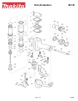
AG125
Brand: Makita Pages: 3
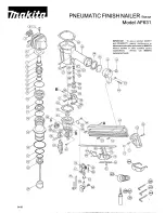
AF631
Brand: Makita Pages: 2
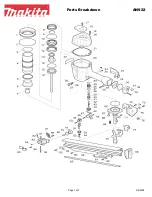
AN922
Brand: Makita Pages: 3
AF503
Brand: Makita Pages: 32
AN621
Brand: Makita Pages: 3
AN942
Brand: Makita Pages: 7
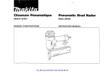
DBN500
Brand: Makita Pages: 24
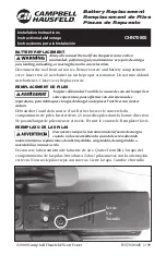
CHN71500
Brand: Campbell Hausfeld Pages: 2
CHN70600
Brand: Campbell Hausfeld Pages: 2
IronForce IFN2190
Brand: Campbell Hausfeld Pages: 12
CHN70800
Brand: Campbell Hausfeld Pages: 1

RH Series
Brand: D'Orly Pages: 11
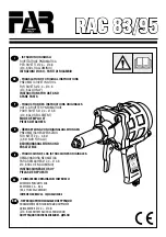
Rac 83
Brand: FAR Pages: 32

PET 25 A1
Brand: Parkside Pages: 44
PDRS 6.3 A1
Brand: Parkside Pages: 71
PAT 20-Li A1
Brand: Parkside Pages: 89

PSN90
Brand: Paslode Pages: 15
PHET 15 A1
Brand: Parkside Pages: 35


