background image

Dash

® 

Port 2

Docking Station

Service Manual

2000966-138

Revision A 

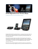
Summary of Contents for Dash Port 2

Page 1: ...Dash Port 2 Docking Station Service Manual 2000966 138 RevisionA ...

Page 2: ...below are GE Medical Systems Information Technologies trademarks used in this document All other trademarks contained herein are the property of their respective owners DASH SAM and UNITY NETWORK are trademarks of GE Medical Systems Information Technologies registered in the United States Patent and Trademark Office GE Medical Systems Information Technologies 2003 All rights reserved ...

Page 3: ...r 1 4 General 1 4 Hazard Definitions 1 5 Equipment Symbols 1 6 Service Requirements 1 7 Equipment Identification 1 8 2 Equipment Overview 2 1 Equipment Description 2 3 Basic Components 2 3 Optional Components 2 5 Theory of Operation 2 6 Overview 2 6 Block Diagram 2 7 Controls and Indicators 2 8 Controls 2 8 Indicators 2 8 Equipment Compatibility 2 9 Compatible Dash Monitors 2 9 Compatible Auxiliar...

Page 4: ...nstall Checkout 3 14 4 Maintenance 4 1 Maintenance Schedule 4 3 Manufacturer Recommendations 4 3 Visual Inspection 4 4 Cleaning 4 5 Cleaning Precautions 4 5 Exterior Cleaning 4 5 Electrical Safety Tests 4 6 General 4 6 Recommendations 4 6 Power Outlet Test 4 7 Ground Earth Integrity 4 8 Ground Earth Wire Leakage Current Tests 4 10 Enclosure Leakage Current Test 4 11 Test Completion 4 12 Checkout P...

Page 5: ...embly PN 2013500 002 Rev A 6 5 Connector Assembly PN 2013500 003 Rev A 6 6 PCB Board PN 2013500 004 Rev A 6 7 Hardware and Fasteners 6 8 Interconnection Diagram 6 9 Exploded View PN 2004740 002 Revision A 6 10 Parts ListPN 2004740 002 Revision A 6 12 Other Components 6 14 Displays 6 14 GCX Mounts 6 14 Video Cables and Video Cable Extenders 6 14 Disassembly Assembly of FRUs 6 16 Guidelines for Disa...

Page 6: ... Docking Station Revision A 2000966 138 Appendix B Remote Display B 1 Purchaser s Responsibility B 3 Medical Grade Displays B 3 Computer Grade Displays B 3 Required Specifications for Computer Flat Panel Displays B 4 ...

Page 7: ...Revision A Dash Port 2 Docking Station 1 1 2000966 138 1 Introduction ...

Page 8: ...1 2 Dash Port 2 Docking Station Revision A 2000966 138 For your notes ...

Page 9: ...sembly level Use it as a guide for maintenance and electrical repairs considered field repairable Where necessary the manual identifies additional sources of relevant information and technical assistance See the operation instructions for the instructions necessary to operate the equipment safely in accordance with its function and intended use Manual Conventions The Dash Port 2 docking station wi...

Page 10: ...arts and accessories used must meet the requirements of the applicable IEC 601 series safety standards and or the system configuration must meet the requirements of the IEC 60601 1 1 medical electrical systems standard Periodically and whenever the integrity of the device is in doubt test all functions The use of ACCESSORY equipment not complying with the equivalent safety requirements of this equ...

Page 11: ... as a source of potential injury to a person Term Definition DANGER Indicates an imminent hazard which if not avoided will result in death or serious injury WARNING Indicates a potential hazard or unsafe practice which if not avoided could result in death or serious injury CAUTION Indicates a potential hazard or unsafe practice which if not avoided could result in minor personal injury or product ...

Page 12: ...onsult accompanying documents equipotential lock unlock communication indicator front panel icon Ethernet back panel icon video out Alternating Current AC Medical Equipment With respect to electric shock fire and mechanical hazards only in accordance with UL 2601 1 and CAN CSA C22 2 NO 601 1 001A 002A 003A 030A 4P41 ...

Page 13: ...nder warranty voids that warranty It is the user s responsibility to report the need for service to GE or to one of their authorized agents Failure on the part of the responsible individual hospital or institution using this equipment to implement a satisfactory maintenance schedule may cause undue equipment failure and possible health hazards Regular maintenance irrespective of usage is essential...

Page 14: ...logies device has a unique serial number for identification A sample of the information found on a serial number label is shown below Description A product code1 1 The product code for the Dash Port 2 docking station is AAA B year manufactured C fiscal week manufactured D production sequence number E manufacturing site F miscellaneous characteristic A B C D E F ...

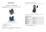
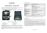
Page 15: ...Revision A Dash Port 2 Docking Station 2 1 2000966 138 2 Equipment Overview ...

Page 16: ...2 2 Dash Port 2 Docking Station Revision A 2000966 138 For your notes ...

Page 17: ...auxiliary devices Front View Name Description A Security lever Slide left to lock the monitor onto the docking station then slide right to unlock the monitor B AC mains power indicator Illuminates green when AC power is applied to the docking station C Communication indicator green LED A steady green color indicates the docking station has established communication with the monitor amber LED A fla...

Page 18: ... display the Dash monitor screen items in a larger size See Appendix B Remote Display for required and recommended remote display specifications C AUX 1 connector Connect to a compatible auxiliary device that is supported by the Dash monitor and by the docking station See Compatible Auxiliary Devices on page 2 10 D AUX 2 connector E AC power connector Insert AC power cable See Power Requirements o...

Page 19: ...y A Dash 3000 4000 monitor is required The Dash 3000 4000 monitor must use software version 5 0 or later The remote display must be compatible with the docking station See Appendix B Remote Display for required and recommended remote display specifications The maximum video cable length between the docking station and the remote display is 45 72 meters 150 feet See Other Components on page 6 14 fo...

Page 20: ... Dash Port Interface Isolation PCB to provide a means to quickly and reliably attach detach the Dash family of transport monitors The docking station can be installed at a bedside location in a health care facility and in an intra hospital patient transport The docking station is designed to provide electrical and mechanical connection of AC power and communication devices to the Dash family monit...

Page 21: ...itor Dash Port 2 FLEX CKT COMM INTFC Connector Dash Expansion Connector Autoport Isolation Circuitry RJ45 Autoport 1 Peripheral Autoport Multi Port HD DB 15 Video Connector SDRAM 64 Mb Flash 32 Mb Video DEC MPC823e LCD Controller SCC3 SCC2 SMC2 Address Data and Control bus ENET Isolation Circuitry RJ45 Ethernet System Clock 25 17500 MHz Peripheral ENET Port Peripheral ASYNC Port Debug Port Develop...

Page 22: ...the full right position it will unlock the monitor Releasing the lever at this point will allow the lever to return to the midpoint position and prevent unintentional detachment To remove the monitor you must hold the lever in the far right position while lifting the monitor off the docking station Indicators AC Power Indicator A green colored LED is used to indicate that the docking station is co...

Page 23: ...elow the communication links supported by a monitor are dependent upon the monitor s model and software version Monitor Model and Software Version Supported Communication Links AC Power Ethernet Network Auxiliary 1 Auxiliary 2 Remote Display Dash 2000 version 1 and 2 software Yes No No No No Dash 2000 version 3 or later software Yes Yes Yes No No Dash 3000 version 1 software Yes Yes No No No Dash ...

Page 24: ...Technologies Sales Representative for product availability Supported GE Auxiliary Devices The following GE devices are supported by the both the monitor and by the docking station s AUX connectors DT 7000 Transceiver Patient Data Management System RAC 2A module housing with one of the following modules inserted ICG module interface SAM module Remote alarm box Remote control Unity Network ID Suppor...

Page 25: ...Quantity Constraints DT 7000 Transceiver 1 Patient Data Management System 3 RAC 2A module housing 2 When two RAC 2A module housings are connected to the AUX connectors the monitor will monitor and display data received from one ICG module and one SAM module simultaneously As a result do NOT connect two ICG module interfaces or two Sam Modules to the monitor and docking station Remote Alarm Box 3 S...

Page 26: ...emote displays 15 inch medical grade flat panel color LCD display 18 inch medical grade flat panel color LCD display Off the shelf computer grade displays are also compatible See Appendix B Remote Display for the required and recommended remote display specifications 51 1 PATIENT RISK Do not connect a monochrome display to the Dash Port 2 docking station The visual alarm messages may not appear pr...

Page 27: ...Revision A Dash Port 2 Docking Station 3 1 2000966 138 3 Installation ...

Page 28: ...3 2 Dash Port 2 Docking Station Revision A 2000966 138 For your notes ...

Page 29: ...to parts of the system when it has been determined by qualified biomedical engineering personnel that there is no danger to the patient the operator or the environment as a result In those instances where there is any element of doubt concerning the safety of connected devices the user must contact the manufacturers concerned or other informed experts for proper use In all cases safe and proper op...

Page 30: ... Manual to change the voltage selector setting In U S A if the installation of this equipment will use 240V rather than 120V the source must be a center tapped 240V single phase circuit This equipment is suitable for connection to the public mains as defined in CISPR 11 Location Docking Station Choose a location which provides an unobstructed view of the monitor screen and easy access to the opera...

Page 31: ...the monitor from the mount could cause the mounting arm to unexpectedly spring upwards The docking station has a standard GCX mounting plate for quick mount dismount access The following are some of the GCX mounting devices available from GE Multi use pedestal style mount PN 2007059 001 M series wall arm with pivot PN 407349 009 Locking Variable Height Mount VHM arm PN 2014448 001 127 For addition...

Page 32: ... as a stand alone pedestal mount bolt on counter mount or slide in mount for use with anesthesia machine top mounted channel 2 Mount pn 2007059 001 includes triangular Pedestal base 30 5cm 12in Tilt Swivel head w 3 2cm 1 25in pipe 12 7cm 5in Mounting plate and combination Counter Mt Slide Plate Adapter Counter Mt Slide Plate Adapter 7 6 cm 3 0 in Multi Use Pedestal Style Mount 2007059 001 ...

Page 33: ...parately See note below Note Depending upon the style of the wall arm used existing box style or new M series selecting the correct RAC2A mount is important Existing arms use pn 404757 001 and new M series arms use either pn 404757 001 or pn 2004465 001 5 Maximum allowable supported weight 13 6 kilograms 30 pounds 40 6 cm 16 in 2004465 001 Optional RAC2A Mount See note 4 Optional RAC2A Mount See n...

Page 34: ...ing procedure is the same for the M Series and Locking VHM arm wall mounts 1 Slide the docking station onto the GCX mount until it bumps into the locking pin 2 Pull down and hold onto the locking pin and continue to slide the docking station onto the GCX mount Then let go of the locking pin 3 Verify the locking pin clicks into position to secure the docking station to the GCX mount 032A locking pi...

Page 35: ...ld NOT exceed 45 72 meters 150 feet See Other Components on page 6 14 for a list of video cables and video cable extenders 2 When connecting an auxiliary device see the documentation that was provided with the device and the Dash Patient Monitor Operator s Manual for cable and configuration requirements 005A auxiliary device 12 AC power remote display1 auxiliary device 22 Unity MC Network ...

Page 36: ...on and until you verify the monitor is properly secured to the docking station Position and Lock the Monitor 1 Verify the security lever starts in the unlock far right position 2 Position the front of the Dash monitor onto the front channel of the docking station 3 Hold onto the monitor and allow the weight of the monitor to descend firmly onto the docking station The security lever should move au...

Page 37: ...rify the green colored AC power indicator is illuminated on both the docking station and the monitor 3 Verify a green colored communication indicator is illuminated on the docking station1 1 Some Dash 2000 monitors do not support the docking station s Ethernet or auxiliary communication links See Compatible Dash Monitors on page 2 9 038A 1 3 2 2 ...

Page 38: ...ys may require a manual adjustment Automatic Adjustment 1 Power up the monitor and the remote display 2 From the monitor select MORE MENUS PATIENT DATA VITAL SIGNS 3 Verify the Vital Signs NRT displays correctly on the remote display a If the remote display image is good no manual adjustments are required b If the remote display image is very blurry or cut off complete a Manual Adjustment on page ...

Page 39: ... 3 Verify the Vital Signs NRT displays correctly on the remote display 4 If the Vital Signs NRT does NOT display correctly on the remote display complete the following tasks a Display the Vital Signs NRT on the monitor and on the remote display b Complete an auto adjust auto tune procedure as described in the documentation provided with the remote display 041A Bad Remote Display Image Blurry or Cu...

Page 40: ...14 Dash Port 2 Docking Station Revision A 2000966 138 Installation PM Install Checkout PM Install Checkout Complete the Electrical Safety Tests and Checkout Procedures identified in Chapter 4 Maintenance ...

Page 41: ...Revision A Dash Port 2 Docking Station 4 1 2000966 138 4 Maintenance ...

Page 42: ...4 2 Dash Port 2 Docking Station Revision A 2000966 138 For your notes ...

Page 43: ...ibility rests with the individuals hospitals or institutions utilizing the device To ensure the docking station is always functional when required qualified service personnel should perform the following regular maintenance Visual Inspection Perform a visual inspection upon receipt of the equipment every 12 months thereafter and prior to servicing the unit Cleaning Clean the unit upon receipt of t...

Page 44: ...eafter and each time the equipment is serviced Carefully inspect the equipment for physical damage Do not use the docking station if damage is determined Refer damaged equipment to qualified service personnel Inspect all external connections for loose connectors or frayed cables Have any damaged connectors or cables replaced by qualified service personnel Safety labels and inscription on the devic...

Page 45: ...o avoid damage to the equipment surfaces never use the following cleaning agents organic solvents ammonia based solutions acetone solution alcohol based cleaning agents Betadine solution a wax containing a cleaning substance or abrasive cleaning agents Exterior Cleaning Clean the exterior surfaces with a clean lint free cloth and one of the cleaning solutions listed in the table above Wring the ex...

Page 46: ...on follow the procedures provided in this manual as a guide during visits to the equipment site GE recommends that you perform electrical safety tests upon receipt of the device every twelve months thereafter and each time the main enclosure is disassembled or a circuit board is removed tested repaired or replaced Test Conditions Electrical safety tests may be performed under normal ambient condit...

Page 47: ...tlet to ensure correct results from leakage tests For international power outlets refer to the internal standards agencies of that particular country Use a digital multimeter to ensure the power outlet is wired properly If other than normal polarity and ground is indicated corrective action must be taken before proceeding The results of the following tests will be meaningless unless a properly wir...

Page 48: ...ctor or the protective earth pin in the Mains plug ground pin in power cord Refer to the US 120Vac power cord figure above 3 Set the DMM to the milliohm mΩ range 4 Connect the positive lead of the DMM to all exposed metal surfaces on the device under test If the metal surfaces are anodized or painted scrape off a small area in a inconspicuous place for the probe to make contact with the metal 5 Re...

Page 49: ...ailure in basic insulation 2 The voltage drop between the parts described is measured and the impedance determined from the current and voltage drop It shall not exceed the values indicated For equipment without a power supply cord the impedance between the protective earth terminal and any accessible metal part which is protectively earthed shall not exceed 0 1 ohms For equipment with a power sup...

Page 50: ... leakage indicated on DMM 127 If either reading is greater than the appropriate specification below the device under test fails Contact GE Medical Systems Information Technologies Technical Support 300 µA 0 3 volts on the DMM and the device under test is powered from 100 120 V 50 60 Hz 300 µA 0 3 volts on the DMM and the device under test is powered from a centered tapped 200 240 V 50 60 Hz single...

Page 51: ... 5 Read the current leakage indicated on DMM 127 If either reading is greater than the appropriate specification below the device under test fails Contact GE Medical Systems Information Technologies Technical Support 300 µA 0 3 volts on the DMM and the device under test is powered from 100 120 V 50 60 Hz 300 µA 0 3 volts on the DMM and the device under test is powered from a centered tapped 200 24...

Page 52: ... powered from 100 240 V 50 60 Hz the device under test fails Contact GE Medical Systems Information Technologies Technical Support 100 microamperes 0 1 volts on the DMM and the device under test is powered from 100 240 V 50 60 Hz Test Completion Disconnect all test equipment from the device Disconnect the device power cord plug from the leakage tester power receptacle Disconnect the leakage tester...

Page 53: ...mended test equipment adaptors and cables you need to successfully complete the checkout procedures The checkout procedures are written for the test equipment in the following table If you use test equipment other than those GE recommends you may need to slightly modify some test steps Patient Simulators and Cables ECG Test Marq I ECG Simulator no longer available for ordering MarqII KIT includes ...

Page 54: ...tation from AC power to turn the monitor off 4 Restore the batteries to the monitor and plug the docking station into AC power to turn the monitor on 5 Verify all the monitor s front panel indicators illuminate on power up 6 Verify both of the docking station s front panel indicators illuminate on power up 7 Verify the AC indicator on the monitor stays illuminated 127 If the AC LED stays on but th...

Page 55: ... it on and wait for all of the parameter boxes to display on the monitor 6 Select MORE MENUS VIEW OTHER PATIENTS SELECT ANOTHER CARE UNIT 7 Verify that you can see at least one care unit 8 Select a care unit 9 Select SELECT A BED TO VIEW 10 Select a bed 11 Verify that the patient window appears on the monitor s split screen Auxiliary Port Test Complete the remote control test to verify the docking...

Page 56: ... Test 1 Verify the docking station is connected to the remote display 2 Power up the monitor and the remote display 3 From the monitor select MORE MENUS PATIENT DATA VITAL SIGNS 4 Verify the Vital Signs NRT displays correctly on the remote display See Adjust the Remote Display Option Video Signal on page 3 12 ...

Page 57: ...Revision A Dash Port 2 Docking Station 4 17 2000966 138 Maintenance Checkout Procedures PM Repair Log Unit Serial Number Institution Name Date Maintenance Repair Technician ...

Page 58: ...4 18 Dash Port 2 Docking Station Revision A 2000966 138 Maintenance Checkout Procedures Unit Serial Number Institution Name Date Maintenance Repair Technician ...

Page 59: ...Revision A Dash Port 2 Docking Station 5 1 2000966 138 5 Troubleshooting ...

Page 60: ...5 2 Dash Port 2 Docking Station Revision A 2000966 138 For your notes ...

Page 61: ...matically adjust to the docking station s video output signal Other remote displays may require a manual adjustment to display the monitor data correctly See Adjust the Remote Display Option Video Signal on page 3 12 if the remote display image shows any of the following symptoms The image on the remote display appears to flicker Part of the image on the remote display cut off Area to Inspect Prob...

Page 62: ... of range have a qualified electrician repair the outlet The voltage measurements should be as follows 1 120 VAC 10 VAC between the line contact and neutral and between the line contact and ground 2 Less than 3 VAC between neutral and ground 240 VAC 50 60 Hz Use a digital voltmeter set to measure at least 300 VAC to check the voltages of the NEMA 6 20R AC wall outlet dedicated circuit recommended ...

Page 63: ... s security lever is in the far left position when a monitor is connected to the docking station See Mount the Dash Monitor on page 3 10 Problems and Solutions Table Problem Cause Solution The docking station s amber colored communication indicator IS flashing The monitor does not support the remote display and auxiliary 2 communication links Use a monitor that is fully compatible with the docking...

Page 64: ... lever pin and slide the security lever to the far left position 3 Verify the AC power communication mechanism extends out of the docking station s base and locks into position 4 If the AC power communication mechanism does NOT extend out of the docking station s base see The AC power communication mechanism does NOT extend out of the docking station s base on page 5 10 5 If the AC power communica...

Page 65: ...he docking station the monitor must use Dash 3000 4000 software version 5 0 or later See Compatible Dash Monitors on page 2 9 The auxiliary cable is damaged 1 Disconnect the auxiliary cable from the docking station 2 Connect the auxiliary cable to the monitor 3 If the monitor cannot communicate with the auxiliary device replace the auxiliary cable The auxiliary device may need to be configured to ...

Page 66: ...roblem The room s circuit breaker has been tripped Contact facility maintenance department to identify and repair the problem The electrical power cable to the docking station is defective 1 Verify the electrical power cable is defective by connecting a known good electrical power cable to the docking station 2 If the docking station s AC power indicator is now illuminated replace the defective po...

Page 67: ... communication mechanism does NOT extend out of the docking station s base on page 5 10 5 If the AC power communication mechanism extends out of the docking station s base then complete the following tasks a Verify the integrity of the J1 connection on the PCB b Verify AC power is available at J1 c Verify AC power is available at the Connector Assembly s AC connector d If AC power is available at ...

Page 68: ...ing properly 1 Separate the Top and Bottom Housings on page 6 17 2 Move the security lever to the far left position 3 Verify the top housing mechanisms move through their full range of motion e If a mechanism is defective Replace the Top Housing FRU on page 6 18 The locking lever pin or spring are either missing or not installed correctly See Join the Top and Bottom Housings on page 6 25 Problems ...

Page 69: ...isplayed 1 Allow the remote display to automatically adjust to the video signal See Automatic Adjustment on page 3 12 2 If the text and waveforms continue to appear broken up manually adjust the remote display s video signal See Manual Adjustment on page 3 13 No picture appears on the remote display and the following conditions apply The remote display s illuminated LED is flashing amber The docki...

Page 70: ...e docking station See Replace the Connector Assembly FRU or PCB FRU on page 6 19 c If a picture still does NOT appear on the remote display replace the monitor The security lever is already in the central position BEFORE the monitor has been placed on the docking station The locking mechanism may have been accidentally activated before the monitor was placed on the docking station 1 Remove the mon...

Page 71: ... docking station The Top Assembly FRU has failed 1 Remove the six screws from the bottom of the docking station to separate the top housing of the docking station from the bottom housing of the docking station 2 Use a bladed screw driver to manually release the docking station s clamps from the base of the monitor 3 If necessary contact Technical Support 4 Replace the Top Housing FRU on page 6 18 ...

Page 72: ...5 14 Dash Port 2 Docking Station Revision A 2000966 138 Troubleshooting Troubleshooting Procedures For your notes ...

Page 73: ...Revision A Dash Port 2 Docking Station 6 1 2000966 138 6 Part Lists Drawings and Replacement ...

Page 74: ...6 2 Dash Port 2 Docking Station Revision A 2000966 138 For your notes ...

Page 75: ...drawings in this chapter supply enough detail for you to order parts for the assemblies considered field serviceable If you require additional information or troubleshooting assistance contact Technical Support To order parts contact Service Parts at the address or telephone number listed on the How to Reach Us page found in the front of this manual ...

Page 76: ...laceable Units are available for this product See Top Assembly PN 2013500 002 Rev A on page 6 5 See Connector Assembly PN 2013500 003 Rev A on page 6 6 See PCB Board PN 2013500 004 Rev A on page 6 7 See Hardware and Fasteners on page 6 8 127 The hardware and fasteners are included with the top assembly connector assembly and the PCB FRUs 034A 037A 035A 037A 036A 037A 037A ...

Page 77: ...ON 1 3 DOOR CONNECTOR 1 6 ASSY LEVERS DOCKING STATION 1 9 LABEL DASH PORT 2 FRONT PANEL 0 20 SPACER ACETAL 25 LG 2 22 SCR MACH PNHD M4X6LG SST W THD LOCK 4 26 WASHER M3 PLAIN S S 2 27 SCR TAPPING TF M3 X 6 LG 2 50 PKG BAG CUSHION ZIP 15 X 15 STATIC SHLD 1 51 BOX MAILER 11 75L 11 00W 2 88H 1 52 LABEL CARTON FRU DASHPORT 2 1 Hardware FRU See Hardware and Fasteners on page 6 8 1 Label Kit Dash Port 2...

Page 78: ...laceable Units FRUs Connector Assembly PN 2013500 003 Rev A Find Number Item Description Qty 7 ASSY CONNECTOR DOCKING STATION 1 50 PKG BAG BUBBLE ZIP 8 X 12 ANTI STATIC 1 51 BOX MAILER 9 75L 2 88H 7 38W 1 52 LABEL CARTON FRU DASHPORT 2 1 Hardware FRU See Hardware and Fasteners on page 6 8 1 035A 037A ...

Page 79: ...RUs PCB Board PN 2013500 004 Rev A Find Number Item Description Qty 5 LED VERT LIGHT PIPE ASSY 235MM 1 11 PCB ACCESSORY INTERFACE DASH PORT 2 1 50 PKG BAG BUBBLE ZIP 6 X 10 ANTI STATIC 1 51 BOX MAILER 7 00L 6 00W 2 50H 1 52 LABEL CARTON FRU DASHPORT 2 1 Hardware FRU See Hardware and Fasteners on page 6 8 1 036A 037A ...

Page 80: ...ded with each FRU item 037A Find Number Item Description Qty 4 PIN LOCK LEVER 1 8 SPRING CPRSN 7 6 OD X 14 2 LG 1 10 SCR MACH PNHD M3X6LG SST W THD LOCK 5 16 PLUG MC EQUIPOTENTIAL 1 17 WASHER LOCK SERRATED F M 6 1 22 SCR MACH PNHD M4X6LG SST W THD LOCK 2 23 SCR MACH PNHD M4X10LG SST THD LOCK 4 28 SCR PH M4X 7X6 0LG SEMS 3 50 BAG ZIPLOCK CLR 2MIL POLY 5X7 1 52 LABEL CARTON FRU DASHPORT 2 1 ...

Page 81: ...Revision A Dash Port 2 Docking Station 6 9 2000966 138 Part Lists Drawings and Replacement Interconnection Diagram Interconnection Diagram ...

Page 82: ...6 10 Dash Port 2 Docking Station Revision A 2000966 138 Part Lists Drawings and Replacement Exploded View PN 2004740 002 Revision A Exploded View PN 2004740 002 Revision A Page 1 of 2 ...

Page 83: ...Revision A Dash Port 2 Docking Station 6 11 2000966 138 Part Lists Drawings and Replacement Exploded View PN 2004740 002 Revision A Page 2 of 2 ...

Page 84: ...TATION 1 8 SPRING CPRSN 7 6 OD X 14 2 LG 1 9 LABEL DASH PORT 2 FRONT PANEL 0 10 SCR MACH PNHD M3X6LG SST W THD LOCK 5 11 PCB ACCESSORY INTERFACE DASH PORT 2 A1 1 12 LABEL DASH PORT RATINGS 0 13 PACKAGING CORRUGATE SLEEVE DASHPORT 1 14 INSERT PACKAGING DOCKING STATION TOP 1 15 INSERT PACKAGING CONN PROTECTOR 1 16 PLUG MC EQUIPOTENTIAL 1 17 WASHER LOCK SERRATED F M 6 1 18 LABEL BLANK 2 6IN X 4IN 1 1...

Page 85: ...ing Station 6 13 2000966 138 Part Lists Drawings and Replacement Parts List PN 2004740 002 Revision A 28 SCR PH M4X 7X6 0LG SEMS 3 31 LED RT ANG GREEN LIGHT PIPE ASSY 292MM 0 Find Number Item Description Reference Designator Qty ...

Page 86: ... 4FT male to female video extender cable 415301 302 CA VID 75OHM HD15M HD15M 10FT male to female video extender cable 415301 303 CA VID 75OHM HD15M HD15M 25FT male to female video extender cable 415301 304 CA VID 75OHM HD15M HD15M 50FT male to female video extender cable 415301 305 CA VID 75OHM HD15M HD15M 75FT male to female video extender cable 415301 306 CA VID 75OHM HD15M HD15M 100FT male to f...

Page 87: ...male to female video extender cable 415301 407 Video Cable HD15M HD15F 150 male to female video extender cable 2002215 001 Analog Video Cable 6 male to male 15 pin D connector video replacement cable 2002215 002 Analog Video Cable 10 male to male 15 pin D connector video replacement cable 2002215 003 Analog Video Cable 15 male to male 15 pin D connector video replacement cable 2002215 004 Analog V...

Page 88: ...vided in the Field Replaceable Unit kit Some fasteners like the screws with a thread locking coating are NOT intended to be re used more than three times Tools Required A standard set of hand tools is required for disassembly and assembly Before Disassembly Before you disassemble the docking station you should ALWAYS remove AC power Hardware Assemblies When disassembling the docking station observ...

Page 89: ...e loosened screws are not self capturing and will fall out onto your work surface 2 Hold onto both housings and turn the unit over a clean work surface 3 Slide and hold the security lever in the far right position while separating the top and bottom housings 4 Continue to hold onto the security lever and gently let it slide back into its resting position 5 Remove the locking lever spring and pin 0...

Page 90: ...sts Drawings and Replacement Disassembly Assembly of FRUs Replace the Top Housing FRU 1 Separate the Top and Bottom Housings on page 6 17 2 Discard the defective top housing and install the replacement Top Housing FRU 3 Join the Top and Bottom Housings on page 6 25 ...

Page 91: ...D connector and gently remove the AC power indicator light pipe 3 Separate the Top and Bottom Housings on page 6 17 4 Stabilize the PCB LED connector and gently remove the communication indicator light pipe 5 If the light pipes are defective replace them a Push the light pipes out from the bottom assembly housing b Discard the defective light pipes 6 Use a 10 mm wrench or nut driver to remove the ...

Page 92: ...sts Drawings and Replacement Disassembly Assembly of FRUs 7 Remove the three connector assembly bracket screws from the bottom housing 8 Lift out the connector assembly 9 Unclip the two power connectors from the PCB 10 Remove the five PCB screws 025A 051A 056A 058A ...

Page 93: ...the PCB is defective follow your country requirements for disposal and install the PCB FRU b If the PCB is not defective reinstall the PCB into the connector assembly Connector Assembly a If the connector assembly is defective dispose of it and install the PCB FRU a If the connector assembly is not defective reinstall the connector assembly 13 Insert the PCB ribbon cable friction connector 055A 05...

Page 94: ...ll the five PCB screws b Insert the two power connectors 15 Position the replacement Connector Assembly FRU into the bottom housing 16 Start with the center screw and install the three connector assembly bracket screws 17 If the light pipes are to be replaced route the light pipes through the bottom housing s LED opening 058A step a b 051A 025A 1 3 2 049A ...

Page 95: ...e PCB light pipe connectors a Insert the light pipes through the molded guide holes b Be sure to route the AC power indicator light pipe BEHIND the plastic stand off 19 Gently push the light pipe lens into the lens opening until it is seated 20 Stabilize the PCB LED connector and gently insert the AC power indicator light pipe 053A b a a a a 052A 048A ...

Page 96: ...the communication indicator light pipe into the PCB connector 22 Replace the equipotential lug a Place the star washer onto the equipotential lug b Insert the lug into the threaded hole and tighten the lug 23 Join the Top and Bottom Housings on page 6 25 24 Insert the PCB ribbon cable friction connector 047A 054A 046A b a star washer 055A ...

Page 97: ...rity lever and place the top and bottom housing pieces together 4 Hold onto both housings and turn the unit over and install the six screws into the bottom housing 5 See After Reassembly on page 6 25 to identify the electrical safety tests and checkout procedures you must complete 029A Recommended Electrical Safety Tests and Checkout Procedures Replacement Procedure Electrical Safety Tests Checkou...

Page 98: ...6 26 Dash Port 2 Docking Station Revision A 2000966 138 Part Lists Drawings and Replacement Disassembly Assembly of FRUs For your notes ...

Page 99: ...2012659 002 A Appendix A Technical Specifications 127 Due to continual product innovation specifications are subject to change without notice The following specifications are accurate as of the date of this publication and pertain to the monitor ...

Page 100: ...A 2 Dash Port 2 Docking Station Revision A 2012659 002 For your notes ...

Page 101: ...pendix B Remote Display for additional specifications RJ45 connector RS232 hardware interface type autoport To connect M port devices to the AUX port use the M port to Auto port adapter PN 2001973 001 Operating Conditions operating temperature relative humidity non condensing altitude atmospheric pressure 0 to 40 C 32 to 104 F 5 to 95 at 40 C 104 F 610 to 4 570 m 2000 to 15 000 ft 425 to 817 mmHg ...

Page 102: ...A 4 Dash Port 2 Docking Station Revision A 2012659 002 Appendix A Technical Specifications Technical Specifications For your notes ...

Page 103: ...Revision A Dash Port 2 Docking Station B 1 2012659 002 B Appendix B Remote Display ...

Page 104: ...B 2 Dash Port 2 Docking Station Revision A 2012659 002 For your notes ...

Page 105: ...t the display manufacturer The GE warranty only applies to equipment purchased from GE Service repairs resulting from failures of equipment not purchased from GE are billable 127 An isolation transformer must be used with a computer grade display to meet UL and IEC specifications Medical Grade Displays The docking station with a medical grade display meets applicable UL and IEC specifications for ...

Page 106: ... are REQUIRED specifications Electrical Horizontal Sync Rate 31 47 KHz see note Sync Input TTL negative Vertical Refresh Rate 60 Hz see note Sync Input TTL negative Video Non composite 0 7Vp p analog RGB Polarity Black negative Resolution 640 x 480 Input Impedance 75 ohms 127 Multiscan displays indicate the sync rate and the refresh rate as ranges e g 20 KHz to 80 KHz rather than a single value To...

Page 107: ... ...

Page 108: ... 1 414 355 3790 European Representative GE Medical Systems Information Technologies GmbH Munzinger Str 3 5 D 79032 Freiburg Germany Tel 49 761 45 43 0 Fax 49 761 45 43 233 Asia Headquarters GE Medical Systems Information Technologies Asia 24th Floor Shanghai MAXDO Center 8 Xing Yi Road Hong Qiao Development Zone Shanghai 200336 P R China Tel 86 21 5208 2008 Fax 86 21 5208 2006 ...

Reviews: