

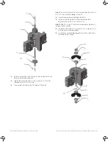
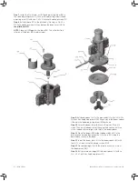
Summary of Contents for Becker HPP-5
Page 18: ... ...
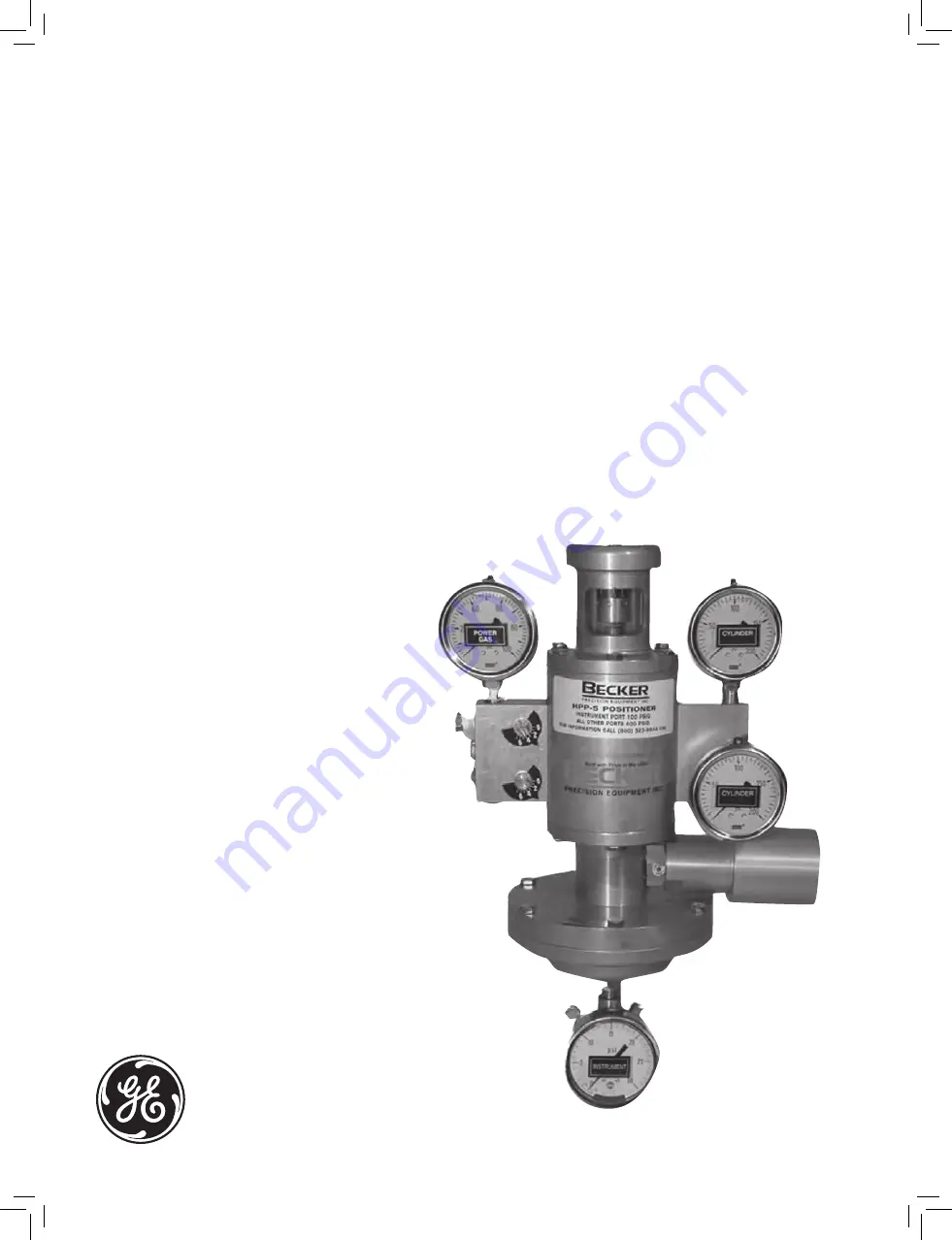
The GE Becker HPP-5 Installation and Maintenance Manual is a comprehensive guide that provides step-by-step instructions for optimum setup and care. This invaluable manual is available for free download from manualshive.com, ensuring easy access to vital information essential for efficient operation and maintenance of your GE Becker HPP-5 product.
Page 18: ... ...


