ATS1340
Door junction box
EN
FI
DE
IT
2006
GE
Security
B.V.
1056702
n
o
J1
J9
J6
J2
J3
J8
J12
FH1
FH2
J4
RL3
RL1
J15
J16
J13
J14
ATS1340
D4
D5
D+
D-
+12V
0V
CWG
CWG
0V
12/24V
OC OUT
SPARE
CW
G
CW
G
0V
+1
2V
D-
D+
0V
(+
)
+
OC
CW
G
CW
G
Zn+
1
Zn
EX
TE
RN
TA
M
PE
R
MA
G
N
S
W
.
ON
DO
OR
SW.
IN
D
O
O
R
LOCK
12
/2
4V
F
O
R
DO
OR LOCK
+ E
XIT
-B
U
TT
O
N
D+
D-
+12V
0V
OC DOOR REL
EXIT/B.LED
BUZ.
R/B LED
1
2
3
4
5
6
7
8
9
A
B
C
D
ATS1340
A
9 8
B
4
1
2
3
56
EN
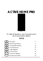
ATS1340
Door junction box
What does it do?
The ATS1340 is designed as a universal door junction box.
The module has an incoming and outgoing data bus / power connection
to achieve a proper stub connection for an Advisor MASTER bus reader.
Onboard relays are provided to connect a door lock and auxiliary outputs
(i.e. buzzer). For high-energy locks an external 12 V or 24 V power supply
must be connected.
Two onboard dual loop resistor inputs configurations are prepared to
connect a magnetic switch on the door and the switch in the door lock if
necessary. These connections can be easily hardwired to the nearest
DGP or panel zones.
The Advisor MASTER bus reader can be fully wired to the door junction
box and a request to the exit button easily can be connected as well. For
more details of the door application please see figure .
WARNING:
1.
Disconnect the mains power before opening the cabinet!
•
Disconnect AC mains plug from AC mains wall
socket, or
•
disconnect the mains with the dedicated circuit
breaker.
2.
Disconnect the battery (when applicable).
Description of ATS1340 and door application
See figure and figure .
Table 1. Connection description
Item Description
1 From
auxilary
output
2
12 V/24 V ext. power supply
3
Databus IN from panel or DGP
4
Databus OUT to RAS / DGP
5
Auxilary relay output (RL3)
6
Auxilary OC output
7 Shield
8
To Smart Card reader
9 RTE
button
10
Door lock relay output (RL1)
11 From
door
switches
12 From
external
tamper
13
To zone inputs
Mounting location
The ATS1340 PCB (see figure )
can be mounted in any Advisor MASTER
cabinet, which supports the size B board. Preferably the door junction box
must be mounted in close proximity to a door, which needs access
control and / or alarm facilities.
Mounting the unit
Mounting the ATS1340 door junction box on the wall or ceiling.
See figure .
1.
Remove the ATS1340 cover.
2. Hold the base of the ATS1340 against the mounting surface and
mark the mounting holes.
3.
Drill holes and insert screw anchors, if required.
All
rights
reserved.
09/2006
www.gesecurity.net