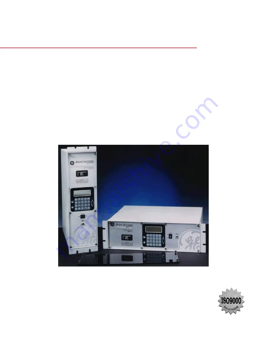
background image

ALPS

Advanced Line Protection™ System

Instruction Manual

Firmware Revision: V0004.04AA34 (Rev. A models)

Firmware Revision: 

V0005.02AA05 (Rev. B models)

Manual P/N: GEK-105555F

Copyright © 2002 GE Power Management

GE Power Management

215 Anderson Avenue, Markham, Ontario

Canada L6E 1B3

Tel: (905) 294-6222   Fax: (905) 294-8512

Internet: http://www.GEindustrial.com/pm

Note: All relays must be powered up at least once per year to avoid

deterioration of electrolytic capacitors and subsequent relay failure.

Manufactured under an

ISO9002 Registered system.

g

GE Power Management

Summary of Contents for ALPS

Page 1: ...t 2002 GE Power Management GE Power Management 215 Anderson Avenue Markham Ontario Canada L6E 1B3 Tel 905 294 6222 Fax 905 294 8512 Internet http www GEindustrial com pm Note All relays must be powered up at least once per year to avoid deterioration of electrolytic capacitors and subsequent relay failure Manufactured under an ISO9002 Registered system g GE Power Management ...

Page 2: ......

Page 3: ...ould further information be desired or should partic ular problems arise which are not covered sufficiently for the purchaser s purpose the matter should be referred to the General Electric Company To the extent required the products described herein meet applicable ANSI IEEE and NEMA standards but no such assurance is given with respect to local codes and ordinances because they vary greatly ...

Page 4: ......

Page 5: ...TION 1 16 1 5 5 FAULT REPORT 1 16 1 5 6 OSCILLOGRAPHY 1 16 1 5 7 PLAYBACK 1 17 1 5 8 SEQUENCE OF EVENTS 1 17 1 5 9 EQUIPMENT DUTY 1 17 1 5 10 SELECTABLE GROUPS OF SETTINGS 1 17 1 5 11 TIME SYNCHRONIZATION 1 18 1 5 12 TRIP BUS CHECK 1 18 1 5 13 TRIP CIRCUIT MONITOR 1 18 1 5 14 ALARMS 1 19 1 5 15 METERING 1 19 1 5 16 BREAKER CONTROL 1 19 1 6 COMMUNICATIONS 1 6 1 KEYPAD AND DISPLAY 1 20 1 6 2 SERIAL ...

Page 6: ... DESCRIPTION 2 1 2 2 GENERAL SETTINGS 2 2 1 CONFIGURATION 2 2 2 2 2 COMMUNICATIONS 2 4 2 2 3 OSCILLOGRAPHY 2 6 2 2 4 EQUIPMENT DUTY 2 6 2 2 5 PROGRAMMABLE INPUTS 2 8 2 3 PROTECTION SETTINGS 2 3 1 Z1DISTANCE 2 9 2 3 2 ZONE 2 ZONE 3 AND ZONE 4 DISTANCE FUNCTIONS 2 13 2 3 3 Z2DISTANCE 2 14 2 3 4 Z3DISTANCE 2 16 2 3 5 Z4DISTANCE 2 18 2 3 6 CURSUPVISN 2 22 2 3 7 OVERCURRNT 2 25 2 3 8 VOLTAGE 2 27 2 3 9...

Page 7: ...NSTRUCTIONS 4 2 4 1 7 SETTING CHANGES 4 3 4 1 8 ENTERING TEST MODE 4 4 4 1 9 USING COMMUNICATIONS OPTIONAL 4 4 4 2 GENERAL RELAY TESTS 4 2 1 T1 RELAY STATUS AND DISPLAY TESTING 4 7 4 2 2 DISPLAY AND KEYPAD TESTS 4 7 4 2 3 T2 DIGITAL OUTPUT TEST 4 8 4 2 4 T3 CONFIGURABLE INPUT AND OUTPUT TEST 4 9 4 2 5 T4 AC SYSTEM INPUT TEST 4 10 5 FUNCTIONAL TESTS FACTORY SETTINGS 5 1 TEST SUMMARY 5 1 1 DESCRIPTI...

Page 8: ...CKING SCHEMES 6 6 6 3 4 T7 GROUND DIRECTIONAL TRIP TEST IPT NT 6 6 6 3 5 T8 GROUND DIRECTIONAL BLOCK TEST IPB NB 6 7 6 4 BACKUP PROTECTION TESTS 6 4 1 T9 PHASE INSTANTANEOUS OVERCURRENT 50 6 8 6 4 2 T10 GROUND INSTANTANEOUS OVERCURRENT 50G 6 8 6 4 3 T11 GROUND TIME OVERCURRENT 51G 6 9 6 5 ZONE REACH TESTS 6 5 1 GENERAL CONSIDERATIONS 6 10 6 5 2 ZONE 1 4 PHASE TO GROUND CALCULATIONS 6 10 6 5 3 T12 ...

Page 9: ...ATION PASSWORDS 8 21 8 2 9 REQUEST STATION LINE ID 8 21 8 2 10 REQUEST ALPS MODEL VERSION 8 21 8 2 11 OSCILLOGRAPHY SNAPSHOT 8 22 8 3 ASCII INTERFACE 8 3 1 DESCRIPTION 8 23 8 3 2 RECOMMENDED REMOTE COMMUNICATIONS PACKAGE 8 23 8 4 REMOTE COMMUNICATION INTERFACE 8 4 1 HARDWARE SWITCHES 8 24 8 4 2 MODEM CONNECTIONS AND SETTINGS 8 24 8 4 3 PC MODEM 8 25 8 4 4 ALPS MODEM 8 25 8 4 5 NULL MODEM CONNECTIO...

Page 10: ...0 10 4 EDIT MENU 10 4 1 COPY 10 11 10 4 2 COPY TEXT ONLY 10 11 10 4 3 COPY MHO CIRCLE ONLY 10 11 10 5 VIEW MENU 10 5 1 DESCRIPTION 10 12 10 5 2 TOOLBAR 10 12 10 5 3 STATUS BAR 10 12 10 6 TOOLS MENU 10 6 1 DESCRIPTION 10 13 10 7 WINDOW MENU 10 7 1 DESCRIPTION 10 15 10 7 2 CASCADE 10 15 10 7 3 TILE 10 15 10 7 4 ARRANGE ICONS 10 15 10 7 5 VIEWING MULTIPLE TESTS 10 15 10 8 HELP MENU 10 8 1 CONTENTS 10...

Page 11: ...INT REPORT 11 16 11 7 LOGGING 11 7 1 SESSION LOG 11 17 11 7 2 TURN OFF 11 17 11 7 3 CURRENT SESSION LOG 11 17 11 7 4 OPEN SESSION LOG 11 17 11 7 5 ARCHIVAL 11 17 11 7 6 ARCHIVE 11 17 11 7 7 RETREIVE 11 18 12 ASCII COMMUNICATIONS 12 1 INTRODUCTION 12 1 1 DESCRIPTION 12 1 12 1 2 ASCII INTERFACE 12 1 13 XPRESSION BUILDER 13 1 INTRODUCTION 13 1 1 OVERVIEW 13 1 13 1 2 INSTALLATION 13 1 13 1 3 DESIGN CO...

Page 12: ... 00 DEVICE PROFILE DOCUMENT C 2 C 2 2 IMPLEMENTATION TABLE C 4 C 2 3 IMPLEMENTATION TABLE NOTES C 5 C 2 4 DEFAULT VARIATIONS C 5 C 3 POINT LISTS C 3 1 DESCRIPTION C 6 C 3 2 BINARY INPUT BINARY INPUT CHANGE C 6 C 3 3 BINARY OUTPUT CONTROL RELAY OUTPUT BLOCK C 11 C 3 4 BINARY COUNTER FROZEN COUNTER C 12 C 3 5 ANALOG INPUT ANALOG INPUT CHANGE C 13 C 3 6 ANALOG OUTPUT ANALOG OUTPUT BLOCK C 19 C 3 7 DA...

Page 13: ...ons on operating the keypad are found in Chapter 8 LOCAL USER INTERFACE GE Power Management contact information GE Power Management 215 Anderson Avenue Markham Ontario Canada L6E 1B3 Telephone Toll Free North America 800 547 8629 Europe 34 94 485 88 54 Other Areas 905 294 6222 Emergency 416 414 4941 Fax 905 201 2098 Email info pm indsys ge com Home Page www GEindustrial com pm 1 1 2 PASSWORDS FACT...

Page 14: ...LPS relay requires the use of passwords to obtain information from the relay to change Settings or to perform Actions The relay is shipped from the factory with the following communications passwords VIEW VIEW SETTINGS SETTING ACTIONS CONTROL MASTER MASTER The exclamation point following the letters is part of the factory password The factory passwords MUST be changed before the user can modify Se...

Page 15: ...cations without series capacitors C For Applications with series capacitors Battery Voltage 0 48V DC battery voltage 1 110 125 V DC battery voltage 2 220 250 V DC battery voltage Trip Outputs 1 SCR trip outputs contact channel interface 2 Contact trip outputs contact channel interface 3 SCR trip outputs 5V 20mA channel interface 4 Contact trip outputs 5V 20 mA channel interface Comm Ports 2 Front ...

Page 16: ...NS The measurement functions are listed in Table 1 2 ALPS MEASUREMENT FUNCTIONS on page 1 5 The Zone 1 distance functions provide secure high speed tripping for all fault types over most of the protected line The Zone 1 ground distance functions can be selected to be either ground variable Mho distance functions or ground reac tance distance functions The ALPS also offers ground quadrilateral dist...

Page 17: ...e functions 3 Variable Mho ground distance functions 3 Reactance ground distance functions with adaptive reach Mho supervision or 3 Quadrilateral ground distance functions Revision B relays only Zone 2 Pilot Zone 3 Variable Mho phase distance functions 3 Variable Mho ground distance functions and or Ground directional overcurrent functions consisting of IPT Ground Trip overcurrent NT Negative Sequ...

Page 18: ...quence component of X XM memory pre fault value of X Zx1 Zone x positive sequence reach setting ZxR POSSEQANG Zx0 Zone x zero sequence reach setting ZxR ZERSEQANG Note The magnitudes of Zx1 and Zx0 are identical these quantities differ in phase angle only K01 Zone 1 zero sequence compensation factor Z1K0 K0 zero sequence compensation factor a REACTANCE CHARACTERSTIC The reactance characteristic us...

Page 19: ...Z11 Phase C IC I0 Z11 K01 I0 Z10 VC IC2 Z11 I0 Z11 IC1F Z11 b RESTRICTED DIRECTIONAL CHARACTERISTIC The restricted directional characteristic for the ground quadrilateral requires a separate directional unit for each phase No settings are required for this characteristic The input signals to the comparator are Phase A IA ZD VA Phase B IB ZD VB Phase C IC ZD VC where ZD is the angle of maximum torq...

Page 20: ... operate and polarizing signals are 1 2 5 LINE PROTECTION SCHEMES The ALPS provides four zones of distance protection with overcurrent backup functions The ALPS is a highly flexible sys tem along with predefined protection schemes it also has the ability to be programmed by the user The custom program mability of the ALPS is discussed in the next section The ALPS pilot protection schemes are as fo...

Page 21: ...s and 8 latches 1 3 3 CONFIGURABLE INPUTS All of the contact converters Digital Inputs in the ALPS are user configurable However each ALPS relay is shipped with Default Contact Converter Assignments as shown below and on the default elementary diagrams on pages 1 49 to 1 52 Each configurable input can be assigned only one flag assigning more than one flag to a configurable input may cause malopera...

Page 22: ...SE A TRIPA 33 A5 THREE PHASE RECLOSE INITIATE RI 3P 37 A6 THREE PHASE RECLOSE INITIATE RI 3P 37 A7 RECLOSE CANCEL OUTPUT FROM SCHEME LOGIC CANCL 38 A8 to A12 UNASSIGNED KT1 KEY TRANSMITTER 1 CARRIER START 1 KEY1 39 KT2 KEY TRANSMITTER 2 CARRIER STOP 1 KEY2 40 KT3 KEY TRANSMITTER 1 CARRIER START 1 KEY1 39 KT4 KEY TRANSMITTER 2 CARRIER START 2 KEY2 40 C1 NON CRITICAL ALARM NCALM 52 C2 PT FUSE FAILUR...

Page 23: ...lt detector FD has operated or whether one or more phases of the protected line are de energized open When one or more phases of protected line are open PTFF is disabled Figure 1 3 POTENTIAL FUSE FAILURE LOGIC DIAGRAMS If AC potential is lost for any reason including a blown fuse or fuses and there is no disturbance on the power system that operates the fault detector the AND1 output causes timer ...

Page 24: ...t enough to pickup the All Phase Voltages High signal This is accomplished by routing Zone 2 phase distance or ground distance func tion outputs to AND401 The step distance backup timers are bypassed by the Line Pickup logic If the line is energized and no fault exists the all Phase Voltages High signal picks up and timer TL401 will begin timing 40 ms later the output of TL402 resets timer TL401 v...

Page 25: ... before the other end s operates The ROD function should not be consid ered as a replacement or substitute for pilot schemes Figure 1 6 REMOTE OPEN DETECTOR LOGIC ROD is a functional logic diagram of the ROD function The sequence of events that results in an ROD output is as follows 1 No charging current is detected prior to the fault logic 0 output from AND2 2 A fault is detected logic 1 output f...

Page 26: ...the NOT via OR202 since MT A B has not operated yet The bottom NOT input of AND202 is satisfied since it is assumed that no phase is open and the AND202 output energizes timer TL1 If the impedance stays between the MOB and MT characteristics for the pickup time of TL1 an OSB output results The OSB output is routed back to the top input of AND202 via OR202 to seal in the OSB output for as long as M...

Page 27: ...S X R OSBRXDiag CDR 50 30 ms INITIAL PICKUP TIME ADAPTIVE AFTER FIRST SLIP CYCLE TL1 OSB 202 202 ANY COORDINATING ZONE PHASE OR GROUND ANY MOB OSB3P VSD 50 MT A B MOB A B 201 30 ms INITIAL PICKUP TIME ADAPTIVE AFTER FIRST SLIP CYCLE TL1 OSB PHASE A OPEN 201 204 MT B C MOB B C 202 PHASE B OPEN 202 205 MT C A MOB C A 203 PHASE C OPEN 203 206 207 OSB1P VSD ALPS WITH SINGLE PHASE TRIPPING ALPS WITH TH...

Page 28: ...t events that are stored is selectable by the user A relay with standard memory option may be set for 2 4 8 or 12 fault reports A relay with extended memory option may be set for 6 12 24 or 36 fault reports Each fault report is associated with an oscillography data file See Section 8 2 3 REQUEST FAULT INFORMATION on page 8 17 for obtaining a fault report through the local user interface and Sectio...

Page 29: ...stem events operator actions and self test alarms The sequence of events can be accessed remotely via the front panel port PL 1 or PL 2 and a PC A full event list contained in Section 8 2 7 EVENT INFORMA TION on page 8 19 1 5 9 EQUIPMENT DUTY When the ALPS is applied with a single breaker it incorporates the ability to monitor the number of breaker operations and the breaker duty Alarm levels can ...

Page 30: ... and voltage at the relay at that instant A Trip Bus Check also occurs before a newly selected settings group is allowed to become the active settings group If Trip Bus Check finds a picked up trip function protection is turned off and a critical alarm is issued This check provides a degree of confidence in the new settings but it does not guarantee that one or more trip functions might not operat...

Page 31: ...nd may be programmed to a user assigned output contact The non critical alarm is de energized in normal con ditions The default inputs to the non critical alarm include the following conditions 1 Trip Circuit Alarm 2 Zone Flags On Alarm 3 Overcurrent Alarm 4 Unbalance Current Alarm Detector Additional inputs such as line overload alarm may be added by the user via Xpression Builder 1 5 15 METERING...

Page 32: ...ry map and DNP 3 0 protocol information are contained in Appendices B and C respectively 1 6 3 SCADA DIGITAL TO ANALOG DTA INTERFACE An internal DTA function standard on the ALPS provides the following An analog output proportional to the distance from the relay to the fault as calculated by the fault location algorithm Four contact outputs that provide fault type information The analog output is ...

Page 33: ...nd self tests that do not interfere with the foreground tasks use of serial and parallel ports and that do not inhibit interrupts to any processor If any background self test fails the test is repeated For a compo nent to be declared as failed the test must fail three consecutive times In the case of most critical failures the ALPS forces a reset to attempt to get the failed component working agai...

Page 34: ...ion of the Fault Detector If such a condition occurs and persists for 1 second the ALPS relay will issue a Non Critical Alarm and log a Continuous Monitor event These Continuous Monitor Alarm points are found in Table 2 10 INDEX NUMBERS SCHEME RECLOSER PRO GRAMMABLE LOGIC on page 2 52 The Index numbers used for the Continuous Monitor are as follows 48 Trip Circuit alarm 49 ZONE flags on alarm 50 O...

Page 35: ...NCE LOGIC DIAGRAM on page 1 27 is the logic diagram for the Step Distance scheme for the ALPS single phase and three phase models respectively Since this non pilot scheme overlays the other protection schemes in the ALPS it is in essence a part of all of them The Zone 1 distance functions are set to reach no greater than 90 of the positive sequence impedance of the protected line All of the ground...

Page 36: ...T SUPERVISION IT IB PHASE DISTANCE GROUND DISTANCE PHASE DISTANCE GROUND DISTANCE PHASE BACKUP 50P OSBALL C 0 C 0 D 0 D 0 TL4G TL4P TL3G TL3P 13 28 12 11 OSB 1 4 11 11 C 0 4 to 6 sec D 0 4 to 6 sec ZONE 4 OSB OSB ZONE 3 R E V E R S I B L E Z O N E 4 Z O N E 3 Z O N E 1 O V E R R E A C H I N G Z O N E Z O N E 2 13 OSB STP_DST3 VSD OUT OF STEP BLOCKING LOGIC OSB Settings 1601 to 1607 CNFTRP CONFIGUR...

Page 37: ...s with a POTT1 scheme This is necessary since the Zone 1 functions at only one end of the three terminal line may respond for an internal fault For a three terminal PUTT application do not use 52 b contact keying of the transmitter Because the two receivers are ORed together a continuous trip signal sent from the open end when only one end is open results in over tripping for external faults withi...

Page 38: ...E PHASE DISTANCE GROUND DISTANCE PHASE BACKUP OSBALL FFB Setting 714 C 0 C 0 D 0 D 0 TL4G TL4P TL3G TL3P 13 28 12 11 OSB 1 4 25 11 11 C 0 4 to 6 sec D 0 4 to 6 sec ZONE 4 OSB OSB ZONE 3 REVERSIBLE ZONE 4 ZONE 3 ZONE 1 OVERREACHING ZONE ZONE 2 13 OSB OSB Setting 1202 KEY1 KEY2 Setting 205 PUTT3 VSD OUT OF STEP BLOCKING LOGIC OSB Settings 1601 to 1607 CNFTRP CONFIGURABLE TRIP BUS 8 RECLOSE CANCEL RE...

Page 39: ... Timer TL4 in conjunction with timer TL1 prevents a possible misopera tion when a fault current reversal occurs as a result of sequential clearing of a fault on a parallel line Note that tripping is supervised by the Fault Detector at AND7 thus confirming that tripping occurs only after a fault on the power system The above description assumes a two terminal line When a POTT1 scheme is applied on ...

Page 40: ... CURRENT SUPERVISION PHASE DISTANCE GROUND DISTANCE PHASE DISTANCE GROUND DISTANCE PHASE BACKUP 50P OSBALL FFB Setting 714 C 0 C 0 D 0 D 0 TL4G TL4P TL3G TL3P 13 28 12 11 OSB 1 4 25 11 11 C 0 4 6 sec D 0 4 6 sec Zone 4 OSB OSB Zone 3 R E V E R S I B L E Z O N E 4 Z O N E 3 Z O N E 1 O V E R R E A C H I N G Z O N E Z O N E 2 13 OSB OSB Setting 1202 KEY1 KEY2 Setting 205 POTT1 VSD OUT OF STEP BLOCKI...

Page 41: ...0 D 0 D 0 TL4G TL4P TL3G TL3P 13 503 20 28 12 BLOCK ZONE 1 Setting 110 1 103 2 25 11 C 0 4 to 6 sec D 0 4 to 6 sec Zone 4 Zone 3 REVERSIBLE ZONE 4 ZONE 3 ZONE 1 OVERREACHING ZONE ZONE 2 13 Protection Setting 1202 KEY1 KEY2 Protection Setting 205 POTT2 VSD CNFTRP CONFIGURABLE TRIP BUS 8 RECLOSE CANCEL RECLOSE INITIATE BLOCK RECLOSING Settings 801 810 9 9 TRIP TRIP BUS 44 7 7 6 103 BLOCK ZONE 1 Sett...

Page 42: ...locking input applied to comparator AND407 via CC1 and NOT3 The sequence of operations is similar for an internal ground fault Ground distance ground directional overcurrent or both functions acting in parallel may be selected for ground fault protection Ground distance and ground directional overcurrent each have separate trip and block functions as well as separate transient blocking circuits Th...

Page 43: ...hat turns the transmitter OFF permitting the remote end to trip FAULT DETECTOR LINE PICKUP CANCL RI 3 4 F 1 50 TL1 F 50 25 X B 0 3 407 3 8 301 508 302 209 22 213 208 CARRIER START CARRIER STOP OSB Zone 2 TL24 2 2 RCVRS 1 RCVR 21 CC RCVR1 CC RCVR2 TL2G B 0 REF REF B 0 2 3 0 SEC CC STCR PHASE DISTANCE GROUND DISTANCE GROUND DIRECTIONAL OVER CURRENT TRIP BLOCK REMOTE OPEN PHASE DISTANCE GROUND DISTAN...

Page 44: ...GATIVE BATTERY 1 7 13 9 38 14 2 6 4 17 3 18 5 10 37 8 B21 B5 KT1 NOTE NC CONTACTS ARE ALSO AVAILABLE FOR CARRIER START STOP D18 D2 CC1 RECEIVED CARRIER ALPS ALPS SET FOR BLOCKING SCHEME PICKSCHEME 4 BLOCKING CS28A INTERCONNECT DIAGRAM FOR PILOT BLOCKING SCHEME USING CS28A CARRIER SET AND ALPS RELAY SYSTEM 14 13 2 39 3 40 U13 U12 U11 U10 B6 B23 KT2 START STOP START STOP REDUCED POWER SUPERVISORY SH...

Page 45: ... weak in feed terminal At the strong in feed termi nal s the transmitter is keyed to the trip frequency At the weak in feed terminal the blocking functions have not operated and the receiver produces an output when it receives the trip frequency This output is applied to timer TL11 and AND102 via OR101 AND102 produces an output until timer TL11 times out 80 ms after receipt of the trip signal An A...

Page 46: ...c D 0 1 10 sec Zone 4 Zone 3 R E V E R S I B L E Z O N E 4 Z O N E 3 Z O N E 1 O V E R R E A C H I N G ZONE ZONE 2 13 Setting 1202 Setting 205 CNFTRP CONFIGURABLE TRIP TRIP PERMISSION 37 35 35 103 BLOCK ZONE 1 Setting 110 2 RCVRS 1 RCVR 101 G 8 505 WI 405 TL16 G 8 80 80 102 TL11 CC RCVR1 404 OSB 205 TL26 F 0 F 0 50 REF Setting 1205 305 V1 DETECTOR 3 WI OUT OF STEP BLOCKING LOGIC OSB Settings 1601 ...

Page 47: ...ized for each fault The Trip Output logic for the ALPS is shown in below for all logic scheme except the Hybrid the logic for the Hybrid scheme is shown in Figure 1 20 SINGLE PHASE TRIPPING LOGIC HYBRID SCHEME on page 1 40 Figure 1 19 SINGLE PHASE TRIPPING LOGIC EXCEPT FOR HYBRID SCHEME NOTE FAULTED PHASE SELECTION LOGIC MULTI PHASE PHASE A PHASE C PHASE B OPEN POLE LOGIC C C EXTERNAL 3 POLE TRIP ...

Page 48: ...auxiliary contacts 52 b are not required for the relay to function correctly The Open Pole logic detects when any pole is open when only one pole is open and when all three poles are open FAULTED PHASE SELECTION LOGIC MULTI PHASE PHASE A PHASE C PHASE B OPEN POLE LOGIC CC EXTERNAL 3 POLE TRIP ENABLE 3 POLE TRIP ENABLE FLAG from internal recloser 3 POLE TRIP MODE FLAG Setting 1203 FAULT DETECTOR IT...

Page 49: ...e steady state level of I2 and I0 The Potential Transformer Fuse Failure Detection function is indicated as FFB on the logic diagrams For a Hybrid scheme the weak infeed logic is modified as shown in Figure 1 8 OSB LOGIC DIAGRAMS on page 1 15 and described above The operation of the Out of Step Blocking logic is modified as explained below If the ground directional overcurrent func tions are used ...

Page 50: ...of Fig A 1 will result in the tripping of all three phases of both line at Station R and proper single pole tripping at Station S The operation of the relays at Station R is due to the fact that they must rely on the local phase selection to determine the fault type and which phase or phases to trip The solution to the problem is to use the fault type information from both the local and remote end...

Page 51: ...s The phase identified channel logic scheme will use the information in the received signal as well as the undervoltage units If there is a local determination of the fault type the previous table will be used to determine which phases to trip if there is no local fault type determination then the undervoltage functions will be used as in the existing ALPS Hybrid scheme d REPEAT ECHO KEYING If no ...

Page 52: ...ed phase determination algorithm has been supplemented by undervoltage units for Weak Infeed trips The phase identified channel logic scheme will use the information in the received signal as well as the undervoltage units If there is a local determination of the fault type the previous table will be used to determine which phases to trip If there is no local fault type determination then the unde...

Page 53: ...TER MIDDLE INNER However by Protection Setting 1702 NUMBRCHAR the MIDDLE characteristic can be bypassed thereby using only the OUTER and INNER characteris tics for out of step detection The decision whether to use two or three characteristics depends largely on the maximum slip frequency expected during a swing condition Three characteristics are preferred if the slip frequency is low enough to pe...

Page 54: ...d input from OR61 since NOT61 has no input If the swing impedance remains between the OUTER and MIDDLE char acteristics for the pickup setting of TLOS1 TLOS1 operates seals in one input of AND61 When a fault occurs the OUTER and MIDDLE characteristics operate almost simultaneously and the MIDDLE blocks AND61 through NOT61 thus preventing TLOS1 from operating 2 The swing now enters the MIDDLE chara...

Page 55: ...has passed through the OUTER characteristic for the second time When the OUTER resets the second input of AND65 is supplied by NOT63 AND65 through OR65 picks up the out of step tripping relay OST This output lasts for 50 milliseconds three cycles at 60 Hz after the OUTER resets which is the dropout time of TLOS1 1 10 4 TWO CHARACTERISTIC OPERATION Operation with two characteristics instead of thre...

Page 56: ...e due to capacitance charging These functions provide the following advantages A local measurement of the balanced voltage A remote measurement of the voltage at the far end of the line which can detect 1 High voltage due to an open line and trip the energized end This is important since with high voltage more corona may exist on the line and inhibit the proper reception of a carrier transfer trip...

Page 57: ...requires a 1PRI input thus indicating that single pole trip ping was initiated Each subsequent reclose if used requires a 3PRI signal Following the initial single pole reclose a three pole trip enable signal will be issued so that if a fault is closed into the relay system s will initiate three pole trip ping of the breaker regardless of the fault type This three pole trip enable signal is issued ...

Page 58: ...r requires breaker b auxiliary switches to determine whether the breaker is in the open or closed position Because all ALPS inputs are programmable the correct number of contact converter s must be programmed for use as the breaker b switch inputs In three pole tripping schemes only one b switch input is required therefore only one con tact converter need be programmed for that input In single pol...

Page 59: ...Assignment can be made through ALPS Link Xpression Builder or the keyboard The following outputs are provided a CLOSE The close output controls reclosing of the breaker The dwell time setting Protection Setting 1814 DWELLTIME controls the time that the output contacts remain closed following a close command from the recloser b THREE POLE TRIP ENABLE This output is enabled whenever a reclose cycle ...

Page 60: ... the minimum voltage that must be present before the synchronism check functions are allowed to operate Protection Setting 1819 CLOSEANG set ting establishes the angle that the BUS and LINE voltages must be within before reclosing will be permitted In addition the slip frequency between the BUS and LINE voltages must be less than Protection Setting 1820 SLIPFREQ and both criteria must be satisfied...

Page 61: ...ne Protection System 1 49 1 PRODUCT DESCRIPTION 1 13 ELEMENTARY DIAGRAMS 1 1 13 ELEMENTARY DIAGRAMS 1 13 1 ELEMENTARY DIAGRAMS Figure 1 27 ELEMENTARY DIAGRAM WITH DEFAULT I O SINGLE PHASE TRIPPING ETR3P 52B_1B 52B_1C 52B_2A 52B_2B 52B_2C ...

Page 62: ...1 50 ALPS Advanced Line Protection System GE Power Management 1 13 ELEMENTARY DIAGRAMS 1 PRODUCT DESCRIPTION 1 Figure 1 28 ELEMENTARY DIAGRAM WITH DEFAULT I O THREE PHASE TRIPPING ...

Page 63: ...GE Power Management ALPS Advanced Line Protection System 1 51 1 PRODUCT DESCRIPTION 1 13 ELEMENTARY DIAGRAMS 1 Figure 1 29 ELEMENTARY DIAGRAM SINGLE PHASE TRIPPING 0145D8389 R08 ...

Page 64: ...1 52 ALPS Advanced Line Protection System GE Power Management 1 13 ELEMENTARY DIAGRAMS 1 PRODUCT DESCRIPTION 1 Figure 1 30 ELEMENTARY DIAGRAM THREE PHASE TRIPPING ...

Page 65: ...application All of the settings used in the ALPS are listed in Table 2 11 PROTECTION SETTINGS GUIDE on page 2 57 and Table 2 12 GENERAL SETTINGS GUIDE on page 2 64 These tables show setting ranges for both 5 A and 1 A rated systems Note that each specific setting in a subgroup has a distinctly assigned number in addition to a unique mnemonic These identification numbers can be used to facilitate e...

Page 66: ...ontacts from one breaker or two breakers are used to key the transmitter with the breaker s open 106 NUM_TC Number of Trip Circuits The number of trip outputs is dependent on whether the three phase or single phase tripping model is used Assignment of the trip outputs is made via the NUM_TC setting and is directly coupled to the NUM_BKR setting With the Single Phase Tripping model six outputs T1 t...

Page 67: ... to T4 for Three Phase Tripping models T1 to T6 for Single Phase Tripping models can be monitored regardless of whether or not they are used in a trip circuit For single phase tripping models the setting format for NUM_MON is abcdef where any position can be a zero 0 or a one 1 as shown below For three phase tripping models the setting format for NUM_MON is abcd where any position can be a zero 0 ...

Page 68: ...mal or 0000 to 1111 binary where the least significant digit represents SYSIN1 and the most significant digit repre sents SYSIN4 This value must be entered in decimal format The System Inputs can be incorporated into the relay logic with Xpression Builder allowing for greater control of the overall logic They can be treated like any digital input or flag For example System Inputs can provide super...

Page 69: ...ity and stop bits must match those set for the serial port of the remote PC Normally 1 stop bit is selected However certain modems or other communications hardware might dictate using 2 stop bits ALPS Link can set the baud rate parity and stop bits 204 PROTOCOL1 Communication Port No 1 Protocol Two settings are possible 1 GE MODEM Use this setting to communicate with the ALPS system via the ALPS L...

Page 70: ...e fault cycles SPLITREC is set as a percentage with a range of 0 to 100 and splits the record so that the end of the record is equal to the SPLITREC percentage and the beginning of the record is equal to 100 SPLITREC For example assume that NUMFAULTS is set to 4 and PREFAULT is set to 4 This means that the record will capture 4 cycles of pre fault data and 32 cycles of fault data The ALPS samples ...

Page 71: ...e set over the range of 0 to 999 9M with a step of 0 1K If the accumulated duty to that point in time is known enter that value otherwise enter an estimated value or use the default value of zero 0 406 IXTPHASEC Accumulated Duty Breaker Phase C IXTPHASEC can be set over the range of 0 to 999 9M with a step of 0 1K If the accumulated duty to that point in time is known enter that value otherwise en...

Page 72: ...09 CC9 Contact Converter 9 510 CC10 Contact Converter 10 511 CC11 Contact Converter 11 512 CC12 Contact Converter 12 Single Phase Tripping models only Use any of the 32 signals given in Table 2 9 on page 2 51 to define the function of these contact converters 501 CC1 Contact Converter 1 502 CC2 Contact Converter 2 503 CC3 Contact Converter 3 504 CC4 Contact Converter 4 505 CC5 Contact Converter 5 ...

Page 73: ...ACH WHEN USED WITH CVTS 103 Z1PLEVDET Zone 1 Phase Level Detector Setting Series Capacitor Model Only The distance functions are measured by comparing the phase relationship of an operate signal I Z V to a polarizing sig nal V where Z is the set reach of the function and I and V are the current and voltage seen by the function While this measurement alone is sufficient to provide secure and depend...

Page 74: ... taken into consideration Consider the forward fault at location F4 in Figure 2 3 POWER SYSTEM ONE LINE DIAGRAM WITH SERIES CAPACITORS above 1 Capacitors C3 and C4 need only be considered if line side potential is used 2 If bus side potential is used then capacitors C2 C3 and C4 must be taken into consideration Capacitor C4 should be treated as follows when determining the level detector setting 1...

Page 75: ...ster than that of the Reac tance or Quadrilateral function A very short line is one where the positive sequence source impedance equivalent source impedance behind the relay location divided by the positive sequence impedance of the protected line is greater than 5 Note that the value of 5 is a suggested boundary value not an absolute cutoff and that a reactance function can be selected for a long...

Page 76: ...ay location is essentially in phase with the total fault current for a single line to ground fault at the remote end of the line or if the fault current at the relay location is more lagging than the total fault current for a single line to ground fault at the remote end of the line On a non homogeneous system where the fault current at the relay location is more leading than the total fault curre...

Page 77: ...en the angles B and A shown in the figure above A circular Mho characteristic B 90 should be used when possible However for larger load flows smaller load impedances and for longer reaches it may be necessary to resort to a lenticular characteristic B 90 to remain within the allowable limit Lenticular settings greater than 120 should never be used Similarly the characteristic angle should never be...

Page 78: ...reach of the Zone 2 functions is set to 125 of line impedance then the operating time for remote faults would fall in the area of the upturn of the operating time characteristic and tripping will be affected accordingly On the other hand if the reach of the Zone 2 functions is set to 300 of the line or greater then the operating time for any line fault would fall along the flat part of the time ch...

Page 79: ...d in a ground directional overcurrent scheme GDOC it is also possible to use both the mho ground distance function and the ground directional overcurrent pilot schemes simulta neously MHOGDOC When Z2GRDCHAR is set to MHO2GDOC the IPT and IPB functions are modified to include a negative sequence current operating quantity in addition to the zero sequence quantity used with the GDOC and MHOG DOC set...

Page 80: ... delay If Z2TIMERS is set to NO then this setting is irrelevant and can be ignored 210 Z2G_TIME Z2 Ground Timer Revision B models only Z2G_TIME can be set over the range of 0 1 to 3 0 seconds and establishes the time delay that the Zone 2 phase functions can be picked up before tripping is initiated If the Zone 2 phase distance functions are set to provide traditional Zone 2 pro tection then set Z...

Page 81: ...et to see a multiphase fault at the end of the longest adjoining line section out of the remote bus considering such factors as arc resistance and underreach caused by intermediate fault current sources Z3GRDREACH should never be set so large as to 1 Exceed the maximum allowable reach MR or 2 To cause the Zone 3 functions to lose selectivity with the third zone ground distance functions on the sho...

Page 82: ...accuracy it is recommended that the resistive reach is not greater than 10 times the Ground Distance Reach Protec tion Setting 305 Z3GRDREACH for this zone 2 3 5 Z4DISTANCE The settings to be used on the Zone 4 distance functions in the ALPS system depend on the application and the scheme selected Both the phase and ground distance functions can be set to look in the reverse direction relative to ...

Page 83: ...in these schemes therefore set Z4PHASE YES Step Distance and POTT1 Schemes If the Zone 4 phase distance functions are to be used to provide time delayed backup protection then set Z4PHASE YES otherwise set Z4PHASE NO 402 Z4PHREACH Z4 Phase Distance Reach Blocking Hybrid and POTT2 Schemes In a blocking scheme the Zone 4 functions key the transmitter to send a blocking signal to the remote terminal ...

Page 84: ...etting Z2PCHARANGR of the Zone 2 functions at the remote terminal of the line that is Z4PCHARANG Z2PCHARANGR 10 Step Distance and POTT1 Schemes This setting determines the characteristic shape and consequently the area of resistance coverage provided by the Zone 4 phase distance functions Z4PCHARANG can be set to 80 to 120 in 5 steps A 90 setting is recommended values lower than 90 should not be u...

Page 85: ...kup protection They can provide a fourth zone of protection in a straight step distance scheme or they can be reversed in direction to provide the so called reversed third zone of protection The Zone 4 ground distance functions should be set with a reach commensurate to the application considering under reach caused by intermediate fault current sources Z4GRDREACH should never be set so large as t...

Page 86: ...ide coverage for resistive ground faults This setting should be a balance between desired fault resistance coverage and load encroachment It should be calculated as 0 8 if tent characteristics are used or less 0 6 to 0 7 if tent characteristics are not used of the positive sequence resistance seen by the relay under maximum load conditions and unity power factor Also to maintain zone accuracy it i...

Page 87: ...pping and blocking functions to provide increased security for any current unbalance that may occur during load flow or external fault conditions IPT and IPB must be set so as to provide proper coordination This is done by setting the IPB function more sensitively than the IPT function The following settings are proposed IPB_PICKUP minimum IPT_PICKUP 1 3 x IPB_PICKUPR Ioc where IPB_PICKUPR setting...

Page 88: ... voltage at a point some distance down the transmission line In the system with series capacitors and with line side potential as shown in Figure 2 11 NT NB FUNCTIONS on page 2 24 the effect of the capacitor is to cause the voltage to reverse as shown This will lead to incorrect directional sensing unless something is done to overcome the reversal The offset in this case provides a compensating vo...

Page 89: ... of the programmable outputs that may already have been selected for alarm duty 2 3 7 OVERCURRNT 601 50 Phase Instantaneous Overcurrent The 50 function can be used in many applications to provide high speed direct tripping for heavy close in faults To use the phase instantaneous overcurrent trip function set 50 YES otherwise set 50 NO See Protection Settings 602 and 603 for further discussion on u...

Page 90: ...st case external fault at either end of the line If 50G is controlled by the negative sequence directional functions then it must be set not to operate for the worst case external fault at the remote end of the line In general directional control should be used when the operating current for a fault behind the relay location is much greater than the operating current for a fault at the remote end ...

Page 91: ...5 51GTIMDIAL Ground Time Overcurrent Time Dial 51GTIMDIAL selects the 51G time dial setting 51GTIMDIAL can be set from 0 5 to 10 0 The pickup and time dial settings should be selected to provide coordination with similar functions in adjacent line sections 616 DEFTIMDELY Definite Time Delay When the 51G function is selected to have a definite time characteristic DEFTIMDELY determines the associate...

Page 92: ...eous Positive V1OVER Pickup V1OVINSTPU establishes the pickup setting of the instantaneous V1OVER function and can be set from 1 0 to 1 4 per unit volts based on the RATEDVOLTS setting If V1OVER is selected make a V1OVINSTPU setting that is suitable to the par ticular application 707 V1OVTIMPU Time Positive Sequence Overvoltage Pickup V1OVTIMPU establishes the pickup setting of the time delayed V1...

Page 93: ...If AC potential is lost for any reason including a blown fuse or fuses and there is no disturbance on the power system so that the fault detector has not operated AND1 produces an output that times out TL1 and produces a FUSEFAIL output via OR2 The output of OR2 is routed to AND2 to seal in the FUSEFAIL output based on the output of V1 so that FUSEFAIL output is maintained as long as the potential...

Page 94: ...tput of TL1 resets timer TL2 via the fast reset input AND1 and AND2 have the lower inputs removed at that time to take Line Pickup out of service If the line is energized and a fault exists current detector I1 or one of the Zone 2 distance functions will operate and AND1 and or AND2 will produce an output If BYPASSTL3 YES then the bottom input of AND3 is connected to and AND3 immediately produces ...

Page 95: ...stance scheme ROD tripping is beneficial for any unbalanced internal fault not detected by Zone 1 In a Blocking scheme ROD tripping is beneficial where system conditions are such that the fault current redistribu tion following breaker opening at one end is normally required before the other end s operates The ROD function should not be considered as a replacement or substitute for a pilot scheme ...

Page 96: ...nsists of two overcurrent units Level 1 and Level 2 with independent time delays Level 1 is intended to be used with the lower pickup and longer time delay Level 2 is intended to be used with the higher pickup and shorter time delay The pickup and time delay settings should be based on short time and emergency loading situations for the protected line 1101 LINEOVERLD Select Line Overload Protectio...

Page 97: ... 1 YES with this selection the Weak Infeed Tripping logic is enabled 2 NO with this selection the Weak Infeed Tripping logic is disabled but the Channel Repeat Echo logic remains in service A Voltage Fault Detector VFD is used with the Current Fault Detector FD in the Hybrid scheme The weak sides produce little or no fault current at the weak terminal and the current values may not be sufficient t...

Page 98: ...ore the main contacts of the breaker close The outputs of the timers are ANDed together when two breakers are used The switch shown below in Figure 2 13 TL5PICKUP TL6PICKUP REPRESENTATION is not a physical switch but rather a logical representation that is digitally controlled by General Setting 105 NUM_BKR as described in Section 2 2 1 CONFIGURATION on page 2 2 Figure 2 13 TL5PICKUP TL6PICKUP REP...

Page 99: ...hat can occur for faults near capacitors on series compensated lines and 3 transients that can occur for external fault clearing The following settings are proposed 1 Uncompensated Lines TL24DRPOUT 30 ms 2 Series Compensated Lines or Lines Adjacent to a Series Compensated Line TL24DRPOUT 125 ms 1310 TL25DRPOUT Distance Blocking Timer Step Distance and POTT1 Schemes Timer TL25 is not used in these ...

Page 100: ... P is the channel propagation time from the remote terminal to the local terminal 2 3 16 LINE INFO 1401 POSSEQANG Positive Sequence Impedance Angle POSSEQANG is common to all of the distance functions and establishes the positive sequence angle of maximum reach Set POSSEQANG to a value that is equal to or just larger than the angle of the positive sequence impedance of the pro tected line 1402 ZER...

Page 101: ...nts can be made from the keypad or by using Xpression Builder The DTA provides either a nominal 0 to 1 mA DC output or a nominal 0 to 5 V DC output The choice of output ranges is made by a switch located on the Processor Board When the fault location is calculated to be 100 of the line length the DTA output is either 0 8 mA DC or 4 0 V DC The DTA output goes to full scale either 1 mA DC or 5 V DC ...

Page 102: ...BCHARANG setting and determines the shape of the MOB characteristic Angle B should be set so the time for the fastest swing to traverse from angle B to angle A is not less than 30 milliseconds In addition the A and B angle settings must be selected so that the dif ference between angles B and C is never less than 20 Note that angle C is determined as a function of the minimum load impedance Zload ...

Page 103: ... to the slip frequency of the power system during an out of step condition Figure 2 15 OST CHARACTERISTIC The following settings must be made refer to above and 2 16 OST REACH CHARACTERISTIC It will most likely be nec essary to run load flow and system swing studies to determine the settings that must be made in any given application The example used below is provided only for use as a guide in de...

Page 104: ... swings Two factors are used in deter mining the outer and inner settings 1 the maximum load flow across the line which determines the minimum load impedance seen by the relay 2 the maximum swing angle that the power system can tolerate and beyond which the system cannot recover that is the system becomes unstable The OUTER characteristic angle setting angle A in Figure 2 16 OST REACH CHARACTERIST...

Page 105: ...2PU must be set less than the time that it takes for the fastest swing to travel from the outer to the middle characteristic The pickup time of TLOS3 establishes the final step in the out of step process and determines the time that the swing must remain inside of the inner characteristic before the final decision is made to produce an out of step trip It provides added security to the logic A min...

Page 106: ...ration the three pole trip enable signal will be set at all times This mode of operation requires four independent timers which hereafter will be referred to as 3PDELAY1 3PDELAY2 3PDELAY3 and 3PDELAY4 Protection Settings 1809 to 1812 3 1POLE 3POLE This mode of operation combines modes 1 and 2 above If a 1PRI input is first applied to the recloser then the program by the 1POLE setting will be follo...

Page 107: ...tablishes the delay to be used for the third three pole reclose attempt The delay time can be set over a range of 0 1 to 300 0 seconds Select a setting suitable for the application 1812 3PDELAY4 Three Pole Fourth Reclose Delay 3PDELAY4 establishes the delay to be used for the fourth three pole reclose attempt The delay time can be set over a range of 0 1 to 300 0 seconds Select a setting suitable ...

Page 108: ...ency for which the synchronism check function will allow the recloser to produce an output to close the breaker provided the closing angle requirement is met The SLIPFREQ setting has a range of 0 1 to 5 0 Hz Select a slip frequency suitable to the application 1821 BUSLINE Bus or Line Voltage BUSLINE can be set to BUS or LINE and identifies the source of the three phase voltage bus or line used to ...

Page 109: ... can be set over a range of 0 1 to 130 0 volts 1833 VBUSDEAD Dead Bus Voltage VBUSDEAD establishes the voltage at which the bus voltage must be less than before the functions requiring dead bus supervision are allowed to operate The voltage level can be set over a range of 0 1 to 130 0 V 1834 VLINELIVE Live Line Voltage VLINELIVE establishes the level which the line voltage must be greater than be...

Page 110: ...LPS Link will be reflected in the configurable logic file while any settings changed through the configurable logic will be reflected in the settings file If other than the default setting is to be used change the configurable logic or select an index number reflecting the function by which the contact is to be driven The following contact output assignments are recommended when the phase identifi...

Page 111: ...ONFOSC Trigger Oscillography The CONFOSC setting allows oscillography data capture to be initiated by the operation of selected signals within the ALPS logic or via external input through a contact converter Regardless of the setting of CONFOSC oscillography data capture will always occur when the ALPS issues a trip output Care should be taken to ensure that the signals chosen if one of the select...

Page 112: ...anagement 2 4 INVERSE CURVES 2 CALCULATION OF SETTINGS 2 2 4 INVERSE CURVES Figure 2 18 INVERSE CURVE 0 01 0 1 1 10 100 0 1 1 10 100 MULTIPLES OF PICKUP 10 9 8 7 6 5 4 3 2 1 0 5 TIME DIAL TIME SECONDS 2 1 97 0 M TD RESET t 0228 0 1 0103 0 02 0 M TD PU t ...

Page 113: ...ection System 2 49 2 CALCULATION OF SETTINGS 2 4 INVERSE CURVES 2 Figure 2 19 VERY INVERSE CURVE 0 01 0 1 1 10 100 0 1 1 10 100 MULTIPLES OF PICKUP 10 9 8 7 6 5 4 3 2 1 0 5 TIME DIAL TIME seconds 0982 0 1 922 3 2 M TD PU t 2 1 32 4 M TD RESET t ...

Page 114: ...Power Management 2 4 INVERSE CURVES 2 CALCULATION OF SETTINGS 2 Figure 2 20 EXTREMELY INVERSE CURVE 0 01 0 1 1 10 100 0 1 1 10 100 MULTIPLES OF PICKUP 10 9 8 7 6 5 4 3 2 1 0 5 TIME seconds TIME DIAL 2 1 82 5 M TD RESET t 02434 0 1 64 5 2 M TD PU t ...

Page 115: ...15 External Reclose Initiate 3 Pole EXRI3P 16 External Reclose Inhibit EXRINH 16 External Reclose Inhibit EXRINH 17 External Reclose Cancel EXRCNL 17 External Reclose Cancel EXRCNL 18 Reclose Reset RCLRST 18 Reclose Reset RCLRST 19 External Phase 3 Reclose CLOS3P 19 Spare 20 External Contact Input to Reset ALPS Trip Target Display RESET 20 Spare 21 Spare 21 Spare 22 External Contact Input to Disab...

Page 116: ...Current Detector Alarm Output UNBAL 51 Unbalanced Current Detector Alarm Output UNBAL 52 Non Critical Alarm Output NCALM 52 Non Critical Alarm Output NCALM 53 Spare 53 Key 3 54 Spare 54 Key 4 55 Spare 55 Spare 56 MANUAL OPEN BRK1 MNOPN1 56 MANUAL OPEN BRK1 MNOPN1 57 MANUAL OPEN BRK2 MNOPN2 57 MANUAL OPEN BRK2 MNOPN2 58 MANUAL CLOSE BRK1 MNCLS1 58 MANUAL CLOSE BRK1 MNCLS1 59 MANUAL CLOSE BRK2 MNCLS...

Page 117: ...ny Z3 Ground Distance Function Z3GRD 96 Any Z4 Ground Distance Function Z4GRD 96 Any Z4 Ground Distance Function Z4GRD 97 Phase A Open AOPEN 97 Spare 98 Phase B Open BOPEN 98 Spare 99 Phase C Open COPEN 99 Spare 100 All Phases Open 3OPEN 100 All Phases Open 3OPEN 101 Any Phases Open ANYOPN 101 Any Phases Open ANYOPN 102 1 Pole Open 1OPEN 102 Spare 103 Any Phase Undervoltage ANYUVT 103 Any Phase Un...

Page 118: ...se BKRCLS 146 Breaker Close BKRCLS 147 Trip Circuit 1 Voltage Monitor Status T1TC 147 Trip Circuit 1 Voltage Monitor Status T1TC 148 Trip Circuit 2 Voltage Monitor Status T2TC 148 Trip Circuit 2 Voltage Monitor Status T2TC 149 Trip Circuit 3 Voltage Monitor Status T3TC 149 Trip Circuit 3 Voltage Monitor Status T3TC 150 Trip Circuit 4 Voltage Monitor Status T4TC 150 Trip Circuit 4 Voltage Monitor S...

Page 119: ...ble Logic Gate 29 Output G29 189 Programmable Logic Gate 29 Output G29 190 Programmable Logic Gate 30 Output G30 190 Programmable Logic Gate 30 Output G30 191 Programmable Logic Gate 31 Output G31 191 Programmable Logic Gate 31 Output G31 192 Programmable Logic Gate 32 Output G32 192 Programmable Logic Gate 32 Output G32 193 Programmable Logic Gate 33 Output G33 193 Programmable Logic Gate 33 Outp...

Page 120: ...nter 5 CNTR5 245 Programmable Logic Counter 5 CNTR5 246 Programmable Logic Counter 6 CNTR6 246 Programmable Logic Counter 6 CNTR6 247 Programmable Logic Counter 7 CNTR7 247 Programmable Logic Counter 7 CNTR7 248 Programmable Logic Counter 8 CNTR8 248 Programmable Logic Counter 8 CNTR8 249 Programmable Logic LATCH 1 LATCH1 249 Programmable Logic LATCH 1 LATCH1 250 Programmable Logic LATCH 2 LATCH2 ...

Page 121: ...01 to 50 0 ohms step 0 01 0 05 to 250 0 ohms step 0 05 9 00Ω at 5A 45 0Ω at 1A 203 Z2PCHARANG Z2 Phase Characteristic Angle 90 to 120 step 5 90 deg 204 Z2GROUND Z2 Ground Distance NO YES YES 205 Z2GRDCHAR Z2 Ground Characteristic MHO GDOC MHOGDOC MHO2GDOC QUAD MHO 206 Z2GRDREACH Z2 Ground Reach 0 01 to 50 0 ohms step 0 01 0 05 to 250 0 ohms step 0 05 9 00Ω at 5A 45 0Ω at 1A 207 Z2GCHARANG Z2 Groun...

Page 122: ...amps step 0 01 0 10 to 1 0 amps step 0 01 0 75 A at 5A 0 15 A at 1A 504 IPB_PICKUP GDOC Block Current 0 25 to 3 75 amps step 0 01 0 05 to 0 75 amps step 0 01 0 25 A at 5A 0 05 A at 1A 505 IPBKFACTOR IPB I1 Restraint 0 0 0 066 0 066 506 NT_OFFSET NT NB Offset 0 0 to 20 0 ohms step 0 01 0 0 to 100 ohms step 0 01 0 05Ω at 5A 0 25Ω at 1A 507 UNBALALARM Unbalanced Current Alarm NO YES YES OVERCURRNT 60...

Page 123: ...el Only NO YES NO 710 V1COMPRCH Compensated Positive Sequence Overvoltage Impedance Overvoltage Model Only 0 01 to 50 0 ohms step 0 01 0 05 to 250 0 ohms step 0 05 6 0Ω at 5A 30 0Ω at 1A 711 V1COMPINPU INST Compensated Positive Sequence OV Pickup Overvoltage Model Only 0 0 to 1 4 p u volts step 0 01 1 4 p u V 712 V1COMPTDPU TOV Compensated Positive Sequence OV Pickup Overvoltage Model Only 0 0 to ...

Page 124: ...5 msec 1302 TL4PICKUP POTT Coord Timer PU 0 to 50 msec step 1 0 msec 1303 TL4DROPOUT POTT Coord Timer DO 0 to 50 msec step 1 0 msec 1304 TL5PICKUP BKR1 b sw Coord Timer PU 0 to 200 msec step 1 50 msec 1305 TL5DROPOUT BKR1 b sw Coord Timer DO 0 to 200 msec step 1 50 msec 1306 TL6PICKUP BKR2 b sw Coord Timer PU 0 to 200 msec step 1 50 msec 1307 TL6DROPOUT BKR2 b sw Coord Timer DO 0 to 200 msec step ...

Page 125: ...LOS1DO Coordinating Timer 1 Dropout 1 to 100 msec step 1 40 msec 1711 TLOS2PU Coordinating Timer 2 Pickup 1 to 100 msec step 1 40 msec 1712 TLOS3PU Coordinating Timer 3 Pickup 1 to 100 msec step 1 40 msec 1713 TLOS4PU Coordinating Timer 4 Pickup 1 to 100 msec step 1 40 msec RECLOSER 1801 RECLMODE Select Reclosing Option OFF NONE INTERNAL EXTERNAL BOTH OFF 1802 RECTYPE Set Reclosing Type 1POLE 3POL...

Page 126: ...30 volts step 0 1 50 V 1835 VLINEDEAD Dead Line Voltage 0 1 to 130 volts step 0 1 50 V 1836 LBUSDLINE Live Bus Dead Line NO YES NO 1837 DBUSLLINE Dead Bus Live Line NO YES NO 1838 DBUSDLINE Dead Bus Dead Line NO YES NO 1839 DELTAV Voltage Difference 0 1 to 30 volts step 0 1 10 V 1840 DELTAVBLK Block Synch Check by DELTAV NO YES NO NONCRIT_AL 1901 NCAIN1 Non Critical Alarm Input 1 These 8 inputs ar...

Page 127: ...ep 1 2017 A11 A11 Contact configurable 0 to 256 step 1 2018 A12 A12 Contact configurable 0 to 256 step 1 2019 C1 C1 Contact configurable 0 to 256 step 1 52 2020 C2 C2 Contact configurable 0 to 256 step 1 115 2021 KT1 KT1 Contact configurable 0 to 256 step 1 39 2022 KT2 KT2 Contact configurable 0 to 256 step 1 40 2023 KT3 KT3 Contact configurable 0 to 256 step 1 39 2024 KT4 KT4 Contact configurable...

Page 128: ...MPORT2 Communications Port 2 Settings Interface i Baud Rate xx Parity y Stop Bits z format ixxyz i 0 RS232 1 RS485 xx 03 12 24 48 96 y 0 none 1 odd 2 even z 1 2 09601 203 COMPORT3 Communications Port 3 Settings Interface i Baud Rate xx Parity y Stop bits z format ixxyz i 0 RS232 1 RS485 xx 03 12 24 48 96 y 0 none 1 odd 2 even z 1 2 09601 204 PROTOCOL1 Communications Port 1 Protocol GE MODEM ASCII ...

Page 129: ...s for Phase C 0 to 9999 1 0 INPUTS 501 CC1 Contact Converter 1 0 to 32 1 12 502 CC2 Contact Converter 2 0 to 32 1 13 503 CC3 Contact Converter 3 0 to 32 1 10 504 CC4 Contact Converter 4 0 to 32 1 11 505 CC5 Contact Converter 5 0 to 32 1 7 506 CC6 Contact Converter 6 0 to 32 1 507 CC7 Contact Converter 7 0 to 32 1 1 508 CC8 Contact Converter 8 0 to 32 2 4 509 CC9 Contact Converter 9 0 to 32 1 3 510...

Page 130: ...E 201 Z2PHASE Z2 Phase Distance NO YES 202 Z2PHREACH Z2 Phase Reach 0 01 to 50 0 ohms step 0 01 0 05 to 250 0 ohms step 0 05 203 Z2PCHARANG Z2 Phase Characteristic Angle 90 to 120 step 5 204 Z2GROUND Z2 Ground Distance NO YES 205 Z2GRDCHAR Z2 Ground Characteristic MHO GDOC MHOGDOC MHO2GDOC QUAD 206 Z2GRDREACH Z2 Ground Reach 0 01 to 50 0 ohms step 0 01 0 05 to 250 0 ohms step 0 05 207 Z2GCHARANG Z...

Page 131: ...s step 0 01 0 04 to 0 8 amps step 0 01 503 IPT_PICKUP GDOC Trip Current 0 50 to 5 0 amps step 0 01 0 10 to 1 0 amps step 0 01 504 IPB_PICKUP GDOC Block Current 0 25 to 3 75 amps step 0 01 0 05 to 0 75 amps step 0 01 505 IPBKFACTOR IPB I1 Restraint 0 0 0 066 506 NT_OFFSET NT NB Offset 0 0 to 20 0 ohms step 0 01 0 0 to 100 ohms step 0 01 507 UNBALALARM Unbalanced Current Alarm NO YES OVERCURRNT 601 ...

Page 132: ... V1COMP Compensated Positive Sequence Overvoltage Overvoltage Model Only NO YES 710 V1COMPRCH Compensated Positive Sequence Overvoltage Impedance Overvoltage Model Only 0 01 to 50 0 ohms step 0 01 0 05 to 250 0 ohms step 0 05 711 V1COMPINPU INST Compensated Positive Sequence OV Pickup Overvoltage Model Only 0 0 to 1 4 p u volts step 0 01 712 V1COMPTDPU TOV Compensated Positive Sequence OV Pickup O...

Page 133: ...MTIMERS 1301 TL1PICKUP Trip Integrator 1 to 200 msec step 1 1302 TL4PICKUP POTT Coord Timer PU 0 to 50 msec step 1 1303 TL4DROPOUT POTT Coord Timer DO 0 to 50 msec step 1 1304 TL5PICKUP BKR1 b sw Coord Timer PU 0 to 200 msec step 1 1305 TL5DROPOUT BKR1 b sw Coord Timer DO 0 to 200 msec step 1 1306 TL6PICKUP BKR2 b sw Coord Timer PU 0 to 200 msec step 1 1307 TL6DROPOUT BKR2 b sw Coord Timer DO 0 to...

Page 134: ... Coordinating Timer 1 Pickup 1 to 100 msec step 1 1710 TLOS1DO Coordinating Timer 1 Dropout 1 to 100 msec step 1 1711 TLOS2PU Coordinating Timer 2 Pickup 1 to 100 msec step 1 1712 TLOS3PU Coordinating Timer 3 Pickup 1 to 100 msec step 1 1713 TLOS4PU Coordinating Timer 4 Pickup 1 to 100 msec step 1 RECLOSER 1801 RECLMODE Select Reclosing Option OFF NONE INTERNAL EXTERNAL BOTH 1802 RECTYPE Set Reclo...

Page 135: ...D Dead Bus Voltage 0 1 to 130 volts step 0 1 1834 VLINELIVE Live Line Voltage 0 1 to 130 volts step 0 1 1835 VLINEDEAD Dead Line Voltage 0 1 to 130 volts step 0 1 1836 LBUSDLINE Live Bus Dead Line NO YES 1837 DBUSLLINE Dead Bus Live Line NO YES 1838 DBUSDLINE Dead Bus Dead Line NO YES 1839 DELTAV Voltage Difference 0 1 to 30 volts step 0 1 1840 DELTAVBLK Block Synch Check by DELTAV NO YES NONCRIT_...

Page 136: ...16 A10 A10 Contact configurable 0 to 256 step 1 2017 A11 A11 Contact configurable 0 to 256 step 1 2018 A12 A12 Contact configurable 0 to 256 step 1 2019 C1 C1 Contact configurable 0 to 256 step 1 2020 C2 C2 Contact configurable 0 to 256 step 1 2021 KT1 KT1 Contact configurable 0 to 256 step 1 2022 KT2 KT2 Contact configurable 0 to 256 step 1 2023 KT3 KT3 Contact configurable 0 to 256 step 1 2024 K...

Page 137: ...Interface i Baud Rate xx Parity y Stop Bits z format ixxyz i 0 RS232 1 RS485 xx 03 12 24 48 96 19 y 0 none 1 odd 2 even z 1 2 203 COMPORT3 Communications Port 3 Settings Interface i Baud Rate xx Parity y Stop bits z format ixxyz i 0 RS232 1 RS485 xx 03 12 24 48 96 19 y 0 none 1 odd 2 even z 1 2 204 PROTOCOL1 Communications Port 1 Protocol GE MODEM ASCII N A 205 PROTOCOL2 Communications Port 2 Prot...

Page 138: ...TS 501 CC1 Contact Converter 1 0 to 32 1 502 CC2 Contact Converter 2 0 to 32 1 503 CC3 Contact Converter 3 0 to 32 1 504 CC4 Contact Converter 4 0 to 32 1 505 CC5 Contact Converter 5 0 to 32 1 506 CC6 Contact Converter 6 0 to 32 1 507 CC7 Contact Converter 7 0 to 32 1 508 CC8 Contact Converter 8 0 to 32 509 CC9 Contact Converter 9 0 to 32 1 510 CC10 Contact Converter 10 0 to 32 1 511 CC11 Contact ...

Page 139: ...arget Reset Metering button is accessible via a hole in the front cover place by restraining screws on the front of the module trays The rear of the case supports terminal blocks for external connections to the relay The printed circuit board modules are mounted horizontally inside the case and connected via a bus card behind the front panel The boards also have rear edge connectors that electrica...

Page 140: ...CC12 A6 CRIT ALARM A6 PL3 PL2A PL2B A7 A7 A8 A8 P S ALARM I V 8 0 3 N 6 9 CLR ENT 1 Y 4 7 NOT Advanced Line Protection System T1 TERMINAL BLOCK C current and voltage inputs COMMUNICATION RS232 serial data port for local computer access TERMINAL BLOCK A 4 or 6 configurable trip contacts 8 configurable alarm contacts TERMINAL BLOCK B 0 or 4 configurable alarm contacts 4 high speed configurable conta...

Page 141: ...cuit boards via the Bus Card connected on the front side of the circuit boards The magnetics module is connected via a card edge connector to the bottom circuit board input board The current block contacts are rated to handle current transformer CT secondary currents Figure 3 3 CIRCUIT BOARD LOCATIONS 3 1 3 IDENTIFICATION The ALPS system model number label is located on the front cover The termina...

Page 142: ...the interconnections between the system modules Figure 3 4 ALPS SYSTEM BLOCK DIAGRAM SCADA INTERFACE DIGITAL INPUTS CONTACT CONVERTERS IRIG B TIME SYNC i960 CPU DIGITAL OUTPUTS TRIP ALARM KEYING POWER SUPPLY DSP PROCESSOR LUI INTERFACE COMMUNICATIONS INTERFACE ANI PROCESSOR AC CURRENTS VOLTAGES MAGNETICS MODULE DSP ANI BOARD INPUT BOARD CPU BOARD OUTPUT POWER SUPPLY BOARD MAGNETICS MODULE ...

Page 143: ...NSIONS on page 3 1 shows the outline and mounting dimensions 3 2 4 EXTERNAL CONNECTIONS External connections are made according to the elementary diagrams indicated below Figure 1 27 ELEMENTARY DIAGRAM WITH DEFAULT I O SINGLE PHASE TRIPPING on page 1 49 Figure 1 28 ELEMENTARY DIAGRAM WITH DEFAULT I O THREE PHASE TRIPPING on page 1 50 Figure 1 29 ELEMENTARY DIAGRAM SINGLE PHASE TRIPPING on page 1 5...

Page 144: ...module Electrical connection is made by an edge connector on the rear of the input and output boards and ribbon cables and the bus card connector on the front of the boards 3 3 3 MODULE IDENTIFICATION Each module is identified by silk screen description on the printed circuit board Power down the relay by removing any DC voltage to the relay before removing or inserting modules Fail ure to do so c...

Page 145: ...oards only have J1 J12 and are dual range inputs only Jumper in 38 5 to 300V Jumper out 80 to 300V Table 3 1 JUMPER POSITION INPUT RANGE J1 J12 POSITION J13 J14 POSITION 5V 300V DC 1 2 IN 8V 300V DC 1 2 OPEN 38 5V 300V DC 2 3 OPEN 80V 300V DC OPEN OPEN J24 J23 J22 J21 J20 J19 J18 J17 J16 J15 J14 J13 Switch 1 KEYBOARD EN ON Keyboard Enable UP keypad is disabled DOWN keypad is enabled Switch 2 RM SE...

Page 146: ...alibration infor mation for the analog channels The relay driver logic located on the output board contains the alarm BFI RI RC breaker close key transmitter and phase A tripping contacts or SCRs See Figure 3 6 BLOCK DIAGRAM OF THE MAGNETICS MODULE below Figure 3 6 BLOCK DIAGRAM OF THE MAGNETICS MODULE CURRENT TRANSFORMER CURRENT TRANSFORMER CURRENT TRANSFORMER POTENTIAL TRANSFORMER POTENTIAL TRAN...

Page 147: ...ure 3 7 BLOCK DIAGRAM OF THE COMMUNICATIONS MODULE EXTERNAL CONNECTOR AREA EDGE CONNECTOR EDGE CONNECTOR 3 2 1 3 2 1 JP4 and JP5 select the RS485 type when RS485 commmunications is selected 2 wire 4 wire Both jumpers installed 2 wire type RS485 Both jumpers uninstalled 4 wire type RS485 Uninstalled means the jumpers installed on one post the outside one to store the jumper There will be no electri...

Page 148: ... are located on this board The logic to select and write a digital output is located on this board The power supply circuitry is also contained on this board See the block diagram below Figure 3 8 BLOCK DIAGRAM OF THE DIGITAL OUPUT POWER SUPPLY TRIP RELAY RELAY LATCH RELAY LATCH POWER SUPPLY 5 V 20 mA CHANNEL INTERFACE COMPARATOR TRANSCEIVER DECODER COMPARATOR 5V 5V 12V 12VANA 5VISO 12VISO ADDRESS...

Page 149: ...i tion through the ANI section of the board The keypad display and communications interfaces are all on the DSP ANI Board as well Figure 3 9 BLOCK DIAGRAM OF THE DSP COMM LUI MODULE is the block diagram of the DSP ANI Board Figure 3 9 BLOCK DIAGRAM OF THE DSP COMM LUI MODULE ANI CIRCUITRY MUX A D LATCHES TMS320C52 DIGITAL SIGNAL PROCESSOR EPROM PROGRAM RAM DATA DUAL PORT RAM ADDRESS DATA CONTROL C...

Page 150: ...g Power System Alarming Communications and Printer Control The figure below contains the block diagram of the CPU logic Figure 3 10 BLOCK DIAGRAM OF THE SYSTEM PROCESSOR i960 CPU EEPROM 32K x 8 CAP BACKED REAL TIME CLOCK TIMER COUNTER CAP BACKED RAM 128K x 16 512K x 16 i960 PROGRAM FLASH MEMORY STATIC RAM WDT CLOCKOUT COUNTER CLOCK GENERATOR 24 576 MHz INTERRUPT ENCODER SYS DAT TRANSCEIVER BUFFER ...

Page 151: ...ent at rated frequency A DC Control voltage source Three AC voltmeters Three AC ammeters A continuity tester or ohmmeter An IBM PC compatible computer with a serial port and mouse An RS232 null modem cable to connect the PC to the ALPS A precision timer for testing timed events The specific equipment requirements are listed in the instructions for each test and in the associated circuit diagrams T...

Page 152: ... test as well as operation The separate surge ground is for Hi Pot testing purposes 4 1 5 REQUIRED SETTINGS Most tests use the default settings Any required setting changes are listed with the test procedure For details on performing the relay test with user specific settings during periodic testing see Chapter 6 FUNCTIONAL TESTS USER SETTINGS 4 1 6 GENERAL INSTRUCTIONS 1 Tests are performed using...

Page 153: ... to operate 7 When testing the relay using the ALPS Link software the only time that information will automatically appear on the display is after the relay has tripped or to report a detected error Relay status and test mode information will not appear 8 At the end of testing make sure that all settings are returned to their initial values This can be done through the ALPS Link by uploading the s...

Page 154: ...loses the A1 contacts 6 To exit test mode press the ACT key Scroll with an arrow key until the message 5 Relay Test is displayed then press the ENT key Scroll until the display indicates 1 END TEST MODE and press the ENT key The user will be prompted to Enable Outputs Press 1 Y and ENT The status LED should return to green indicating that normal operation has resumed 4 1 9 USING COMMUNICATIONS OPT...

Page 155: ...d button 2 In the text box for the Device Name type TEST A new unit description called TEST is created and must now have parameters set for it Note that the Device Setup dialog box contains spaces for Phone Number Switch Code Baud Rate Stop Bits and Parity 3 At Phone Number type in 10 zeros and press TAB this is the default used when there is no phone 4 At the Switch Code prompt press TAB 5 At the...

Page 156: ...password If the password is not known see Chapter 8 LOCAL USER INTERFACE for details on viewing the current password 3 When the password is accepted the message CONTROL LEVEL appears at the bottom of the screen 4 Select Relay Test Mode from the ALPS Actions menu The Relay Test list box appears 5 Select the test you wish to enter from the menu and then select OK 6 The Status LED changes from green ...

Page 157: ...Change the setting of the trip circuit monitor to NUM_MON 0000 000000 to re check the status The display should read STATUS OK 8 Change the setting of the trip circuit monitor back to NUM_MON 0011 000111 before starting the next test 4 2 2 DISPLAY AND KEYPAD TESTS The Keypad Display Interface LUI Test is built into the software and allows testing the keypad and the display 1 Apply rated DC power a...

Page 158: ... the test 6 Select the output to test by using the arrow keys to scroll to the desired output such as T1 and press the ENT key When the digital output is chosen the selected relay output closes Verify that the output under test has closed using an ohmmeter or other suitable device 7 After the output is tested scroll to the next output to test then press the ENT key This output closes and the previ...

Page 159: ... one input could trigger oscillography while another could select a settings group The configurable outputs are set in a similar manner Each output can be set as one of the 217 different flags available in the relay of the relay In the test case below the digital inputs are used to control the settings group disable protection and send inputs to outputs The configurable output contacts will echo i...

Page 160: ... CC10 D11 D27 Using the keypad and the INFORMA TION CC status command verify that CC10 is ON Remove the DC from CC10 11 Single Phase Tripping model only Apply rated DC across CC11 D12 D28 Using the keypad and the INFORMA TION CC status command verify that CC11 is ON Remove the DC from CC11 12 Single Phase Tripping model only Apply rated DC across CC12 D13 D29 Using the keypad and the INFORMA TION ...

Page 161: ...3 D18 D2 A1 A17 CONFIGURABLE INPUTS CONFIGURABLE OUTPUTS B32 B15 B16 C2 CONTINUITY TESTER CC12 CC11 CC10 CC9 D13 D12 D11 D10 D29 D28 D27 D26 A3 A19 T1 A4 A20 T2 A5 A21 T3 A6 A22 T4 A7 A23 T5 A8 A24 T6 A25 A9 A1 A26 A10 A2 A27 A11 A3 A28 A12 A4 A29 A13 A5 A30 A14 A6 A31 A15 A7 A32 A16 A8 B1 B17 A9 B2 B18 A10 B3 B19 A11 B4 B20 A12 B21 B5 KT1 B22 B6 B23 KT2 B7 B24 B8 KT3 B25 B9 B26 KT4 B10 B14 B30 B3...

Page 162: ...E VOLTAGE SOURCE PHASE SEQUENCE A B C SINGLE PHASE CURRENT SOURCE CONTINUITY TESTER RATED DC POWER SUPPLY 48 125 230 V DC A25 A9 C10 C11 C12 Y C2 C4 C6 C9 A18 A2 N Iop N VC VB VA VA VB VC CASE GROUND SURGE GROUND Programmable Contact A1 Y will be connected to IA IB or IC See the table below RELAY UNDER TEST A1 A17 Table 4 3 PHASE UNDER TEST TERMINAL BLOCK AG C1 BG C3 CG C5 ...

Page 163: ... 1 Ground Reach M1G T12 Zone 2 Ground Reach MTG T13 Zone 3 Ground Reach M3G T14 Zone 4 Ground Reach M4G T15 Ground Zone Backup Timer c PHASE TO PHASE ZONE REACH TESTING T16 Zone 1 Phase Reach M1 T17 Zone 2 Phase Reach MT T18 Zone 3 Phase Reach M3 T19 Zone 4 Phase Reach M4 T20 Phase Zone Backup Timer T21 Out of Step Reach MOB Refer to Section 4 1 OVERVIEW for information on beginning functional tes...

Page 164: ...7 V rms 0 VB 67 V rms 120 VC 67 V rms 120 5 Slowly increase Iop to 1 2 0 40 A rms at approximately 0 1 0 01 A per second Slowly decrease the current to 0 A The A1 contact should not close 6 Immediately increase Iop to 1 5 0 2 A rms The A1 contact should close momentarily 7 Slowly increase Iop to 2 5 0 4 A rms The A1 contact should close until current is removed 8 Reduce Iop to 0 5 2 2 T2 IT TRIP S...

Page 165: ... 1 Amps 2 Connect the relay as shown in Figure 4 3 PHASE TO GROUND TEST CONNECTIONS on page 4 12 3 Set the voltages as follows VA 55 V rms 0 VB 67 V rms 120 VC 67 V rms 120 4 Set the relay into test mode 36 Ground Directional Trip The LUI should display GRD DIR TRIP ON 5 Set IA the current of Iop to 0 70 0 14 A rms 85 and apply to the relay The A1 contact should close Lower Iop to 0 40 0 08 A rms ...

Page 166: ...INSTANTANEOUS OVERCURRENT 50G 1 Protection settings OVERCURRNT 605 50G YES 606 50G_DIRCNL NO Directnl ctrl off 607 50GPICKUP 2 5 0 5 Amps 609 50GRESTNT 0 2 Connect the relay as shown in Figure 4 3 PHASE TO GROUND TEST CONNECTIONS on page 4 12 3 Set the relay into test mode 44 Ground Overcurrent The LUI displays INST GND OVRC ON 4 Set Iop to 4 0 0 80 A rms and apply to the relay The A1 contact shou...

Page 167: ...7 2 Set the voltage inputs to the following values VA 67 volts rms 0 VB 67 volts rms 120 VC 67 volts rms 120 3 Set Iop to zero Amps 4 Set the relay into test mode 48 The LUI displays UNDERVOLTAGE ON 5 Set phase A voltage to 35 V and check that contact A1 closed Set phase A voltage back to 67 V and check that con tact A1 opens Repeat for phase B and C 5 2 10 T9 T10 OVERVOLTAGE TEST 1 Connect the re...

Page 168: ...C SINGLE PHASE CURRENT SOURCE CONTINUITY TESTER RATED DC POWER SUPPLY 48 125 230 V DC A25 A9 C10 C11 C12 Y X C4 C6 C9 A18 A2 N Iop N VC VB VA VA VB VC CASE GROUND SURGE GROUND Programmable Contact A1 X and Y will be connected to produce a phase to phase fault See the table below RELAY UNDER TEST A1 A17 C2 Table 5 1 PHASE UNDER TEST INPUT Y TERMINALBLOCK NUMBER INPUT X TERMINALBLOCK NUMBER AB C1 C3...

Page 169: ...gure 5 2 GROUND REACH TIMER TEST CONNECTIONS 3 PHASE 4 WIRE VOLTAGE SOURCE PHASE SEQUENCE A B C SINGLE PHASE CURRENT SOURCE RATED DC POWER SUPPLY 48 125 230 V DC A25 A9 C10 C11 C12 C1 C2 C4 C6 C9 A18 A2 N Iop N VC VB VA VA VB VC CASE GROUND SURGE GROUND Programmable Contact A1 RELAY UNDER TEST A1 A17 PRECISION TIMER START STOP ...

Page 170: ...doing any of the reach tests make the following protection settings changes OVERCURRNT 601 50 NO 605 50G NO 610 51G NO OS BLOCKING 1603 BLOCKWHAT 3 BLKNONE After the zone reach testing is completed restore these settings to their pretest values 5 3 2 T11 ZONE 1 GROUND REACH M1G GROUND FAULTS 1 Protection settings Z1DISTANCE 101 Z1PHASE NO 104 Z1GROUND YES Z2DISTANCE 201 Z2PHASE NO 204 Z2GROUND NO ...

Page 171: ...elay to test mode 15 Any Zone 2 Ground The LUI displays ANY Z2 GRND ON 4 Set the voltage inputs to the following values VA 67 volts rms 0 VB 67 volts rms 120 VC 67 volts rms 120 5 Set the fault current Iop to the phase angle value listed below increase VA VB and VC to 75 V when Iop 79 6 Set the fault current to 4 6 0 9 amps rms Reduce the voltage of the faulted phase and check that the A1 contact ...

Page 172: ...A1 contact closes when the voltage is within the limits above 7 Reduce the fault current to zero Note that the trip target indication concurs with the fault An AG fault will be displayed as follows TRIP AG Z3 DIST where DIST is the displayed target 8 Repeat the test for phase BG and CG faults 5 3 5 T14 ZONE 4 GROUND REACH M4G GROUND FAULTS 1 Setting Z1DISTANCE 101 Z1PHASE NO 104 Z1GROUND NO Z2DIST...

Page 173: ... 2 Protection settings LINEPICKUP 901 LINEPICKUP NO Z1DISTANCE 101 Z1PHASE NO 104 Z1GROUND NO Z2DISTANCE 201 Z2PHASE NO 204 Z2GROUND YES 209 Z2P_TIME 1 0 210 Z2G_TIME 1 0 Z3DISTANCE 301 Z3PHASE NO 304 Z3GRND YES 307 Z3P_TIME 3 0 308 Z3G_TIME 3 0 Z4DISTANCE 401 Z4PHASE NO 405 Z4GRND YES 410 Z4P_TIME 5 0 411 Z4G_TIME 5 0 OUTPUTS 2007 A1 Z2GTMR Index 129 a ZONE 2 TIMER 3 Connect the relay as shown in...

Page 174: ... when the A1 contact closes and reduce the fault current to zero Verify that the trip target indication shows a Zone 3 trip such as TRIP AG Z3 This verifies that the third zone tripped The time for the trip should be in the range 2 9 to 3 1 seconds 12 Leave the voltages at the values of step 4 c ZONE4 TIMER 13 Settings Z3DISTANCE 301 Z3PHASE NO 304 Z3GRND NO OUTPUTS 2007 A1 Z4GTMR Index 131 14 App...

Page 175: ... VA 67 V rms 0 VB 67 V rms 120 VC 67 V rms 120 4 Set the phase angle of the fault current Iop to the phase angle value listed in the table below Note that the leading phase angle is 180 out of phase with the line to which it is shorted 5 Set the fault current to 10 0 2 0 amps rms Reduce the voltage of the faulted phases and check that the A1 contact closes when the voltages are within the limits s...

Page 176: ...e with the line to which it is shorted Increase VA VB and VC to 75 V when Iop 55 5 Set the fault current to 6 7 1 4 amps rms Reduce the voltages of the faulted phases and check that the A1 contact closes when the voltages are within the limits shown above 6 Reduce Iop of the faulted phase to zero Note that the trip target indication concurs with the fault For example an AB fault is displayed as fo...

Page 177: ...n the limits shown in the table above 6 Reduce the fault current to zero Note that the trip target indication concurs with the fault For example an AB fault is displayed as TRIP AB Z3 DIST where DIST is the displayed target 7 Repeat the test for phase BC and CA faults 5 4 4 T19 ZONE 4 PHASE REACH M4 FAULTS 1 Protection Settings Z1DISTANCE 101 Z1PHASE NO 104 Z1GROUND NO Z2DISTANCE 201 Z2PHASE NO 20...

Page 178: ... for phase BC and CA faults 5 4 5 T20 PHASE ZONE BACK UP TIMER TESTS 1 For this test remove the relay from test mode and record the pre test values for all Protection settings used in this test 2 Protection Settings Z1DISTANCE 101 Z1PHASE NO 104 Z1GROUND NO Z2DISTANCE 201 Z2PHASE YES 204 Z2GROUND NO 209 Z2P_TIME 1 0 210 Z2G_TIME 1 0 Z3DISTANCE 301 Z3PHASE YES 304 Z3GRND NO 307 Z3P_TIME 3 0 308 Z3G...

Page 179: ...should not be ramped but applied at that level This is an AB fault that is within pickup of all four zones 11 Stop the timer when the A1 contact closes and reduce the fault current to zero Verify that the trip target indication shows a Zone 3 trip such as TRIP AB Z3 This verifies that the third zone tripped The time for the trip should be in the range 2 9 to 3 1 seconds 12 Leave the voltages at th...

Page 180: ... SINGLE PHASE CURRENT SOURCE RATED DC POWER SUPPLY 48 125 230 V DC A25 A9 C10 C11 C12 X Y C4 C6 C9 A18 A2 N Iop N VC VB VA VA VB VC CASE GROUND SURGE GROUND Programmable Contact A1 RELAY UNDER TEST START STOP A1 A17 C2 PRECISION TIMER STOP START X and Y are connected to produce a phase to phase fault See the Table below Table 5 2 PHASE UNDER TEST INPUT Y TERMINAL BLOCK NUMBER INPUT X TERMINAL BLOC...

Page 181: ...0 VC 75 V rms 120 6 Set the fault current Iop to the phase angle value listed in the Table below Note that the leading phase angle is 180 out of phase with the line to which it is shorted 7 Set the currents in the faulted phases to 6 3 1 3 amps rms Reduce the voltages of the faulted phases and check that the A1 contact closes when the voltages are within the limits shown in the table above 8 Reduc...

Page 182: ...5 20 ALPS Advanced Line Protection System GE Power Management 5 5 MOB TESTING 5 FUNCTIONAL TESTS FACTORY SETTINGS 5 ...

Page 183: ...es can be incorporated into the standard test proce dures However it is suggested that the relay s built in self tests be incorporated into the test procedures since they test the operational status of the unit It is assumed in what follows that you are familiar with ALPS testing If not refer to Chapter 4 ACCEPTANCE PERIODIC TESTS for details a GENERAL TESTS T1 LUI Status Test Built In Self Tests ...

Page 184: ...C DIAGRAM THREE PHASE TRIPPING on page 1 12 Figure 1 5 LINE PICKUP LOGIC DIAGRAM SINGLE PHASE TRIPPING on page 1 13 Figure 1 6 REMOTE OPEN DETECTOR LOGIC ROD on page 1 14 Figure 1 8 OSB LOGIC DIAGRAMS on page 1 15 Figure 1 8 OSB LOGIC DIAGRAMS on page 1 15 Figure 1 10 STEP DISTANCE LOGIC DIAGRAM on page 1 24 Figure 1 12 PUTT LOGIC DIAGRAM on page 1 26 Figure 1 13 PERMISSIVE OVERREACH TRANSFER TRIP...

Page 185: ...e performed the ALPS must be put in test mode and select the function to be tested The test mode is set as follows 1 Apply rated DC and wait for relay initialization to complete if this has not already been done indicated by the green status LED on the front of the relay 2 Press the ACT key The message Enter Password is displayed If this is the first time the Control Level functions are used the p...

Page 186: ...e Press ENT after verifying each LED state When the test is finished the LUI Test menu will be displayed 7 Use the ARROW keys to select 3 KEYBOARD and press ENT A map of the key board will be displayed on the screen 8 At this point the LUI is in the keyboard test Press every key on the keypad except for the CLR key As you press each key verify that the display indicates the key that was pressed Fo...

Page 187: ...ges and currents are properly connected to the terminal strip The VALUES function can be used any time during testing to verify the relay voltages currents 1 Connect the relay as shown in Figure 4 3 PHASE TO GROUND TEST CONNECTIONS on page 4 12 2 Set VA to 67 V rms 0 VB to 57 V rms 120 and VC to 47 V rms 120 3 Press the INF key on the keypad Scroll using the ARROW keys to the heading 1 Present val...

Page 188: ...R ON 4 Set the level of Iop to IT 0 1 _________ amps rms and apply to the relay The A1 contact should close Lower Iop to IT 0 1 _________ amps rms the A1 contact should open 5 Reduce Iop to zero 6 3 3 T6 IB BLOCKING SUPERVISION TEST BLOCKING SCHEMES 1 Protection Settings Z2DISTANCE 205 Z2GRDCHAR GDOC CURSUPVISN 502 IB_PICKUP _________ amps SCHEME 1201 PICKSCHEME BLOCK where IT is set as follows or...

Page 189: ...should open 6 Reduce Iop to zero 6 3 5 T8 GROUND DIRECTIONAL BLOCK TEST IPB NB This test applies to blocking schemes only 1 Protection Settings Z2DISTANCE 205 Z2GRDCHAR GDOC CURSUPVISN 503 IPT_PICKUP _________ amps SCHEME 1201 PICKSCHEME BLOCK The IPT operating quantity is given by eq 6 7 where I0 is equal to the zero sequence current I1 is equal to the positive sequence current and KB is equal to...

Page 190: ... and apply to the relay The A1 contact should close Lower Iop to 0 5 50 0 05 50 ________ amps rms the A1 contact should open 5 Reduce Iop to zero 6 4 2 T10 GROUND INSTANTANEOUS OVERCURRENT 50G 1 Protection Settings OVERCURRNT 605 50G YES 606 50G_DIRCNL NO 607 50GPICKUP _________ amps 50G is given by 50G eq 6 12 where I0 is the zero sequence current and I1 is the positive sequence current Since the...

Page 191: ... exceeds 2 x In In is the rated current then the current test should be applied with a 50 duty cycle For instance if current is applied for 5 minutes it should be left off for 5 minutes before it is reapplied 2 Connect the relay as shown in Figure 5 2 GROUND REACH TIMER TEST CONNECTIONS on page 5 7 Start the timer when Iop is applied and stop the timer when the A1 closes the relay trips 3 For this...

Page 192: ...late the operate voltage at the test current and impedance The test current IT is determined from Table 6 1 TEST CURRENT RANGES FOR PHASE TO GROUND REACH on page 6 11 The value of IT is chosen according to the reach of the zone The nominal pickup voltage VNOM is calculated with respect to IT and to several settings of the relay NOTE The pickup voltage calculations at a particular magnitude and pha...

Page 193: ...rms IT Z3GR ________ Amps rms IT Z4GR ________ Amps rms 3 Calculate the impedance Z for each zone where Z equals the magnitude of the expression The real and imaginary components of Z are given by The magnitude is then given by The settings are Z1 ________ Zone magnitude Zn ________ magnitude of Zones 2 3 and 4 Table 6 1 TEST CURRENT RANGES FOR PHASE TO GROUND REACH ZR REACH IN 5 A IT A ZR REACH I...

Page 194: ...Protection Setting 408 Z4DIRECTN REVERS remember to add 180 to both the test angle øI4 and the impedance angle øZ4 6 5 3 T12 ZONE 1 GROUND REACH TEST M1G GROUND FAULTS 1 Protection Settings Z1DISTANCE 101 Z1PHASE NO 104 Z1GROUND YES 105 Z1GRDREACH _________ ohms VNOM1 _________ V IT _________ A øI1 _________ 2 Connect the relay as shown in Figure 4 3 PHASE TO GROUND TEST CONNECTIONS on page 4 12 f...

Page 195: ...se and check that the A1 con tact closes when the voltage is within 7 of VNOM 7 Reduce the fault current to zero 8 Return Zone 2 phase Z2PHASE to your specific setting 6 5 5 T14 ZONE 3 GROUND REACH M3G GROUND FAULTS 1 Protection Settings Z3DISTANCE 301 Z3PHASE NO 304 Z3GRND YES 305 Z3GRDREACH _________ ohms VNOM3 _________ V IT _________ A øI3 _________ 2 Connect the relay as shown in Figure 4 3 P...

Page 196: ...ection describes how to determine the test currents and voltages for Z1PHASE Z2PHASE Z3PHASE and Z4PHASE The same procedure is used for each zone to determine the test values The test current IT is determined from Table 6 2 TEST CURRENT RANGES FOR PHASE TO PHASE REACH on page 6 15 The value of IT is chosen according to the value of the reach of the zone The nominal pickup voltage VNOM is cal culat...

Page 197: ...ulate VNOM for each zone by substituting the values of ZR øZ POSSEQANG IT and øI into Equations 25 and 26 for VNOM according to zone VNOM1 ________ Volts rms nominal test voltage for Z1P VNOM2 ________ Volts rms nominal test voltage for Z2P VNOM3 ________ Volts rms nominal test voltage for Z3P VNOM4 ________ Volts rms nominal test voltage for Z4P If Zone 4 is reversed Protection Setting 408 Z4DIRE...

Page 198: ...en the voltages are within 7 of VNOM 7 Reduce the fault current to zero 8 Return Zone 1 ground Z1GROUND to your specific setting 6 5 9 T17 ZONE 2 PHASE REACH MT FAULTS 1 Setting Z2DISTANCE 201 Z2PHASE YES 204 Z2GROUND NO 202 Z2PHREACH _________ ohms VNOM2 _________ V IT _________ A øI2 _________ 2 Connect the relay as shown in Figure 5 2 GROUND REACH TIMER TEST CONNECTIONS on page 5 7 for the appr...

Page 199: ...zero 8 Return Zone 3 ground Z3GRND to your specific setting 6 5 11 T19 ZONE 4 PHASE REACH M4 FAULTS 1 Protection Settings Z4DISTANCE 401 Z4PHASE YES 405 Z4GRND NO 402 Z4PHREACH _________ ohms VNOM4 _________ V IT _________ A øI4 _________ 2 Connect the relay as shown in Figure 5 1 PHASE TO PHASE TEST CONNECTIONS on page 5 6 for the appropri ate phase under test 3 Set the relay into the Zone 4 Phas...

Page 200: ...6 18 ALPS Advanced Line Protection System GE Power Management 6 5 ZONE REACH TESTS 6 FUNCTIONAL TESTS USER SETTINGS 6 ...

Page 201: ...ous Rating 5 A Make and Carry 30 A per ANSI C 37 90 Interrupting 25 VA Pickup 4 ms SCR Outputs same as Trip Outputs Auxiliary Outputs A1 to A8 A12 C1 C2 Continuous Rating 5A Make and Carry 30 A per ANSI C 37 90 Interrupting 25 VA Pickup 8 ms High Speed KT1 to KT4 Continuous Rating 0 5A Maximum Voltage 280 V DC Pickup 0 5 ms Contact Converter Inputs 38 5 to 300 V DC PROTECTION SCHEME SELECTION Prot...

Page 202: ... 16 90 without ears 430 mm Depth 13 63 347 mm Weight The standard rack mounted unit weighs 23 pounds SPECIFICATONS ARE SUBJECT TO CHANGE WITHOUT NOTICE FUNCTION RANGE Α RESOLUTION Α In 5 A In 1 A In 5 A In 1A 50 2 0 to 160 0 0 4 to 32 0 0 1 0 1 50G 0 5 to 80 0 0 1 to 16 0 0 1 0 1 51G 0 2 to 15 0 0 04 to 3 0 0 01 0 01 FUNCTION RANGE Α RESOLUTION Α In 5 A In 1 A In 5 A In 1A I1 1 0 to 15 0 0 2 to 3 ...

Page 203: ...essages but leave the user at the same level Pressing the ACT SET or INF keys will let the user continue If a message box or list of items is similar to one preceding it the new one will not be shown There are lists of items that have numbers next to them that appear on the display If the number of an item is known the number can be pressed followed be the ENT key This will position the cursor on ...

Page 204: ...e CLR key Pressing the CLR key when the screen is blank or when the relay screen is displayed causes Present Values Metering to be displayed Each screen of values is displayed for 4 seconds before proceeding to the next screen Screens containing breaker health present values are not displayed After automatically scrolling through all the screens the display returns to the relay screen The items di...

Page 205: ...ypad operation or by the remote communications Target Reset command If the relay restarts or is powered down and up the trip indicator will be remembered and redisplayed In either case as soon as any key on the keypad is pressed or remote communications resets the target the LED indicating protective tripping by the relay will stop flashing and the Trip message will be removed from display The Tri...

Page 206: ...r privilege levels until these default passwords have been changed See Sec tion 1 1 2 PASSWORDS FACTORY SET for details 8 1 6 EDIT PROTECTION SETTINGS This option allows the user to modify the Protection Settings Four different groups of settings are provided SETTING or MASTER privilege level must be selected in order to change settings The settings can be viewed but not changed with CONTROL or de...

Page 207: ...s the group number currently being edited and S indicates the setting number on which the cursor is currently placed The setting number can be chosen by entering the number and pressing the ENT key The entered number is echoed at the same place right corner of the top line where the current setting item number is displayed After the ENT key is pressed the number is checked for validity If it is va...

Page 208: ...ther If no settings changes have been made the only option when pressing END is Quit This returns to the default privilege level If settings changes were made then three choices are available 1 Save set quit The edited settings are saved and the privilege level is returned to default The messages SET TINGS SAVED and SESSION ENDED are displayed reporting the action taken see below 2 Save settings T...

Page 209: ...r use by protection Entering the group number 0 tells the relay to read the active group number from contact converter inputs If any number other than 0 to 4 is entered an error message is displayed on the second line until the CLR key is pressed 8 1 10 MODIFY DATE TIME This command is used to display or change the current date and or time stored in the relay SETTING or MASTER privilege level is r...

Page 210: ...ll be similar to the settings display The first line will display ACTIONS when in the Actions menu The next three lines will contain the ACTIONS commands Other menu items are selected by pressing the and keys To go directly to a menu item type the menu item number The menu item number will appear in the right corner of the top line If the number is valid when the ENT key is pressed the cursor will...

Page 211: ...wed by the ENT key any other Data Entry key will cause an error message to be displayed If the relay is set to control one breaker this query will be skipped The relay will then ask whether to trip the selected breaker Select 3 N NO or 1 Y YES followed by the ENT key If NO is chosen CANCELED appears on the display and no action occurs If YES is chosen two checks are performed for the CONTROL or MA...

Page 212: ...d or disabled When the relay test items are displayed the cursor will be positioned on the second line Additional tests can be displayed with the arrow keys or by entering the test number followed by the ENT key The entered digits are echoed in the top right corner of the display If the ENT key is pressed and the entered number is valid the test item corresponding to that num ber is displayed A te...

Page 213: ...st is canceled If the user responds 1 Y YES the outputs are enabled and the test item is displayed If 2 Channel test is selected the privilege level must be CONTROL or MASTER and communications must not be per forming an action If either check fails an error message is displayed and the test is not performed The error message must be cleared by pressing the CLR key When the checks pass and the tes...

Page 214: ...If the digital outputs are not enabled the user is prompted to enable them If the user enters 1 Y YES and presses ENT the outputs are enabled If the user presses 3 N NO CAN CELED is displayed and the test is terminated When the outputs are enabled protection must be disabled if it is currently enabled If the user responds NO CAN CELED is displayed and the test is canceled If user responds YES prot...

Page 215: ...YES protection is enabled and the relay asks whether to disable the outputs if they are currently enabled The user presses 1 Y or 3 N followed by ENT key These keys are echoed on the display as YES or NO respectively If 1 Y is pressed the outputs are disabled and then the playback mode is continued The outputs can be enabled after the playback is complete If 3 N is pressed the outputs remain enabl...

Page 216: ...ser is asked to select the settings current fault for playback After the settings have been selected the summary of faults to be selected is displayed If fault settings is selected the settings active at the time of the fault will be used The settings file is attached to the oscillography and is always saved with the oscillography data The cursor will be located on the second line To move cursor t...

Page 217: ...ta an error message is displayed and the data is not reset An event is logged for each successful reset operation CONTROL or MASTER privilege is needed to perform this com mand and communications must not be executing an action command 8 1 24 RESET RECLOSER This command is used to manually reset the recloser It is only available if the optional recloser is installed in the relay CONTROL or MASTER ...

Page 218: ... while the user is viewing the information The user may return to the category list by pressing the INF key at any time Another category can be selected by using the arrow keys or entering a new category number and pressing the ENT key as above If the text on a line is longer than 20 characters the maximum number per line the text continues on the next line with the first character blank as shown ...

Page 219: ...valid number The user has to press ENT key to view all the fault information An example is shown below Explanation of the information displayed for each fault is given below Time HH MM SS XXX XXX msec time of fault occurrence Date MM DD YY date of fault occurrence Fault Type XXX see the list below Trip Type YYY see the list below Distance zzz z MI KM distance to fault occurrence Relay Op Time xxxx...

Page 220: ...rogram the voltages will be shown in secondary values only 8 2 5 CONTACT CONVERTER STATUS This category is used to display the state of each digital input monitored by the relay They are updated every 4 seconds while they are displayed The number of the contact converter the name of the digital input assigned to the contact converter and the status of the converter are displayed on the same line T...

Page 221: ...rcuit continuity monitor 1 Fail Trip circuit continuity monitor 2 Fail Trip circuit continuity monitor 3 Fail Trip circuit continuity monitor 4 Fail Trip circuit continuity monitor 5 Fail Trip circuit continuity monitor 6 Fail Software version error Fail DSP software version error Fail More than 4 warm restarts occurred in an hour Fail i960 DSP interface Fail Runtime flash test CRC check i960 Inst...

Page 222: ...ON Unbalanced system detection alarm OFF Zone measurement units alarm ON Zone measurement units alarm OFF Overcurrent monitor alarm ON Overcurrent monitor alarm OFF Trip circuit 1 not energized Trip circuit 2 not energized Trip circuit 3 not energized Trip circuit 4 not energized Trip circuit 5 not energized Trip circuit 6 not energized Manual recloser lockout ON TOC curve changed Runtime NO DMA i...

Page 223: ...ge level is desired the SET key must be used The ACT key must be used only if CONTROL privilege level is desired Either may be used for the MASTER privilege level See the following table for decoding information 8 2 9 REQUEST STATION LINE ID This category is used to view the Station and Line ID strings which are set by the remote communications These Ids allow the user to easily identify each rela...

Page 224: ...equired but the 1 Y or 3 N key was not pressed request invalid A key was pressed that is not valid for a sequence for example The ENT key is pressed to view events The _ key is pressed during entry of a settings value category invalid An incorrect category number was entered for an action or information item bkr num invalid A breaker number other than 1 or 2 was entered date invalid The day month ...

Page 225: ... PL2 Figure 8 3 25 PIN NULL MODEM CABLE shows a Null modem cable for the 9 pin front port PL 1 Figure 8 2 MODEM CABLE Figure 8 3 25 PIN NULL MODEM CABLE 8 3 2 RECOMMENDED REMOTE COMMUNICATIONS PACKAGE The following programs have been tested and known to support the ASCII interface on the ALPS Note that most any com munications package that emulates a TTY type terminal should communicate successful...

Page 226: ...ble and the power cable to the front panel and install the front panel with the four 1 4 hex nuts 11 Turn on the front panel power switch 12 Restore DC power to the relay 13 Reinstall the plastic cover with the four thumbscrews 14 The hardware switches are defined below 8 4 2 MODEM CONNECTIONS AND SETTINGS When establishing communication between the relay and a remote PC two modems connected by a ...

Page 227: ... transition of DTR Data Terminal Ready C1 DCD Data Carrier Detect tracks the received carrier signal The modem will operate properly without these two settings but it will not hang up if the appropriate handshaking signal is lost An ALPS Link setting establishes the baud rate which must match the ALPS baud rate setting ALPS Link will then set the specified PC serial port COM1 COM2 to the proper ba...

Page 228: ... after one ring S0 can be set for any value between 1 and 255 if it is desirable to delay modem answering Note that ALPS LINK version 1 05 or higher configures the PC modem to wait 60 seconds for the relay modem to answer If the relay modem register S0 is set higher than 12 answer after 12 rings the PC modem may time out and hang up before the relay modem can answer S0 12 corresponds approximately...

Page 229: ...ETWEEN RELAY AND PC FUNCTION ALPS MODEM REMOTE PC MODEM LOCAL DTR Status Follow DTR D3 Follow DTR D3 Result Code Format Numeric V0 Numeric V0 Result Code Display Disable Q1 Disable Q1 Command State Echo Disable E0 Disable E0 Auto Answer Enable S0 1 Disable S0 0 Carrier Detect Follow CD C1 Follow CD C1 Jack Type RJ 11 etc J0 RJ 11 etc J0 Command Recognition Disable Dumb Enable Smart Comm Std 1200 b...

Page 230: ...8 28 ALPS Advanced Line Protection System GE Power Management 8 4 REMOTE COMMUNICATION INTERFACE 8 LOCAL USER INTERFACE 8 ...

Page 231: ...embling the unit High voltage levels can be accessed at the power supply inputs 9 1 2 SERVICING WITH THE RELAY SELF TEST The ALPS automatically performs tests of major functions and critical hardware components and reports their status via the LUI Display status LED and the non critical and critical alarm contacts The failure report is dependent on the type or level of the failure Some failures op...

Page 232: ...tical Digital Output Circuitry Loop back test 960 CPU Critical Digital Input Circuitry Comparison of bits read via two separate optocouplers 960 CPU Non critical turn off pilot protection Real Time Clock Test of real time clock operation and interrupts 960 CPU Non critical Table 9 2 RUN TIME BACKGROUND SELF TESTS COMPONENT METHOD PROCESSOR NATURE Flash Memory PROM CRC type check 960 CPU Critical r...

Page 233: ...ailures A complete list of the possible errors is found in Section 9 2 7 SERVICE SYSTEM STATUS FAILURES on page 9 5 The FAIL and WARN messages are also included Their descrip tions may also be displayed LCD display with the Information Status command After initial power up or a loss of power exceeding 24 hours the time and date reset to 00 00 00 01 01 96 All event and fault data are reset LED Red ...

Page 234: ... the connecting PC board 11 Reinstall the ON OFF switch cable and the two ribbon cables 12 Reconnect the LCD display ribbon cable and the RESET METERING cable to the front panel with the four 3 16 hex nuts 13 Restore DC power to the ALPS 14 Turn on the front panel power switch 15 Reinstall the plastic cover with the four thumbscrews If the FAIL message is gone then the unit has been successfully r...

Page 235: ...TIMER FAIL CPU EEPROM FAIL CPU CAPRAM FAIL CPU RTC FAIL CPU WATCHDOG TIMER FAIL S W PROT CONSTANTS FAIL S W CONFG LOGIC FAIL CONFIG S W VERSION ERROR FAIL CPU SYSTEM IN RESET FAIL CPU SYSTEM SHUTDOWN FAIL DO FEED BACK FAIL LUI LCD DISPLAY FAIL IRIGB FAIL TRIP CKT 1 CONTINUITY ERROR FAIL TRIP CKT 2 CONTINUITY ERROR FAIL TRIP CKT 3 CONTINUITY ERROR FAIL TRIP CKT 4 CONTINUITY ERROR FAIL TRIP CKT 5 CO...

Page 236: ...I ADC SEEPROM FAIL ANI REF VOLTAGE FAIL ANI ZERO CROSSING LOGIC FAIL DMA NO INTERRUPT FAIL DI INPUT LOGIC FAIL SERIAL EEP READ FAIL FREQUENCY OUT OF RANGE FAIL DSP PROGRAM ROM FAIL DSP INTERNAL RAM FAIL DSP INTERNAL RAM CRC FAIL DSP DPRAM DSP ACCESS FAIL DSP 960 DSP INTERRUPT FAIL RUN TIME DPRAM CHECKSUM FAIL DI SERIAL EEPROM FAIL DO SERIAL EEPROM FAIL DSP SETTINGS FAIL DSP TABLES FAIL DSP I960 HA...

Page 237: ...oducts CD or from the GE Power Management Web site at www ge com indsys pm See Section 11 1 5 SOFTWARE INSTALLATION on page 11 3 for instructions on installing the ALPS software suite This installation procedure will install ALPS TEST along with the ALPS Set ALPS Link and Xpres sion Builder software packages The ALPS Test menus are shown below Figure 10 1 FILE AND EDIT MENUS Figure 10 2 ADDITIONAL...

Page 238: ... is displayed describing how to use this dialog box Figure 10 3 ENTER VALUE DIALOG BOX Table 10 1 INPUT QUANTITIES INPUT QUANTITY RANGE DEFAULT VALUES Rated current 1 or 5 A 1 A Reach reach in forward reverse direction 1 A 0 01 to 250 00 5 A 0 01 to 50 00 0 01 Positive Sequence Reach Angle 45 to 90 45 Characteristic Timer M1 90 MT 90 to 120 in steps of 5 M3 90 to 120 in steps of 5 M4 90 to 120 in ...

Page 239: ...ed to the value just entered 10 2 4 SELECTING A VALUE Click on a Select button from one of the test dialog boxes see above for example for an input quantity that has a list of val ues An Enter Value dialog box will appear Select a new value and click on Cancel The dialog box clears from the screen and the value in the test dialog box remains unchanged Select a new value and click on OK The dialog ...

Page 240: ...ed for this test The values are the default values used when the user selects New Test File from the File menu Figure 10 6 MT PHASE UNITS ZONE 2 DIALOG BOX 10 2 7 M3 PHASE UNITS ZONE 3 The following dialog box is displayed for this test The values are the default values used when the user selects New Test File from the File menu Figure 10 7 M3 PHASE UNITS ZONE 3 DIALOG BOX ...

Page 241: ...displayed for this test The values are the default values used when the user selects New Test File from the File menu Figure 10 8 M4 PHASE UNITS ZONE 4 DIALOG BOX 10 2 9 MOB PHASE UNIT The following dialog box is displayed for this test The values are the default values used when the user selects New Test File from the File menu Figure 10 9 MOB PHASE UNIT DIALOG BOX ...

Page 242: ...for this test The values are the default values used when the user selects New Test File from the File menu Figure 10 10 M1G GROUND UNITS ZONE 2 DIALOG BOX 10 2 11 MTG GROUND UNITS ZONE 2 The following dialog box is displayed for this test The values are the default values used when the user selects New Test File from the File menu Figure 10 11 MTG GROUND UNITS ZONE 2 DIALOG BOX ...

Page 243: ...the File menu Figure 10 12 M3G GROUND UNITS ZONE 3 DIALOG BOX 10 2 13 M4G GROUND UNITS ZONE 4 The following dialog box is displayed for this test The values are the default values used when the user selects New Test File from the File menu Select New Test File from the File menu This will create a new test which is indicated by the GE logo being displayed and the test name of Untitledx in the titl...

Page 244: ...m before the open command Edit an existing test file using a text editor Remove a line which contains a user entered value that is not a default value Select Open test File from the File menu Select the edited file A message box is displayed explaining the error Verify that the test file is still loaded and that the missing value has its default value Select Open Test File from the File menu Selec...

Page 245: ... will be displayed asking if you want to save the file Click the OK button The file is saved under the current name The window is cleared from the screen thus closing the test Verify that the file contains the modified values by looking at the file with a text editor Modify the currently active test file Select Close Test File from the File menu A message box will be displayed asking if you want t...

Page 246: ... button of the dialog box is tested Select Save Output As from the File menu Select a drive path and file name from the dialog box to save the test output Click on OK and the file is saved 10 3 8 PRINT This menu item results in a dialog box supplied by Microsoft Therefore only the OK button of the dialog box is tested Select Print from the File menu This is a standard MS Windows dialog box It beha...

Page 247: ...OPY TEXT ONLY Select a test set the input quantities to the desired values and click the OK button Select Copy Text Only from the Edit menu 10 4 3 COPY MHO CIRCLE ONLY Select a test set the input quantities to the desired values and click the OK button Select Copy Mho Circle Only from the Edit menu To use the output that is on the clipboard Start Windows Application Select Paste Special from the E...

Page 248: ...command Select the View Toolbar menu item The toolbar is removed from the display Select the View Toolbar menu item again The toolbar is displayed 10 5 3 STATUS BAR Verify the items on the status bar shown below Figure 10 17 ALPS TEST STATUS BAR The left portion displays a short description of each menu item The right most area displays SCRL if the scroll lock key has been selected and displays no...

Page 249: ...text box Change the text in the Menu text box to text suitable for the tools menu Click anywhere in the Command line text box Verify that the new menu name is displayed in the Menu contents list box Change the command line so that it is invalid for example remove a character from the program name Click on the OK button Pull down the Tools menu Verify the following There is one tool followed by a s...

Page 250: ...ol and before the second tool Click on the OK button Pull down the Tools menu There are three tools and they are in the correct order The three tools are followed by a separator bar and the Setup menu item To Remove a tool select the Setup menu item again Select the second item in the Menu contents list box Click on the Remove button Verify that the selected item gets removed from the Menu content...

Page 251: ... item The windows are displayed in a cas caded style 10 7 3 TILE Have more that one test file active in the program Select the Tile menu item The windows are displayed in a tiled style 10 7 4 ARRANGE ICONS Select a test and click on its icon button upper right corner of window The window is reduced to an icon with its test name under it Perform this action on several tests Move the icons around on...

Page 252: ...lp menu A help screen is displayed that lists the contents of the help system Any item that is green can be clicked on to view that topic 10 8 2 ABOUT ALPS_TST Select About ALPS_TST from the Help menu The following dialog box is displayed Figure 10 21 ABOUT ALPS_TST DIALOG BOX Click on the More Information button Information about who to contact is displayed Click on OK The dialog box is cleared f...

Page 253: ... obtained by clicking the Help button in that dialog box 11 1 3 SUPPORTED ARCHITECTURE The minimum system configuration required to run ALPS Link software is Personal Computer PC with an Intel 80386 or better processor with 8 MB RAM minimum 200 MB of free Hard Disk space 3 5 1 44 MB Floppy Disk drive or CD ROM if using GE Products CD VGA EGA or better display card and monitor PC AT keyboard One or...

Page 254: ...A C 12 5 VD C GEK 10 565 6 GE Protection Control Malv ern PA ALPS ALPS AL PSDA 350 A12 2H EON PROTECTION ON CHECK STATUS GREEN RED TR IP POWER MLO TARGET RESET METERING ON ON I I O O OFF OFF INF ACT END 2 5 8 0 3 N 6 9 CLR ENT 1 Y 4 7 NOT SET STATU S STATUS MOD EL In Vn Vpa IB 5A 11 5 VA C 12 5 VD C GEK 10 565 6 GE Protection Control Malv ern PA ALPS ALPS AL PSDA 350 A12 2H EON PROTECTION ON CHECK...

Page 255: ...nch automatically in your default web browser if not it may be opened manually As such the procedures for installation from the CD and the Web are identical To ensure the most recent software installation from the Web is recommended Figure 11 2 GE POWER MANAGEMENT WELCOME SCREEN 3 Click the Index by Product Name menu item from the GE Power Management main page and then select ALPS Advanced Line Pr...

Page 256: ... then prompt for a Program Folder for the ALPS software Enter a folder or choose the default ALPS PC Pro grams and click Next 12 ALPS Link Setup will now install the software and prompt for an appropriate directory for the Xpression Builder soft ware It is highly recommended to install Xpression Builder now Choose an appropriate directory e g C GEPM XPRESS and click Next 13 The Installation Comple...

Page 257: ...d Help The items in each menu change when a device is connected For example Log will not have the current item now but will display it when the device is connected 11 2 3 TOOLBAR Figure 11 4 ALPS LINK TOOLBAR The tool bar consists of icons which help choose some of the ALPS Link activities quickly The active icons at this time in the tool bar are from left to right Connect Hang up if a telephone l...

Page 258: ...the Support Functions Host setup menu item A pop up menu with Ports Modem Printer will be displayed Choose the Ports item The Port Setup dialog box will appear Figure 11 6 PORT SETUP DIALOG BOX Change the Base I O Port Address only if the device connected to your serial is not COM1 or COM2 Open the list to select an address Before assigning IRQ numbers to serial ports determine which interrupts ar...

Page 259: ...is performed from the SupportFunc menu Choose the Host Setup item from the Support Func pull down menu in the menu bar From the pop up menu choose the Printer item Figure 11 8 PRINTER SETUP DIALOG BOX Select the printer you want to use You can select the Default Printer by clicking that radio button or choose the Specific Printer option by clicking on that radio button and select one of the curren...

Page 260: ...ch Code text box is a string of characters sent to the code operated switch It accepts a maximum of six char acters in Hexadecimal format 12 These parameters take effect from the next time you make a connect request to the device specified Choose the OK button to save these parameters for the specified device Alternatively choose the Cancel button to quit the dialog box without updating the device...

Page 261: ...e is the start of a session A session log starts and logs all the operations performed The current item in the log menu is enabled and can be used to view the current session log The tool bar also changes to display the Logout symbol in place of the connect symbol 11 4 3 LOGOUT FROM A DEVICE If the communication line is using a dial up modem the logout option will not hang up the communication lin...

Page 262: ...tting and the value s in that set ting You can change the value of a setting by entering the new value in the Change to field For some settings you can only choose one of the available values If the text box is a combo box select the value from the list If the button is displayed next to the field the value is to be entered by you Clicking on this button will display the valid ranges for that sett...

Page 263: ...g box features d GET LOGIC This command allows you to get configurable logic from the relay This command automatically runs the Xpression Builder program installed on your hard drive from the Xpression Builder install disk located in this instruction book See Chapter 13 After configurable logic is downloaded from Xpression Builder the program returns to ALPS Link but does not close Xpres sion Buil...

Page 264: ...Choose OK to proceed with enabling the outputs of the device Choose Cancel if you wish to quit from enabling the outputs of the device Before logging out of the device make sure the outputs are enabled c DISABLE OUTPUTS You can disable the outputs of a device by sending this request This action follows the Arm and Execute Scheme This needs a user confirmation before executing the command To disabl...

Page 265: ...Select an output test from the list and choose OK to proceed or choose Cancel to quit If you choose OK ALPS Link will send an appropriate command to the device g RELAY TEST When you choose Relay Test item from the Actions menu a dialog box with a list of available test modes will appear Select a test mode you want and choose OK to proceed with the test Choose the Cancel button to quit the testing ...

Page 266: ...x from which you can select your choice including those which are not displayed in the above report menu When you select the New item in the Reports menu this list will be displayed Select the report you want and ALPS Link will get that report data from the device and display it for you You cannot modify the contents of a report You can save the report acquired from the device in a local file for ...

Page 267: ...ation for the user It is used by the LINK program during generation of the oscillography file 11 6 6 BREAKER HEALTH REPORT Select the Report Breaker Health menu item to see the current breaker health values 11 6 7 DEMAND REPORT With Demand Report it is necessary to select the demand number or range for which you want demand data Normally the allowed range is 1 to 192 If Extended Demand Option is s...

Page 268: ... be displayed and you can print the report You can open multiple reports from multiple files and also can get new reports from the device for viewing simultaneously 11 6 15 SAVE REPORT Any report fetched from the device can be saved in a file You can choose the name and location of the file in which you want to store the report When you are in the report view choose the Save As item from the Repor...

Page 269: ... log and stores it in the appropriate file You can print the current session log by choosing the print item in the Log menu To close the current log choose the Close item in the Log menu This will appear in the Log menu when you are in an active log window 11 7 4 OPEN SESSION LOG You can open a previous log for viewing and printing You need not be logged into a device to invoke this option Choose ...

Page 270: ... archive menu will appear You can select the source from where you want to retrieve for example floppy disk and give the destination name and path If retrieving any of the log files ensure the file is copied to C ge_relay ALPS link data log Since you would not want to destroy the log existing with the same name you can give a name of your choice but with an extension of log that is you can name it...

Page 271: ...executed the ENTER must be pressed 3 If a mistake is made while entering commands a message will be displayed and the correct information can be entered after the prompt at the end of the error message No action that will cause the relay to change settings oper ate a breaker or change the relay operation in any way will be done without user verification for example TRIP BREAKER 1 are you sure Y N ...

Page 272: ...A V degs VB V degs VC V degs Watts KW Power Factor Setting Group Number 1 Breaker 1 Closed Breaker Health Phase A accumulated Amps 45 2 A Phase B accumulated Amps 11 1 A Phase C accumulated Amps 25 7A IA rms A IB rms A IC rms A In rms A IA A degs IB A degs IC A degs In A degs Vars kVar Frequency Hz No of Breakers 2 Breaker 2 N A Breaker Operations 129 None READings Display the present values of vo...

Page 273: ... Press ENTER to continue None DATAReset Clear various data logs maintained in the relay SETTING To clear FAULT REPORT and OSCILLOGRAPHY enter F To clear OST REPORT enter S To clear EVENT DATA enter E To reset target LED and clear warn failure and trip messages enter L To clear BREAKER HEALTH enter B To quit press ESC Enter your choice Enter letter press ENTER DIGTest Perform Digital Output tests t...

Page 274: ...r choice 2 Z1 AG test function is routed to contact A Enter letter Y or N one to two digit number 1 to 49 enter letter H or Q ACCESS Allows the user to change privilege level VIEW Enter Password User defined password OSCtrg Start oscillography recording VIEW Are you sure Y N y Oscillography is triggered Enter letter Y or N CHNLtest Test PLC channel The test starts when a B is entered and ends only...

Page 275: ...number of lines the relay will display before pausing for the user to read VIEW Enter the number of LINES PER PAGE 24 25 48 50 Enter 24 25 48 or 50 GEModem Changes communications type to GE Modem after user has logged out SETTINGS None ECHo Toggles the echo state and reports its status VIEW Echo is turned ON OFF None PORTparam Changes and displays the current port parameters for the ALPS serial co...

Page 276: ... between 1 to 20 the letters C and B or press ESC Press ENTER or ESC SET Allows the user to change settings SETTINGS To view change PROTECTION GROUP Settings press Setting Group no 1 to 4 To view change GENERAL Settings press G To quit press ESC Enter your choice 2 To view change Category of Settings press C To view change ALL Settings press A To go back to previous menu press B To quit press ESC ...

Page 277: ...d choose Xpression Builder from the ALPS software menu To install the software from the GE Power Management web site enter the following URL in your Web browser www GEindustrial com pm The home page is the same as that shown in Figure 11 2 GE POWER MANAGEMENT WELCOME SCREEN on page 11 3 Follow the procedure in Section 11 1 5 SOFTWARE INSTALLATION on page 11 3 to continue the installation 13 1 3 DE...

Page 278: ...13 2 LATCH AND TRUTH TABLE c TIMERS There are two types of timers used in the Xpression Builder the Pickup Dropout Timer and the Pickup Relay Timer The simplest type is the Pickup Dropout timer shown in the figure below The PU 300 indicates the pickup delay in milli seconds and DO 250 indicates the dropout delay in milliseconds In both parts A and B the IN OUT time charts describe how the timer fu...

Page 279: ...r to its initial state See Table 13 1 PICKUP DELAY TIMER TRUTH TABLE for a summary of the pickup delay timer function Figure 13 4 PICKUP DELAY TIMER d COUNTERS The counter has two input line one output line and a user selected count threshold in milliseconds as shown in Figure 13 5 COUNTER A transition from low binary 0 to high binary 1 on the S input line increments the counter by a value of one ...

Page 280: ...iver 2 Input RCVR2 15 External Reclose Initiate 3 Pole EXRI3P 16 External Reclose Inhibit EXRINH 17 External Reclose Cancel EXRCNL 18 Reclose Reset RCLRST 19 External Manual Close EMNCLS 22 External Contact Input to Disable Outputs DISOUT 23 External Contact to Trigger Oscillography OSCTRG 24 Manual Lock Out MANLKT 25 Configurable Input 1 CNFDI1 26 Configurable Input 2 CNFDI2 27 Configurable Input...

Page 281: ...reaker 2 MNOPN2 58 Manual Close Breaker 1 MNCLS1 59 Manual Close Breaker 2 MNCLS2 100 All Phases Open OPEN 114 Line Pick Up LPU 115 Fuse Failure Alarm FF 120 Out of Step Blocking OSB 121 Out of Step Tripping OST 122 Configurable Trip Bus CNFTRP 123 Configurable Oscillography Trigger CNFOSC 135 Any Trip Bus TRPBUS 136 Weak Infeed Trip WITRIP 140 Any Phase Overvoltage Pickup OVRVPU 141 Positive Sequ...

Page 282: ...er Oscillography OSCTRG 24 Manual Lock Out MANLKT Table 13 6 DISTANCE UNITS Sheet 1 of 2 INDEX DESCRIPTION MNEMONIC 65 Zone 1 AB Distance Function Z1AB 66 Zone 1 BC Distance Function Z1BC 67 Zone 1 CA Distance Function Z1CA 68 Zone 2 AB Distance Function Z2AB 69 Zone 2 BC Distance Function Z2BC 70 Zone 2 CA Distance Function Z2CA 71 Zone 3 AB Distance Function Z3AB 72 Zone 3 BC Distance Function Z...

Page 283: ...Output TL1 124 TL16 Timer Output TL16 125 TL24 Timer Output TL24 128 TL25 Timer Output TL25 126 Ground Forward Flag NT GRDFWD 127 Ground Reverse Flag NB GRDREV Table 13 7 CURRENT AND VOLTAGE UNITS INDEX DESCRIPTION MNEMONIC 103 Any Phase Undervoltage ANYUVT 104 All Voltage High No Phase Undervoltage ALLVLT 105 Fault Detector FD FLTDET 107 IT Detector IT 108 IB Detector IB 109 IPT Detector IPT 110 ...

Page 284: ...se C Involved DAFLTC 63 Fault ID Neutral Involved DAFLTN 64 DMA Overrun DMAOVR 147 Trip Circuit 1 Voltage Monitor Status T1TC 148 Trip Circuit 2 Voltage Monitor Status T2TC 149 Trip Circuit 3 Voltage Monitor Status T3TC 150 Trip Circuit 4 Voltage Monitor Status T4TC Table 13 9 USER DEFINABLE OUTPUT FLAGS INDEX DESCRIPTION MNEMONIC Trip Contacts T1 to T6 Auxiliary Contacts A1 to A12 Control Contact...

Page 285: ...puts or the feedback of one of the ALPS outputs to an input The list of available contact converter input assignments can be found in Table 13 2 CONTACT CONVERTER INPUT FLAGS In effect this process does nothing more than associate a given digital input with a name that Xpression Builder can use Selection of the contact converter CC box for example CC1 with the left mouse button will activate a pul...

Page 286: ...ocation where the operator is going to be used and click the left mouse button again This action will place the operator at the desired location The next step is selecting the output contacts which will be used in the relay application Select the Output flag icon as shown above The output contacts are listed in Table 13 9 USER DEFINABLE OUTPUT FLAGS Select the output flag by clicking the left mous...

Page 287: ...ayout of the logic When both formats are saved the logic uploaded from the relay can be matched to the graphical layout saved for the configurable logic file Note when Xpression Builder is launched it prompts the user for the location of the EXP file if the EXP file was not created select Cancel and Xpression Builder will give the relay logic a graphical layout which is logically correct but may h...

Page 288: ...13 12 ALPS Advanced Line Protection System GE Power Management 13 3 CREATING XPRESSION BUILDER LOGIC 13 XPRESSION BUILDER 13 ...

Page 289: ...layed Figure 14 1 NEW SETTINGS DIALOG BOX The Select button for the Revision Level displays the following dialog box the list of items to select from will be different for different Select buttons Figure 14 2 CHANGE MODEL NUMBER ITEM DIALOG BOX For each Select button in the New Settings dialog box select an item that is different from the currently selected item in the drop down list box and selec...

Page 290: ...em The Change Settings Protection dialog box is displayed Individual settings for the scheme selected may now be changed Only the protection settings that apply to the model number and the firmware version are displayed in the list box Figure 14 4 CHANGE SETTINGS PROTECTION DIALOG BOX Click on the Change Setting button in the Change Settings Protection dialog box This displays the Change Setting V...

Page 291: ... TO PRINT DIALOG BOX Select the desired categories and click on the OK button 14 1 4 EDIT MENU COPY SETTINGS REPORT Select Copy Settings Report from the Edit menu The Select Categories dialog box is displayed as shown in Section 14 1 3 PRINT SETTINGS REPORT The dialog box title is now titled Select Categories to Copy Select ALL CATEGORIES from the Select Categories list box to copy all categories ...

Page 292: ...n be clicked on to view that topic Verify that each topic has the appropriate explanation The Using Help menu item aids in calculating the settings By selecting the setting you need help on the instruction book text is displayed to inform the user how to calculate the setting Select About ALPS_SET from the Help menu The following dialog box is displayed Figure 14 8 ABOUT ALPS SET DIALOG BOX The ve...

Page 293: ...he password The LUI passwords stored in the relay may be viewed in encoded format via remote communications The remote factory passwords for the different privilege levels are master master actions actions setting setting view view The remote passwords stored in the relay may be viewed in encoded format via the LUI Why can t I communicate with the relay using ALPS Link If you are unable to communi...

Page 294: ...SE TRIPPING Can I create a settings file without having a relay Yes The ALPS PC software package includes a program called ALPS Set which allows you to create a settings file based upon your relay model number See Chapter 14 ALPS SET PC SOFTWARE Can I plot the phase and ground characteristics of my settings for the relay Yes The ALPS PC software package includes a program called ALPS Test which al...

Page 295: ...d control is possible using read and write functions mentioned above The following table shows the device register categories Table B 1 REQUIRED SETTINGS FOR MODBUS COMMUNICATIONS SETTING MODBUS VALUE MEANING FACTORY DEFAULT VALUE UNIT ID Modbus Address valid only from 1 to 247 0000 REMOTE BAUD RATE Modbus Baud Rate 1200 2400 4800 and 9600 9600 FUNCTION CODE DEC NAME PURPOSE REGISTER GROUPS 03 04 ...

Page 296: ...allowable value for the slave 04 Slave Device Failure An unrecoverable error occurred while the slave was attempting to perform the requested action Note that this exception is returned if an EEPROM CRC or data contents error is detected during startup 05 Acknowledge The slave has accepted a request for a long duration command 06 Slave Device Busy The slave is busy servicing another long duration ...

Page 297: ...SIZE BYTES BYTE FORMAT DESCRIPTION 20000 FAULT NUMBER 2 Unsigned Integer Current fault report number 20001 TRIP DATE 4 F1 Date of trip in MM DD YYYY format 20003 TRIP TIME 4 F2 Time of trip in HH MM SS sss format 20005 RELAY OPERATING TIME 2 Unsigned Integer Relay operating time in sample counts 20006 BREAKER OPERTATING TIME 2 Unsigned Integer Breaker operating time in sample counts 20007 FAULT TY...

Page 298: ...Busy servicing another long duration command e SETTINGS REGISTERS START ADDRESS 3000 The Modbus ALPS has setpoints that are organized in 5 general groups the GENERAL SETTINGS and the four PROTEC TION SETTINGS groups of which only one group can be active at a given time The group number of the ACTIVE PRO TECTION SETTING GROUP is stored in register 3070 of the General Settings group and determines t...

Page 299: ... 0504 Cancel Report WO bitmask 1 FF00 cancel active report 0505 Channel Test WO bitmask 1 0000 Start Test FF00 Stop Test 0506 Reserved RO 0999 Reserved RO DYNAMIC VALUE REGISTERS 1000 Date RO F1 2 MM DD YY 1002 Time RO F2 2 HH MM sec ms 1004 Va RMS RO Float 2 V 1006 Vb RMS RO Float 2 V 1008 Vc RMS RO Float 2 V 1010 Ia RMS RO Float 2 A 1012 Ib RMS RO Float 2 A 1014 Ic RMS RO Float 2 A 1016 In RMS R...

Page 300: ...1065 Phase B NumBkrOp RO Unsigned Int 1 0 to 9999 1066 Phase C NumBkrOp RO Unsigned Int 1 0 to 9999 1067 Stop Carrier RO F4 1 1068 Blk plt trp RO F4 1 1069 Recls State RO F5 1 1070 Event Fault flag RO F50 1 1071 EEP_960STAT1 RO F6 1 1072 EEP_960STAT2 RO F7 1 1073 EEP_ANISTAT RO F8 1 1074 EEP_DSPSTAT RO F9 1 1075 EEP_MISCSTAT1 RO F10 1 1076 EEP_MISCSTAT2 RO F11 1 1077 STATUS BITS for Output RO F28 ...

Page 301: ...e R W F1 2 MM DD YY 3002 Time R W F2 2 HH MM sec ms 3004 Reserved 3025 Reserved 3026 SYSFREQ R W Integer 1 50 60 Hz 60 3027 PHASEROTATE R W Integer 1 0 ABC 1 ACB 0 3028 TIMESYNCH R W Integer 1 0 internal 1 IRIG B 0 3029 NUM_BKR R W Integer 1 1 2 1 3030 NUM_TC R W Integer 1 1 2 1 3031 NUM_MON R W Integer 1 0 to 64 1 phase 0 to 16 3 phase 7 1 phase 0 3 phase 3032 DISPLAYVAL R W F60 1 0 Primary 1 Sec...

Page 302: ...phase 3059 CC9 R W Integer 1 0 to 32 3 3060 CC10 R W Integer 1 0 to 32 4 3061 CC11 R W Integer 1 0 to 32 5 3062 CC12 R W Integer 1 0 to 32 6 3063 Reserved RO RO 3099 Reserved RO GENERAL SETTINGS MISCELLANEOUS 3100 Group Setting R W 1 1 to 4 3101 Reset Type WO F43 1 0 to 4 3102 Reserved 3108 Reserved 3109 Station ID R W ASCII 16 3125 Line ID R W ASCII 16 3141 Reserved RO RO 3199 Reserved RO PROTECT...

Page 303: ...ND R W Unsigned Int 1 0 No 1 Yes 1 3227 Z3GRDREACH R W P100 1 5 to 25000 1 to 5000 Ω 6000 1200 3228 Z3GCHARANG R W Unsigned Int 1 80 to 155 deg 90 3229 Z3P_TIME R W P100 1 10 to 1000 sec 200 3230 Z3G_TIME R W P100 1 10 to 1000 sec 200 3231 Z3GRDCHAR R W Unsigned Int 1 0 MHO 1 QUAD MHO 3232 Z3RGREACH R W P100 1 1 to 10000 5 to 50000 1800 9000 PROTECTION SETTINGS ZONE 4 DISTANCE 3233 Z4PHASE R W Uns...

Page 304: ...L R W P10 1 5 to 100 50 3268 DEFTIMDELY R W P10 1 5 to 300 sec 10 3269 51G_RESET R W Unsigned Int 1 0 Fast 1 EM 0 PROTECTION SETTINGS VOLTAGE 3270 RATEDVOLTS R W Unsigned Int 1 100 105 110 115 120 V 115 3271 PHASEOVER R W Unsigned Int 1 0 No 1 Yes 0 3272 PHOVPICKUP R W P100 1 0 to 140 pu V 1 3273 PHOVTMDLY R W P100 1 0 to 1000 sec 50 3274 V1OVER R W Unsigned Int 1 0 No 1 Yes 0 3275 V1OVINSTPU R W ...

Page 305: ...307 CARRSTART R W Unsigned Int 1 0 DIR 1 IPB 2 FD 1 3308 WKINFTRIP R W Unsigned Int 1 0 No 1 Yes 0 PROTECTION SETTINGS SCHEME TIMERS 3309 TL1PICKUP R W Unsigned Int 1 1 to 200 ms 5 3310 TL4PICKUP R W Unsigned Int 1 0 to 50 ms 0 3311 TL4DROPOUT R W Unsigned Int 1 0 to 50 ms 0 3312 TL5PICKUP R W Unsigned Int 1 0 to 200 ms 50 3313 TL5DROPOUT R W Unsigned Int 1 0 to 200 ms 50 3314 TL6PICKUP R W Unsign...

Page 306: ... 1 40 to 165 deg 120 3345 TLOS1PU R W Unsigned Int 1 1 to 100 ms 40 3346 TLOS1DO R W Unsigned Int 1 1 to 100 ms 40 3347 TLOS2PU R W Unsigned Int 1 1 to 100 ms 40 3348 TLOS3PU R W Unsigned Int 1 1 to 100 ms 40 3349 TLOS4PU R W Unsigned Int 1 1 to 100 ms 40 PROTECTION SETTINGS RECLOSER 3350 RECLMODE R W Unsigned Int 1 0 None 1 Internal 2 External 3 Off 3 3351 RECTYPE R W Unsigned Int 1 0 3POLE 1 1PO...

Page 307: ... Unsigned Int 1 0 No 1 Yes 0 3387 DBUSDLINE R W Unsigned Int 1 0 No 1 Yes 0 3388 DELTAV R W P10 1 1 to 300 V 100 3389 DELTAVBLK R W Unsigned Int 1 0 No 1 Yes 0 PROTECTION SETTINGS NON CRITICAL ALARMS 3390 NCAIN1 R W Unsigned Int 1 0 to 256 48 3391 NCAIN2 R W Unsigned Int 1 0 to 256 49 3392 NCAIN3 R W Unsigned Int 1 0 to 256 50 3393 NCAIN4 R W Unsigned Int 1 0 to 256 51 3394 NCAIN5 R W Unsigned Int...

Page 308: ...56 40 3420 KT3 R W Unsigned Int 1 0 to 256 39 3421 KT4 R W Unsigned Int 1 0 to 256 40 3422 CONFTRIP R W Unsigned Int 1 0 to 40 0 to 256 3423 CONFOSC R W Unsigned Int 1 0 to 40 0 to 256 3424 Reserved RO RO 3499 Reserved RO SETTINGS REGISTERS GROUP 2 3500 Settings address equivalent to SETTINGS REGISTERS GROUP 1 plus 300 See registers 3200 to 3499 for details of the individual registers 3799 SETTING...

Page 309: ... output self test error bit 2 LCD display self test error bit 3 IRIG B self test error bit 4 Rear port 1 present absent bit 5 Rear port 2 present absent bit 6 Voltage cct 1 continuity error bit 7 Voltage cct 2 continuity error bit 8 Voltage cct 3 continuity error bit 9 Voltage cct 4 continuity error bit 10 Voltage cct 5 continuity error bit 11 Voltage cct 6 continuity error bit 15 Hardware configu...

Page 310: ... group low bit bit 14 Active setting group high bit bit 15 N A F12 Integer Comm Port 1 Settings xxyz F56 Baud Rate xx F57 Parity y F58 Stop Bits z F13 Integer Comm Port 2 Settings ixxyz F59 Interface i F56 Baud Rate xx F57 Parity y F58 Stop Bits z F14 2 bytes Fault Data F18 Fault Type Lower byte F17 Trip Type Upper byte Table B 5 DATA FORMATS Sheet 3 of 12 TYPE VALUE BITMASK DESCRIPTION F17 2 byte...

Page 311: ...K DESCRIPTION F28 2 bytes Output Contact Status Bits 0 not activated 1 activated bit 0 status for T1 bit 1 status for T2 bit 2 status for T3 bit 3 status for T4 bit 4 status for T5 1 phase model bit 5 status for T6 1 phase model bit 6 status for A1 bit 7 status for A2 bit 8 status for A3 bit 9 status for A4 bit 10 status for A5 bit 11 status for A6 bit 12 status for A7 bit 13 status for A8 bit 14 ...

Page 312: ...TYPE VALUE BITMASK DESCRIPTION F61 ctd 021 FAIL ANI MODULE CONFIG MISMATCH 022 FAIL DIG INPUT MODULE CONFIG MISMATCH 023 FAIL DIG OUTPUT MODULE CONFIG MISMATCH 024 FAIL TRIP CIRCUIT 1 CONTINUITY MONITOR 025 FAIL TRIP CIRCUIT 2 CONTINUITY MONITOR 026 FAIL TRIP CIRCUIT 3 CONTINUITY MONITOR 027 FAIL TRIP CIRCUIT 4 CONTINUITY MONITOR 028 FAIL TRIP CIRCUIT 5 CONTINUITY MONITOR 029 FAIL TRIP CIRCUIT 6 C...

Page 313: ...f 12 TYPE VALUE BITMASK DESCRIPTION F61 ctd 097 FACTORY SETTING DONE 098 ERR CONSTANTS USED FOR PROT 099 ERR CONFIG LOGIC CODE AREA 100 INTIALIZED ALPS INITIALIZED 101 NONE 102 NONE 103 NONE 104 NONE 105 TRIP SIGNALS ON 106 TRIP SIGNALS RESET 107 TRIP A SIGNAL ON 108 TRIP A SIGNAL RESET 109 TRIP B SIGNAL ON 110 TRIP B SIGNAL RESET 111 TRIP C SIGNAL ON 112 TRIP C SIGNAL RESET 113 OUT OF STEP BLOCK ...

Page 314: ...9 Three Pole Reclose Shot2 170 Three Pole Reclose Shot3 171 Three Pole Reclose Shot4 172 OUT OF STEP TRIP ON 173 OUT OF STEP TRIP OFF Table B 5 DATA FORMATS Sheet 11 of 12 TYPE VALUE BITMASK DESCRIPTION F61 ctd 174 RUNTIME ANI CONTROL ERROR 175 RUNTIME ANI REFERENCE ERROR 176 TOC Curve Changed 177 Run time DSP handshake 178 Run time DSP PROGRAM ROM 179 Run time DSP STATIC RAM 180 Run time DSP CRC ...

Page 315: ...rently active settings group being used by the DNP application in the device Note that this is not necessarily same as the currently active settings group of the device On power up or any device restart this point is set to the active settings group of the device but this can later be changed using DNP functions and can be different from the active settings group in the device Binary Output 13 Sta...

Page 316: ...Analog Input Change Object 32 Variations 1 2 3 and 4 Analog Output Object 40 Variations 1 and 2 Analog Output Block Object 41 Variation 1 Warm Restart Function code 14 Maximum Data Link Frame Size octets Transmitted 292 Received 292 Maximum Application Fragment Size octets Transmitted 2048 Received 2048 Maximum Data Link Re tries None p Fixed p Configurable Maximum Application Layer Re tries None ...

Page 317: ...ue Never p Always p Sometimes p Configurable Reports Binary Input Change Events when no specific variations requested p Never Only time tagged p Only non time tagged p Configurable to send both one or the other Reports time tagged Binary Input Change Events when no specific variation requested p Never Binary Input Change With Time p Binary Input Change With Relative Time p Configurable Sends Unsol...

Page 318: ...ll Variations 1 06 129 00 01 21 9 32 Bit Frozen Counter without Flag 1 06 129 00 01 21 10 16 Bit Frozen Counter without Flag 1 06 129 00 01 30 0 Analog Input All Variations 1 06 30 1 32 Bit Analog Input with Flag 1 00 01 06 129 00 01 30 2 16 Bit Analog Input with Flag 1 00 01 06 129 00 01 30 3 32 Bit Analog Input without Flag 1 00 01 06 129 00 01 30 4 16 Bit Analog Input without Flag 1 00 01 06 12...

Page 319: ...y an index of 7 only 5 Warm Restart Function Code 14 is supported although it is not required by the DNP L2 specification 6 Delay Measurement Function Code 23 is supported although it should be noted that the relay would never set the Time Synchronization Required Internal Indication bit C 2 4 DEFAULT VARIATIONS The following table specifies the default variation for all objects returned by the re...

Page 320: ...ker 1 Phase A is Open Class 1 13 Breaker 1 Phase B is Open Class 1 14 Breaker 1 Phase C is Open Class 1 15 Breaker 1 Breaker 1 Phase A is Closed Class 1 16 Breaker 1 Phase B is Closed Class 1 17 Breaker 1 Phase C is Closed Class 1 18 Breaker 2 Breaker 2 Phase A is Open Class 1 19 Breaker 2 Phase B is Open Class 1 20 Breaker 2 Phase C is Open Class 1 21 Breaker 2 Breaker 2 Phase A is Closed Class 1...

Page 321: ... Zone 4 AB Distance Function Class 1 62 Zone 4 BC Distance Function Class1 63 Zone 4 CA Distance Function Class1 64 Any Z1 Phase Distance Function Class 1 65 Any Z2 Phase Distance Function Class 1 66 Any Z3 Phase Distance Function Class 1 67 Any Z4 Phase Distance Function Class 1 68 Zone 1 AG Distance Function Class 1 69 Zone 1 BG Distance Function Class 1 70 Zone 1 CG Distance Function Class 1 71...

Page 322: ...L24 Timer Output Class 1 107 Ground Forward Flag Class 1 108 Ground Reverse Flag Class 1 109 TL25 Timer Output Class 1 110 Z2 Ground Timer Class 1 111 Z3 Ground Timer Class 1 112 Z4 Ground Timer Class 1 113 Z2 Phase Timer Class 1 114 Z3 Phase Timer Class 1 115 Z4 Phase Timer Class 1 116 Any Trip Bus Class 1 117 Weak Infeed Trip Class 1 118 Synch Check Output Class 1 119 Any Phase Over Voltage Pick...

Page 323: ...lass 1 148 CC Input Reclose Cancel Class 1 149 CC Input Reclose Reset Class 1 150 CC Input Manual Close Class 1 151 CC Input Target Reset Class 1 152 CC Input Disable Protection Class 1 153 CC Input Disable Outputs Class 1 154 CC Input Oscillography Trigger Class 1 155 CC Input Manual Lockout Class 1 156 CC Input Configurable Input 1 Class 1 157 CC Input Configurable Input 2 Class 1 158 CC Input C...

Page 324: ...1 187 Output A6 Closed Class 1 188 Output A7 Closed Class 1 189 Output A8 Closed Class 1 190 Output A9 Closed Class 1 191 Output A10 Closed Class 1 192 Output A11 Closed Class 1 193 Output A12 Closed Class 1 194 Output KT1 Closed Class 1 195 Output KT2 Closed Class 1 196 Output KT3 Closed Class 1 197 Output KT4 Closed Class 1 198 Output C1 Closed Class 1 199 Output C2 Closed Class 1 200 Fault Targ...

Page 325: ...ot Accepted due to Formatting Errors 3 will be returned if the Control Code field was incorrectly formatted or an invalid code was present in the command A Status of Control Operation not Supported for this Point 4 will be returned if an attempt was made to operate the point and the device owing to its configuration does not allow the point to perform its function An operate of an Output point may...

Page 326: ...s the corresponding DNP counter point to be cleared and vice versa However note that counters 2 to 5 cannot be cleared using DNP protocol The Breaker Health can be set via MMI or from other serial ports using GE_MODEM MODBUS or ASCII protocols Table C 5 POINT LIST OBJECTS 20 21 BINARY COUNTER OBJECT 20 FROZEN COUNTER OBJECT 21 INDEX DESCRIPTION ROLLOVER POINT 0 Breaker Health Accumulator Phase A 4...

Page 327: ...urrent Angle Class 2 F4 Deg Note 2 15 Phase A Voltage Amplitude Class 2 F2 Amp Note 2 16 Phase A Voltage Angle Class 2 F4 Deg Note 2 17 Phase B Voltage Amplitude Class 2 F2 Amp Note 2 18 Phase B Voltage Angle Class 2 F4 Deg Note 2 19 Phase C Voltage Amplitude Class 2 F2 Amp Note 2 20 Phase C Voltage Angle Class 2 F4 Deg Note 2 21 Watts Class 2 F3 Watts Note 2 22 Vars Class 2 F3 Vars Note 2 23 Powe...

Page 328: ...62 Fault 4 Date Lower 16 Bits 63 Fault 4 Date Middle 16 Bits 64 Fault 4 Date Upper 16 Bits 65 Fault 4 Type 66 Fault 4 Trip Type 67 Fault 4 Distance 68 Fault 5 Date Lower 16 Bits 69 Fault 5 Date Middle 16 Bits 70 Fault 5 Date Upper 16 Bits 71 Fault 5 Type 72 Fault 5 Trip Type 73 Fault 5 Distance 74 Fault 6 Date Lower 16 Bits 75 Fault 6 Date Middle 16 Bits 76 Fault 6 Date Upper 16 Bits 77 Fault 6 Ty...

Page 329: ...08 Fault 11 Trip Type 109 Fault 11 Distance 110 Fault 12 Date Lower 16 Bits 111 Fault 12 Date Middle 16 Bits 112 Fault 12 Date Upper 16 Bits 113 Fault 12 Type 114 Fault 12 Trip Type 115 Fault 12 Distance 116 Fault 13 Date Lower 16 Bits 117 Fault 13 Date Middle 16 Bits 118 Fault 13 Date Upper 16 Bits 119 Fault 13 Type 120 Fault 13 Trip Type 121 Fault 13 Distance 122 Fault 14 Date Lower 16 Bits 123 ...

Page 330: ...ce 152 Fault 19 Date Lower 16 Bits 153 Fault 19 Date Middle 16 Bits 154 Fault 19 Date Upper 16 Bits 155 Fault 19 Type 156 Fault 19 Trip Type 157 Fault 19 Distance 158 Fault 20 Date Lower 16 Bits 159 Fault 20 Date Middle 16 Bits 160 Fault 20 Date Upper 16 Bits 161 Fault 20 Type 162 Fault 20 Trip Type 163 Fault 20 Distance 164 Fault 21 Date Lower 16 Bits 165 Fault 21 Date Middle 16 Bits 166 Fault 21...

Page 331: ... Date Middle 16 Bits 196 Fault 26 Date Upper 16 Bits 197 Fault 26 Type 198 Fault 26 Trip Type 199 Fault 26 Distance 200 Fault 27 Date Lower 16 Bits 201 Fault 27 Date Middle 16 Bits 202 Fault 27 Date Upper 16 Bits 203 Fault 27 Type 204 Fault 27 Trip Type 205 Fault 27 Distance 206 Fault 28 Date Lower 16 Bits 207 Fault 28 Date Middle 16 Bits 208 Fault 28 Date Upper 16 Bits 209 Fault 28 Type 210 Fault...

Page 332: ...6 Bits 238 Fault 33 Date Upper 16 Bits 239 Fault 33 Type 240 Fault 33 Trip Type 241 Fault 33 Distance 242 Fault 34 Date Lower 16 Bits 243 Fault 34 Date Middle 16 Bits 244 Fault 34 Date Upper 16 Bits 245 Fault 34 Type 246 Fault 34 Trip Type 247 Fault 34 Distance 248 Fault 35 Date Lower 16 Bits 249 Fault 35 Date Middle 16 Bits 250 Fault 35 Date Upper 16 Bits 251 Fault 35 Type 252 Fault 35 Trip Type ...

Page 333: ...onding to Fault Location Units The Fault Location units can be either Miles or Km as per the Fault Location Unit value C 3 6 ANALOG OUTPUT ANALOG OUTPUT BLOCK Refer to Chapter 2 for a detailed description of the setpoints listed in the table below The formats ranges and units for var ious setpoints are as described in the Instruction Book but for the following exceptions in these notes Refer to Ap...

Page 334: ...4 Ground Characteristic ALPSQUAD Reserved ALPS LPS 46 Z4 Right Resistive Ground Blinder ALPSQUAD Reserved ALPS LPS 47 Trip Supervision Current 48 Block Supervision Current 49 GDOC Trip Current 50 GDOC Block Current 51 IPB I1 Restraint 52 NT NB Offset 53 Unbalanced Current Alarm 54 Phase Instantaneous Overcurrent 55 Directional Control 50 56 50 Pickup Setting 57 50 Pickup during Fuse Failure 58 Gro...

Page 335: ...rip 89 Block for Z2 Time Delayed Trip 90 Block for Z3 Time Delayed Trip 91 Block for Z4 Time Delayed Trip 92 Block for any Z1 Phase Fault 93 Block for any Z2 Phase Fault 94 Block for Configurable Trip Logic 95 Select Line Pickup 96 Bypass Line pickup time delay 97 I1 Pickup 98 Select Remote Open Detector 99 Remote Open Detector Time Delay 100 Select Line Overload protection 101 Level 1 Pickup Curr...

Page 336: ... 136 Block all Zone 3 Functions 137 Block all Zone 4 Functions 138 Select OST 139 Select Number of Characteristics 140 Trip Entering or Leaving Inner 141 OST Forward Reach 142 OST Reverse Reach 143 Outer Characteristic Angle 144 Middle Characteristic Angle 145 Inner Characteristic Angle 146 Coordinating Timer 1 Pickup 147 Coordinating Timer 1 Dropout 148 Coordinating Timer 2 Pickup 149 Coordinatin...

Page 337: ...lose after 3P Trip 179 Supervise 3rd 3P Reclose after 3P Trip 180 Supervise 4th 3P Reclose after 3P Trip 181 Supervise Manual Close 182 Live Bus Voltage 183 Dead Bus Voltage 184 Live Line Voltage 185 Dead Line Voltage 186 Live Bus Dead Line 187 Dead Bus Live Line 188 Dead Bus Dead Line 189 Voltage Difference 190 Block Sync Check by DELTAV 191 Non Critical Alarm Input 1 192 Non Critical Alarm Input...

Page 338: ...e 229 Number of Breakers 230 Number of Trip Circuits 231 Number of Trip Circuits Monitors 232 Value Display Mode 233 Language Option 234 System Inputs 1 to 4 ALPSQUAD Reserved ALPS LPS 235 Comm Port 1 Baud Rate 236 Comm Port 1 Parity 237 Comm Port 1 Stop Bits 238 Comm Port 2 Baud Rate 239 Comm Port 2 Parity 240 Comm Port 2 Stop Bits 241 Comm Port 3 Baud Rate 242 Comm Port 3 Parity 243 Comm Port 3 ...

Page 339: ...erter 3 Configuration 263 Contact Converter 4 Configuration 264 Contact Converter 5 Configuration 265 Contact Converter 6 Configuration 266 Contact Converter 7 Configuration 267 Contact Converter 8 Configuration 268 Contact Converter 9 Configuration 269 Contact Converter 10 Configuration 270 Contact Converter 11 Configuration 271 Contact Converter 12 Configuration 272 Reserved 273 Reserved 274 Res...

Page 340: ...s and concatenate these two values to form a 32 bit value and interpret the result according to the format associated with the value These setpoints are Multi field value in other communication protocols of ALPS with each bit corresponding to an option field However in DNP each of the bits is assigned to a separate point Note that the interpretation of the bit remains same as in other protocols If...

Page 341: ... B has a Trip Fault C 1 then Phase C has a Trip Fault G 1 then Phase G has a Trip Fault F8 Unsigned 16 bit integer No decimal places Part of 48 bit DNP Time This has the same format as the DNP Time object 50 Variation 1 except that it has been assigned to three separate points as shown in the table After reading the three points they should be concatenated to form a 48 bit value and interpreted as...

Page 342: ...h the least significant four bits indicating which of the four phases have an RMS type fault as shown below Trip Phases xxxxGCBA binary A 1 then Phase A has an RMS Fault B 1 then Phase B has an RMS Fault C 1 then Phase C has an RMS Fault G 1 then Phase G has an RMS Fault Table C 9 RMS HiZ FAULT TYPE CODES FAULT TYPE CODE RMS HIZ FAULT TYPE 0 Undetermined 1 HiZ Downed Conductor 2 RC Arcing 3 2COC ...

Page 343: ...0401 5 INPUT CC12 0512 CC11 0511 CC10 0510 CC9 0509 CC8 0508 CC7 0507 CC6 0506 CC5 0505 CC4 0504 CC3 0503 CC2 0502 CC1 0501 TIME DATE SELECT ACT SETTINGS GROUP 0 to 4 20 OUTPUTS 2001 2026 19 NONCRIT_AL 1901 1908 18 RECLOSER 1801 1840 17 OSTRIPPING 1701 1713 16 OSBLOCKING 1601 1607 15 SCADA DATA 1501 1502 14 LINEINFO 1401 1408 13 SCHMTIMERS 1301 1311 12 SCHEME 1201 1205 11 LINEOVLRD 1101 1105 10 RE...

Page 344: ...A B 24 KT3 23 KT2 21 C2A C2B 22 KT1 20 C1A C1B 19 A12 18 A11 17 A10 16 A9 15 A8 14 A7 13 A6 12 A5 11 A4 10 A3 ALPS with Single Phase Tripping only 8 A1 7 T6 6 T5 5 T4 4 T3 3 T2 2 T1 1 End Test Mode 11 Zone 4 AG 10 Zone 3 CG 9 Zone 3 BG 8 Zone 3 AG 7 Zone 2 CG 6 Zone 2 BG 5 Zone 2 AG 4 Zone 1 CG 3 Zone 1 BG 2 Zone 1 AG 21 Zone 2 AB 20 Zone 1 CA 19 Zone 1 BC 18 Zone 1 AB 17 Any Z4 GND 16 Any Z3 GND ...

Page 345: ...D MENU INF 1 ALPS Status 2 Faults 10 OSC Snapshot 9 ALPS Model Version 8 Station Line ID 7 Comm Password 6 Events 5 DO Status 4 CC Status 3 Present Values Status Select Fault Time Date Va Ia Pf Vc Ic kW Vb Ib FREQ CC1 to CC12 T1 to T6 KT1 to KT4 A1 to A4 C1 to C2 A5 to A8 CA EVENT 1 150 VW CTL SET MAS Line ID Station ID Model Version ...

Page 346: ...D 4 ALPS Advanced Line Protection System GE Power Management D 1 KEYPAD MENUS APPENDIXD D ...

Page 347: ...ure 1 27 ELEMENTARY DIAGRAM WITH DEFAULT I O SINGLE PHASE TRIPPING 1 49 Figure 1 28 ELEMENTARY DIAGRAM WITH DEFAULT I O THREE PHASE TRIPPING 1 50 Figure 1 29 ELEMENTARY DIAGRAM SINGLE PHASE TRIPPING 1 51 Figure 1 30 ELEMENTARY DIAGRAM THREE PHASE TRIPPING 1 52 Figure 2 1 TRIP CIRCUIT MONITOR 2 3 Figure 2 2 ALLOWABLE ZONE 1 REACH WHEN USED WITH CVTs 2 9 Figure 2 3 POWER SYSTEM ONE LINE DIAGRAM WITH...

Page 348: ...15 Figure 10 20 HELP MENU 10 16 Figure 10 21 ABOUT ALPS_TST DIALOG BOX 10 16 Figure 11 1 SUPPORTED ARCHITECTURE 11 2 Figure 11 2 GE POWER MANAGEMENT WELCOME SCREEN 11 3 Figure 11 3 ALPS SOFTWARE INSTALLATION WELCOME SCREEN 11 4 Figure 11 4 ALPS LINK TOOLBAR 11 5 Figure 11 5 ALPS LINK STATUS BAR 11 5 Figure 11 6 PORT SETUP DIALOG BOX 11 6 Figure 11 7 MODEM SETUP DIALOG BOX 11 6 Figure 11 8 PRINTER ...

Page 349: ...TION SETTINGS DATA SHEET 2 66 TABLE 2 14 GENERAL SETTINGS DATA SHEET 2 73 TABLE 3 1 JUMPER POSITION 3 7 TABLE 4 1 FACTORY DEFAULT COMMUNICATIONS PARAMETERS 4 5 TABLE 4 2 DIGITAL OUTPUTS TEST CONNECTIONS 4 8 TABLE 4 3 4 12 TABLE 5 1 5 6 TABLE 5 2 5 18 TABLE 6 1 TEST CURRENT RANGES FOR PHASE TO GROUND REACH 6 11 TABLE 6 2 TEST CURRENT RANGES FOR PHASE TO PHASE REACH 6 15 TABLE 8 1 PASSWORD ENCRYPTIO...

Page 350: ...S APPENDIXE E Table C 3 POINT LIST OBJECTS 01 02 C 6 Table C 4 POINT LIST OBJECTS 10 12 C 11 Table C 5 POINT LIST OBJECTS 20 21 C 12 Table C 6 POINT LIST OBJECTS 30 32 C 13 Table C 7 POINT LIST OBJECTS 40 42 C 19 Table C 8 FAULT TYPE CODES C 27 Table C 9 RMS HiZ FAULT TYPE CODES C 28 ...

Page 351: ...tor determined that it is defective and it is returned with all transportation charges prepaid to an authorized service centre or the factory Repairs or replacement under warranty will be made without charge Warranty shall not apply to any relay which has been subject to mis use negligence accident incorrect installation or use not in accor dance with instructions nor any unit that has been altere...

Page 352: ...F 2 ALPS Advanced Line Protection System GE Power Management F 1 WARRANTY INFORMATION APPENDIXF F ...

Page 353: ...1 18 1 19 52 B CONTACTS 1 25 1 27 2 2 blocking scheme 2 34 hybrid scheme 2 34 POTT1 scheme 2 34 POTT2 scheme 2 34 PUTT scheme 2 34 A A1 Protection Setting 2007 2 46 A10 Protection Setting 2016 2 46 A11 Protection Setting 2017 2 46 A12 Protection Setting 2018 2 46 A2 Protection Setting 2008 2 46 A3 Protection Setting 2009 2 46 A4 Protection Setting 2010 2 46 A5 Protection Setting 2011 2 46 A6 Prote...

Page 354: ...n 10 1 edit menu 10 11 entering values 10 2 10 3 exiting program 10 10 file menu 10 1 10 8 help menu 10 16 input test 10 3 MOB phase unit 10 5 new test file 10 8 open test file 10 8 printing 10 10 save input quantities 10 9 10 10 save output 10 10 selecting values 10 3 status bar 10 12 test calculations 10 1 10 2 toolbar 10 12 tools menu 10 13 version 10 16 view menu 10 12 viewing multiple tests 1...

Page 355: ...COMPENSATION FACTOR 7 2 COMPORT1 General Setting 201 2 4 COMPORT2 General Setting 202 2 5 COMPORT3 General Setting 203 2 5 CONFGTRIP Protection Setting 810 2 30 CONFIGURATION outputs 1 10 CONFOSC Protection Setting 2026 1 16 2 47 CONFTRIP Protection Setting 2025 2 47 CONNECTING to logging out of device 11 9 CONSTRUCTION 3 1 3 6 CONTACT CONVERTERS calculation of settings 2 8 default assignments 1 9...

Page 356: ...Y SHIFT CHANNEL FUNCTIONAL TESTS AC system input 6 5 description 5 1 6 1 digital outputs 6 4 entering test mode 6 3 exiting test mode 5 19 factory settings 5 1 fault detector 5 2 ground directional block factory settings 5 3 ground directional block user settings 6 7 ground directional trip factory settings 5 3 ground directional trip user settings 6 6 ground instantaneous overcurrent factory sett...

Page 357: ... OVERCURRENT 1 25 GROUND DISTANCE FUNCTIONS transient blocking 2 35 Zone 1 2 11 Zone 2 2 15 Zone 3 2 17 Zone 4 2 20 Zone 4 characteristic 2 18 GROUNDING equipment 4 2 H HARDWARE description 3 1 setup 4 4 HARDWARE SWITCHES 8 24 HOLD Protection Setting 1815 1 46 2 43 HOLDSENSE Protection Setting 1817 2 43 HOLDTIME Protection Setting 1816 1 46 2 43 HORIZONTAL OUTLINE 3 1 HYBRID SCHEME 1 8 1 33 1 36 d...

Page 358: ... 8 10 request ALPS model version 8 21 request present values 8 18 request station line ID 8 21 reset data 8 15 reset recloser 8 15 trip breaker 8 9 LOSS OF SYNCHRONISM 1 41 LUI see LOCAL USER INTERFACE M MAGNETICS MODULE block diagram 3 8 MAN MACHINE INTERFACE see LOCAL USER INTERFACE MAX_IXT General Setting 403 2 7 MAX_OP General Setting 402 2 7 MAXIMUM ALLOWABLE REACH 2 13 2 17 2 20 2 21 equatio...

Page 359: ...ttings 2 38 R X diagram 1 15 OUT OF STEP DETECTION 1 42 OUT OF STEP TRIPPING 1 41 characteristic shape 1 41 2 39 coordinating timers 2 41 description 1 41 forward reach 2 40 inner characteristic angle 2 40 logic diagram 1 42 2 41 mho characteristic diagram 1 42 middle characteristic angle 2 40 oscillography capture 1 43 outer characteristic angle 2 40 protection settings 2 39 reach characteristic ...

Page 360: ...le determination 1 36 phase identified channel 1 38 phase selection 1 35 POTT 1 23 1 30 2 2 POTT1 1 25 1 27 1 33 2 11 2 16 POTT2 1 27 2 11 2 16 PUTT 1 25 1 30 2 2 2 9 2 11 single phase tripping 1 35 1 37 step distance 1 23 1 24 PROTECTION SETTINGS see also individual Protection Settings indexed alphabetically 1001 REMOTEOPEN 2 32 1002 TL20PICKUP 2 32 101 Z1PHASE 2 9 102 Z1PREACH 2 9 103 Z1PLEVDET ...

Page 361: ...8 2 46 2015 A9 2 46 2016 A10 2 46 2017 A11 2 46 2018 A12 2 46 2019 C1 2 46 202 Z2PHREACH 2 14 2 16 2020 C2 2 46 2021 KT1 2 46 2022 KT2 2 46 2023 KT3 2 46 2024 KT4 2 46 2025 CONFTRIP 2 47 2026 CONFOSC 1 16 2 47 203 Z2PCHARANG 2 14 2 16 204 Z2GROUND 2 15 205 Z2GRDCHAR 2 15 206 Z2GRDREACH 2 16 207 Z2GCHARANG 2 16 208 Z2TIMERS 2 16 209 Z2P_TIME 2 16 210 Z2G_TIME 2 16 211 Z2RGREACH 2 16 301 Z3PHASE 2 1...

Page 362: ... Zone 3 functions 2 18 R RATEDVOLTS Protection Setting 701 2 27 fuse failure blocking 2 29 overvoltage functions 2 28 REACH SETTINGS 7 1 REAR VIEW 3 2 RECEIVING handling and storage 3 5 RECLMODE Protection Setting 1801 1 45 1 47 2 41 RECLOSE CANCEL 1 37 RECLOSE CONTROL 1 37 RECLOSER breaker status 1 46 cancel 1 47 close 1 47 description 1 45 dwell time 1 47 2 43 hold 1 46 2 43 inputs 1 46 lockout ...

Page 363: ...303 2 6 STATUS request status information 8 16 STEP DISTANCE SCHEME IPT IPB functions 2 23 overcurrent functions 2 22 remote open detector 2 31 selecting 2 32 timer TL1 2 33 timer TL24 2 35 timer TL25 2 35 timer TL26 2 36 timer TL4 2 34 Zone 2 functions 2 14 Zone 2 ground function 2 15 Zone 3 functions 2 17 Zone 4 ground distance functions 2 20 2 21 Zone 4 phase distance functions 2 19 2 20 SURGE ...

Page 364: ...ting 707 2 28 VBUSDEAD Protection Setting 1833 1 48 2 45 VBUSLIVE Protection Setting 1832 1 48 2 45 VERSION 8 21 VERY INVERSE TOC CURVE 2 49 VISUAL RESPONSE TEST 1 21 VLINEDEAD Protection Setting 1835 1 48 2 45 VLINELIVE Protection Setting 1834 1 48 2 45 VOLTAGE FUNCTIONS POSTIVE SEQUENCE description 2 28 W WARRANTY F 1 WEIGHT 7 2 WIRING 3 3 WKINFTRIP Protection Setting 1205 2 33 X XPRESSION BUILD...

Page 365: ...ection Setting 401 2 19 Z4PHREACH Protection Setting 402 2 20 Z4RGREACH Protection Setting 413 2 22 Z4TIMETRIP Protection Setting 807 2 30 ZERO SEQUENCE CURRENT COMPENSATION calculating 2 36 ZEROSEQK0 Protection Setting 1404 2 36 calculating 2 36 ZERSEQANG Protection Setting 1402 2 36 ZLINE Protection Setting 1403 2 36 ZONE 1 allowable reach 2 9 2 11 ground characteristic 2 11 ground characteristi...

Page 366: ...xiv ALPS Advanced Line Protection System GE Power Management INDEX INDEX ...

Reviews: