1048520C • September 2006
Copyright © 2006, GE Security Inc.
Alliance Arming Station • AL-1111, AL-1116
Installation Instructions
Introduction
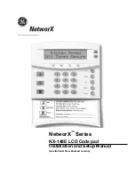
This is the GE
Alliance Arming Station Installation Instructions
for models AL-1111 (four-line LCD) and AL-1116 (four-line
LCD with Smart Card reader). These units are used with Alliance
control panels to control security system alarm and access func-
tions. Features include:
• Beeper.
• Integrated tamper switch.
• Four-line liquid crystal display (LCD).
• Multiple text formats.
• Embedded Smart Card reader (AL-1116 only).
• Access and system status LEDs.
• One open collector output to drive a small relay (an external
UL Listed power supply is required for UL installations).
• One input for an egress function.
• Plastic hinged cover.
The unit may be used up to 5,000 ft. (1.5 km) from the control
panel or 4 door/elevator controller DGP.
Note:
An external UL Listed power supply is required for UL
installations.
Installation
To install the unit, do the following:
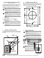
1.
The cover is hinged at the bottom. To open, grasp the cover
at the sides or the top and pull gently. The cover will swing
down on its pins (
). To remove the cover, gently pry
one of the pins away from the body of the unit and pull.
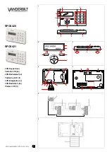
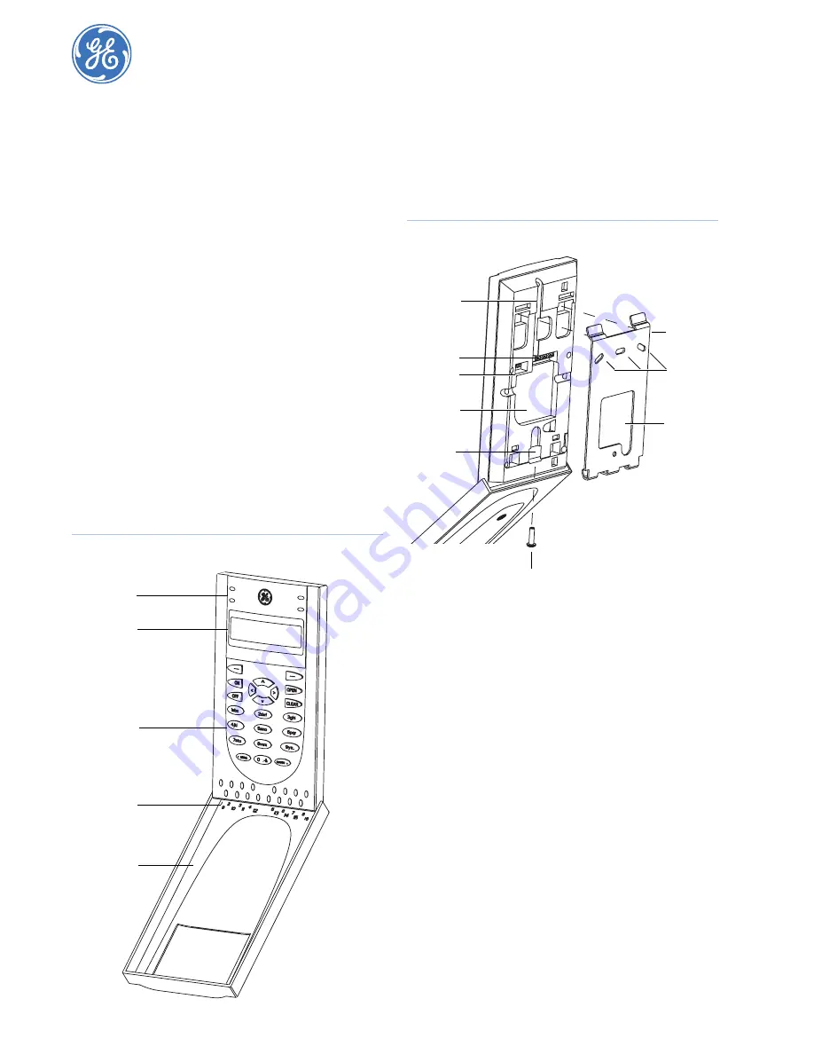
Figure 1. Unit front
2.
The metal mounting plate at the back of the unit is held by a
locking screw (
). To remove the mounting plate,
loosen the screw by at least 0.3 in. (8 mm), slide the
mounting plate down, and then pull the bottom of the
mounting plate away from the body of the unit.
Figure 2. Unit back and mounting plate
3.
Attach the mounting plate to the mounting surface using the
three screws provided.
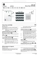
4.
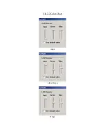
Set the RAS address using DIP switches 1 though 4 (see
5.
Set the system bus termination switch using DIP switch 5, if
required.
6.
Wire the COMMS system bus cabling (see
Note:
All power should be turned off to the control panel before
wiring the unit.
7.
Insert plastic cable entry blanking plugs (provided) into the
back of the unit to blank any unused cable entry channels
(
8.
Place the unit onto the mounting plate and move the unit
down about 0.3 in. (8 mm) to lock in place.
9.
Tighten the locking screw at the base of the unit until firm.
This will also ensure that the tamper switch (
) is
properly secured. Do not overtighten the screw.
Power
Fault
Access
Alarm
Status LEDs
LCD screen
Keypad
Area LEDs
Cover
Terminals
Cable
Tamper
switch
Mounting
holes
Mounting
plate
Cable
entry
entry
Cable
entry
Locking screw
DIP
switches