1040972B • February 2007
Copyright © 2007, GE Security Inc.
8-Area LCD RAS • AL-1103, AL-1108
Installation Instructions
Introduction
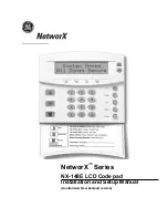
This is the GE
8-Area LCD RAS Installation Instructions
for
models AL-1103 and AL-1108. The RAS is the primary user
interface for navigating system programming, doing simple data
entry, and controlling the Alliance system alarm and access
control functions. The scrolling text, Liquid Crystal Display
(LCD) displays data entry, system status messages, programming
menus, and function options. These can be accessed and selected
through the alphanumeric digital keypad (
Figure 1
). The
AL-1108 model is also fitted with a card reader option.
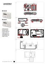
Figure 1. RAS components
The LCD is backlit and the keypad is low-level illuminated, or in
case of poor lighting conditions, may be programmed for high-
level illumination. The LCD backlight remains illuminated for
30 seconds after the last key press. The keypad high-level illumi-
nation remains active for four minutes after the last key press.
You can program the eight red area LEDs (four on each side of
the keypad) in
Figure 2
to indicate the status for areas 1 to 8 or
areas 9 to 16. The four larger status LEDs indicate power (green),
system trouble (yellow), alarms red), and access (blue).
Figure 2. Cover LEDs
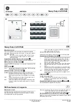
You can mount the RAS up to 5,000 ft. (1.5 km) from the control
panel. If the distance between the RAS and the control panel
does not exceed 328 ft. (100 m), you can power the RAS using
the +12V and 0V terminals from the control panel. When the
distance exceeds 328 ft. (100 m), use the AUX PWR terminal
from a DGP or an auxiliary power supply. If you use AUX PWR,
you must connect the 0V from the control panel to the 0V on the
DGP or auxiliary power supply.
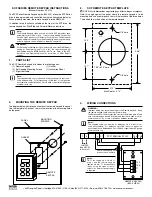
Installation
To install the unit, do the following:
1.
Locate the cover lock screw on the bottom of the unit and
unscrew it until you can lift the cover off the mounting plate
(
Figure 1
).
2.
Use the mounting plate to locate and install mounting
anchors where needed (
Figure 3
).
Figure 3. Mounting plate
3.
Pull the wiring through the cable entry and screw the
mounting plate to the wall. If a pry-off tamper is required,
use a screw in the tamper hole on the mounting plate
(
Figure 3
).
4.
Wire the circuit board. Turn off all power to the control
panel before wiring the unit. See
Wiring
on page 2.
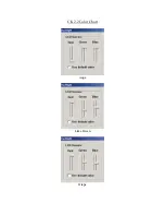
5.
Set the DIP switches as needed. See
DIP switch settings
on
page 3.
6.
Insert the cover in the guides at the top of the mounting
plate (
Figure 3
), pull the cover down, and tighten the cover
lock screw at the bottom of the unit (
Figure 1
).
7.
Refer to your Alliance system programming documentation
for keypad operation and system programming.
Mounting plate
Cover
LCD
Keypad
Door
Cover lock screw
Powe
r Fault
Alarm
Access
Status LEDs
Area LEDs
Area
LEDs
CAUTION:
You must be free of static electricity
before handling circuit boards. Wear a
grounding strap or touch a bare metal
surface to discharge static electricity.
Tamper
screw
Cover
guides
Mounting holes
Mounting holes
Cable entry