background image

GE Consumer & Industrial

Electrical Distribution

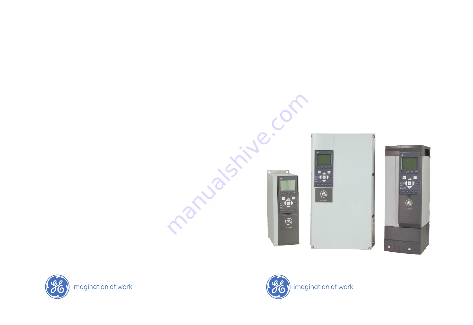
AF-650 GP

TM

General Purpose Drive

Desi

gn Guide

The instructions do not purport to cover all details or variations in equipment nor to provide for every possible
contingency to be met in connection with installation, operation or maintenance. Should further information be
desired or should particular problems arise which are not covered sufficiently for the purchaser’s purposes, the
matter should be referred to the GE company.

AF-650 GP is a trademark of the General Electric Company.

GE Consumer & Industrial
41 Woodford Avenue
Plainville, CT 06062

www.geelectrical.com/drives

130R0361

*MG34H102*

DET-618

Summary of Contents for AF-650 GP Series

Page 1: ...be met in connection with installation operation or maintenance Should further information be desired or should particular problems arise which are not covered sufficiently for the purchaser s purpose...

Page 2: ...0 Local Hand and Remote Auto Control 21 Reference Limits 23 Scaling of Preset References and Bus References 23 Scaling of Analog and Pulse References and Feedback 24 Dead Band Around Zero 24 Speed PID...

Page 3: ...6X 108 Cooling and Airflow 111 7 Electrical Installation 117 Connections Unit Sizes 1x 2x and 3x 117 Connection to Mains and Earthing 118 Motor Connection 121 Relay Connection 124 Connections Unit Si...

Page 4: ...Slot B 167 General Purpose Input Output Module OPCGPIO 168 OPCENC Encoder Option Module 171 OPCRES Resolver Option Module 173 OPCRLY Relay Option Module 174 OPC24VPS 24V DC External Supply Module 176...

Page 5: ...AF 650 GP Design Guide 4 1...

Page 6: ...8 provides information on how to programme and includes complete parameter descriptions The AF 650 GP Profibus Operating Instructions DET 629 provide the information required for controlling monitorin...

Page 7: ...Minute RPM Regenerative terminals Regen Second s Synchronous Motor Speed ns Torque limit TLIM Volts V 1 1 4 Definitions Frequency converter Coast The motor shaft is in free mode No torque on motor ID...

Page 8: ...tor frequency nameplate data IM The motor current IM N The rated motor current nameplate data nM N The rated motor speed nameplate data ns Synchronous motor speed ns 2 par F 04 60 s par P 01 PM N The...

Page 9: ...f the frequency converter There are two types of analog inputs Current input 0 20 mA and 4 20 mA Voltage input 0 10 V DC Voltage input 10 10 V DC Analog Outputs The analog outputs can supply a signal...

Page 10: ...while another Set up is active SFAVM Switching pattern called Stator Flux oriented Asynchronous Vector Modulation par F 37 Adv Switching Pattern Slip Compensation The frequency converter compensates f...

Page 11: ...se control I1 x cos 1 IRMS I1 IRMS since cos 1 1 The power factor indicates to which extent the frequency converter imposes a load on the mains supply The lower the power factor the higher the IRMS fo...

Page 12: ...ntional start make it necessary to ensure that no unintended start occurs these stop functions are not sufficient In such cases the mains supply must be disconnected 2 The motor may start while settin...

Page 13: ...ies with the relevant EU directives The CE label says nothing about the specifications or quality of the product Frequency converters are regulated by three EU directives The machinery directive 98 37...

Page 14: ...rter and CE Labelling CE labelling is a positive feature when used for its original purpose i e to facilitate trade within the EU and EFTA However CE labelling may cover many different specifications...

Page 15: ...air ventilation keeping aggressive gases away from the frequency converter An extra protection in such areas is a coating of the printed circuit boards which can be ordered as an option NB Mounting f...

Page 16: ...12 Chassis Chassis Heavy duty HD rat ed power 160 overload torque 5 5 7 5 kW 200 240 V 11 15 kW 380 480V 11 15 kW 525 600 V 11 kW 200 250 V 18 5 22 kW 380 480V 18 5 22 kW 525 600 V 11 22 kW 525 690 V...

Page 17: ...690 V 525 690 V 132 200 kW at 400 V 380 480 V 160 315 kW at 690 V 525 690 V Unit Size 51 52 61 63 62 64 Unit Size protection IP 21 54 00 21 54 21 54 NEMA Type 1 Type 12 Chassis Type 1 Type 12 Type 1 T...

Page 18: ...ion is used in applications where the torque on motor output shaft is controlling the application as tension control Torque control can be selected in par H 40 either in Advanced Vector Control open l...

Page 19: ...ol The output of the motor control is then limited by the maximum frequency limit If par H 40 Configuration Mode is set to Speed closed loop 1 the resulting reference will be passed from the ramp limi...

Page 20: ...ing system is fed through the ramp and speed limitations as determined by the parameter settings indicated An estimated speed feedback is generated to the Speed PID to control the output frequency The...

Page 21: ...k par H 41 Motor Control Principle configuration When this mode has been selected the reference will use the Nm unit It requires no torque feedback since the actual torque is calculated on the basis o...

Page 22: ...up O 5 serial communication Active Reference and Configuration Mode The active reference can be either the local reference or the remote reference In par F 02 Operation Method the local reference can...

Page 23: ...le analog references variable digital pulse references and various serial bus references in whatever unit the frequency converter is controlled Hz RPM Nm etc 2 Y the relative reference A sum of one fi...

Page 24: ...References and Bus References Preset references are scaled according to the following rules When par F 50 Reference Range 0 Min Max 0 reference equals 0 unit where unit can be any unit e g rpm m s bar...

Page 25: ...ent mA Par E 60 Term 29 Low Frequency Hz Par E 65 Term 33 Low Frequency Hz P2 Maximum input value Maximum reference value Maximum reference value Par AN 15 Ter minal 53 High Ref Feedb Val ue Par AN 15...

Page 26: ...band but a reference endpoint of e g P1 1V 0 RPM will result in a 1V to 1V dead band in this case provided that the end point P2 is placed in either Quadrant 1 or Quadrant 4 Case 1 Positive Reference...

Page 27: ...Clamping rules This Case shows how Reference input with limits outside Max Max limits clamps to the inputs low and high limits before addition to External reference And how the External reference is...

Page 28: ...tive ACTIVE N A 1 Speed closed loop N A ACTIVE N A ACTIVE 2 Torque N A N A N A Not Active 3 Process Not Active ACTIVE ACTIVE Note N A means that the specific mode is not available at all Not Active me...

Page 29: ...ted to allow setting of the reasonable differentiation time for slow changes and a suitably quick gain for quick changes Par PI 06 Speed PID Lowpass Filter Time A low pass filter that dampens oscillat...

Page 30: ...onfigure the Speed Control and select the Motor Control principle Activation of Speed Control Par H 40 Configura tion Mode 1 Speed closed loop Selection of Motor Control Principle Par H 41 Motor Con t...

Page 31: ...ts of this setting 3 4 3 Process PID Control The Process PID Control can be used to control application parameters that can be measured by a sensor i e pressure temperature flow and be affected by the...

Page 32: ...ck reaction However too small value may lead to oscillations Par PI 35 Process PID Differentiation Time Provides a gain proportional to the rate of change of the feedback A setting of zero disables th...

Page 33: ...he temperature increases the ventilation speed is increased as well so as to generate more air When the temperature drops the speed is reduced The transmitter used is a temperature sensor with a worki...

Page 34: ...E Switches are sensitive Make a power cycling keeping default setting of V 5 Scale analog inputs used for reference and feedback Set terminal 53 low voltage Set terminal 53 high voltage Set terminal 5...

Page 35: ...ed when the amplitude of oscillation is quite small Then we back off from this gain again as shown in Table 1 Ku is the gain at which the oscillation is obtained Type of Control Proportional Gain Inte...

Page 36: ...ency converter enclosure as well as on the motor enclosure This is best done by using integrated screen clamps so as to avoid twisted screen ends pigtails These increase the screen impedance at higher...

Page 37: ...nment Indus trial Category C1 First environment Home and office Category C2 First environment Home and office With RFI AF 650 GP 0 37 kW 200 240 V 50 m 150 m 150 m No Yes 0 75 kW 380 480 V 50 m 150 m...

Page 38: ...dustrial environments Class B Second environment industrial environment EN IEC61000 6 4 Emission standard for industrial environments Class A Group 1 3 5 4 Immunity Requirements The immunity requireme...

Page 39: ...ions on PELV supplies All control terminals and relay terminals 01 03 04 06 comply with PELV Protective Extra Low Voltage Does not apply to grounded Delta leg above 400 V Galvanic ensured isolation is...

Page 40: ...ed on the nameplate for the specific unit Leakage Current The earth leakage current from the frequency converter exceeds 3 5 mA To ensure that the earth cable has a good mechanical connection to the e...

Page 41: ...ed in the motor by changing the loss conditions in the motor The AC brake function cannot be used in applications with high cycling frequency since this will overheat the motor par B 10 2 DC brake An...

Page 42: ...630 1000 kW 600 40 10 Table 3 3 Braking at Heavy duty HD torque level 1 500 kW at 86 braking torque 560 kW at 76 braking torque 2 500 kW at 130 braking torque 560 kW at 115 braking torque GE offers br...

Page 43: ...2 x 100 Pmotor x Mbr x DRIVE x motor motor is typically at 0 90 DRIVE is typically at 0 98 For 200 V 480 V and 600 V frequency converters Rrec at 160 braking torque is written as 200V Rrec 107780 Pmot...

Page 44: ...or relay2 or a programmed digital output terminal 27 or 29 is required Normally this output must be closed for as long as the frequency converter is unable to hold the motor e g because of too big lo...

Page 45: ...be obtained The hoist mechanical brake strategy is based on a 3 step sequence where motor control and brake release are synchronized in order to obtain the smoothest possible brake release 3 step sequ...

Page 46: ...re linked in pairs called states This means that when event 1 is fulfilled attains the value TRUE action 1 is executed Afterthis the conditionsofevent 2 will beevaluatedandifevaluatedTRUE action 2 wil...

Page 47: ...y to be dissipated as a loss in the frequency converter the motor and the installation 3 Incorrect slip compensation setting may cause higher DC link voltage The control unit may attempt to correct th...

Page 48: ...d The frequency converter Electronic Thermal Overload function measures actual current speed and time to calculate motor tem perature and protect the motor from being overheated Warning or trip An ext...

Page 49: ...SILCL 2 PFH Probability of Dangerous failure per Hour 7e 10FIT 7e 19 h SFF Safe Failure Fraction 99 HFT Hardware Fault Tolerance 0 1oo1D architecture Abbreviations related to Functional Safety Abbrevi...

Page 50: ...cor responding to the inside of an IP54 encapsulation must be ensured An obvious solution if there is a risk of conductive contamination in the operating environment would be to mount the devices in...

Page 51: ...ltage must be reapplied to terminal 37 text Safe Stop activated is still displayed second a Reset signal must be created via bus Digital I O or Reset key on inverter By default the Safe Stop functions...

Page 52: ...erminal 37 Safe Stop is set to 3 1 Remove the 24 V DC voltage supply to terminal 37 by the interrupt device while the motor is driven by the AF 650 GP i e mains supply is not interrupted The test step...

Page 53: ...AF 650 GP Design Guide 52 4...

Page 54: ...13 5 13 5 13 5 13 5 13 5 13 5 Efficiency 4 0 94 0 94 0 95 0 96 0 96 0 96 0 96 0 25 3 7 kW only available as 160 heavy duty HD Mains Supply 3 x 200 240 VAC AF 650 GP 7 5 HP 10 HP 15 HP High Normal Load...

Page 55: ...9 31 7 31 7 41 4 41 4 51 5 51 5 61 2 Max input current Continuous 3 x 200 240 V A 54 68 68 80 80 104 104 130 130 154 Intermittent 60 sec overload 3 x 200 240 V A 81 74 8 102 88 120 114 156 143 195 169...

Page 56: ...00 V AC KVA 0 9 1 7 2 8 3 9 5 0 6 9 9 0 11 0 Continuous KVA 460 V AC KVA 0 9 1 7 2 7 3 8 5 0 6 5 8 8 11 6 Max cable size mains motor brake AWG 2 mm2 24 10 AWG 0 2 4 mm2 24 10 AWG 0 2 4 mm2 Max input c...

Page 57: ...AC KVA 16 6 22 2 22 2 26 26 30 5 30 5 42 3 Continuous KVA 460 V AC KVA 21 5 27 1 31 9 41 4 Max input current Continuous 3 x 380 440 V A 22 29 29 34 34 40 40 55 Intermittent 60 sec over load 3 x 380 44...

Page 58: ...7 104 128 Max input current Continuous 3 x 380 440 V A 55 66 66 82 82 96 96 133 133 161 Intermittent 60 sec overload 3 x 380 440 V A 82 5 72 6 99 90 2 123 106 144 146 200 177 Continuous 3 x 441 480 V...

Page 59: ...A 123 147 147 180 180 218 218 274 274 333 Continuous KVA at 460 V KVA 127 151 151 191 191 241 241 288 288 353 Continuous KVA at 480 V KVA 139 165 165 208 208 262 262 313 313 384 Max input current Cont...

Page 60: ...554 Continuous KVA at 460 V KVA 353 430 430 470 470 540 540 582 Continuous KVA at 480 V KVA 384 468 468 511 511 587 587 632 Max input current Continuous at 400 V A 472 590 590 647 647 733 684 787 Cont...

Page 61: ...09 909 1005 1005 1195 1195 1325 Max input current Continuous at 400 V A 779 857 857 964 964 1090 1090 1227 1227 1422 1422 1675 Continuous at 460 480 V A 711 759 759 867 867 1022 1022 1129 1129 1344 13...

Page 62: ...4 3 6 2 7 8 9 8 14 4 17 6 Continuous kVA 525 V AC kVA 1 7 2 8 3 9 5 0 6 1 9 0 11 0 Continuous kVA 575 V AC kVA 1 7 2 7 3 9 4 9 6 1 9 0 11 0 Max cable size mains motor brake AWG 2 mm2 24 10 AWG 0 2 4...

Page 63: ...41 0 41 0 51 4 Continuous kVA 575 V AC kVA 17 9 21 9 21 9 26 9 26 9 33 9 33 9 40 8 40 8 51 8 Max cable size IP20 mains motor load share and brake AWG 2 mm2 16 6 35 2 Max cable size IP21 55 66 mains m...

Page 64: ...575 V AC kVA 51 8 61 7 61 7 82 7 82 7 99 6 99 6 130 5 Max cable size IP20 mains motor AWG 2 mm2 50 1 95 4 0 150 300mcm Max cable size IP20 load share brake AWG 2 mm2 50 1 95 4 0 Max cable size IP21 55...

Page 65: ...t 60 sec over load 3 x 551 690 V A 20 8 19 8 28 8 24 2 35 2 29 7 43 2 37 4 Continuous KVA at 550 V KVA 13 3 18 1 18 1 21 9 21 9 26 7 26 7 34 3 Continuous KVA at 575 V KVA 12 9 17 9 17 9 21 9 21 9 26 9...

Page 66: ...sec overload 3 x 551 690 V A 51 45 1 61 5 57 2 78 68 2 93 91 3 124 5 110 Continuous KVA at 550 V KVA 34 3 41 0 41 0 51 4 51 4 61 9 61 9 82 9 82 9 100 0 Continuous KVA at 575 V KVA 33 9 40 8 40 8 51 8...

Page 67: ...191 191 241 241 289 Continuous KVA at 575 V KVA 108 130 130 154 154 191 191 241 241 289 Continuous KVA at 690 V KVA 129 157 157 185 185 229 229 289 289 347 Max input current Continuous at 550 V A 110...

Page 68: ...43 398 378 448 Continuous KVA at 690 V KVA 347 411 411 478 454 538 Max input current Continuous at 550 V A 299 355 355 408 381 453 Continuous at 575 V A 286 339 339 390 366 434 Continuous at 690 V A 2...

Page 69: ...A at 575 V KVA 408 498 498 568 568 627 Continuous KVA at 690 V KVA 490 598 598 681 681 753 Max input current Continuous at 550 V A 413 504 504 574 574 607 Continuous at 575 V A 395 482 482 549 549 607...

Page 70: ...t Continuous at 550 V A 642 743 743 866 866 962 Continuous at 575 V A 613 711 711 828 828 920 Continuous at 690 V A 613 711 711 828 828 920 Max cable size motor mm2 AWG2 8x150 8x300 mcm Max cable size...

Page 71: ...5107 18281 Estimated power loss at 690V W 4 14457 16375 15899 19207 F3 F4 Max added losses CB or Disconnect Contactor 556 665 634 863 Max panel options losses 400 Weight Unit Size IP21 IP 54 kg 1246 1...

Page 72: ...ering not more than 100 000 RMS symmetrical Amperes 240 480 600 690 V maximum Motor output U V W Output voltage 0 100 of supply voltage Output frequency 0 25 75 kW 0 1000 Hz Output frequency 90 1000 k...

Page 73: ...tal inputs Programmable digital inputs 4 6 1 Terminal number 18 19 271 291 32 33 Logic PNP or NPN Voltage level 0 24 V DC Voltage level logic 0 PNP 5 V DC Voltage level logic 1 PNP 10 V DC Voltage lev...

Page 74: ...age level see section on Digital input Maximum voltage on input 28 V DC Input resistance Ri approx 4 k Pulse input accuracy 0 1 1 kHz Max error 0 1 of full scale Encoder input accuracy 1 110 kHz Max e...

Page 75: ...AC 15 1 on 4 5 NO Inductive load cos 0 4 240 V AC 0 2 A Max terminal load DC 1 1 on 4 5 NO Resistive load 80 V DC 2 A Max terminal load DC 13 1 on 4 5 NO Inductive load 24 V DC 0 1A Max terminal load...

Page 76: ...ng for high ambient temperature see section on special conditions Minimum ambient temperature during full scale operation 0 C Minimum ambient temperature at reduced performance 10 C Temperature during...

Page 77: ...me a 55 kW 380 480 VAC frequency converter at 25 load at 50 speed The graph is showing 0 97 rated efficiency for a 55 kW drive is 0 98 The actual efficiency is then 0 97x0 98 0 95 Efficiency of the mo...

Page 78: ...tance The natural induction causes an overshoot UPEAK in the motor voltage before it stabilises itself at a level depending on the voltage in the intermediate circuit The rise time and the peak voltag...

Page 79: ...74 0 637 AF 650 GP 230V 30 HP Cable length m Mains voltage V Rise time sec Upeak kV du dt kV sec 15 240 0 194 0 626 2 581 50 240 0 252 0 574 1 822 150 240 0 488 0 538 0 882 AF 650 GP 230V 40 HP Cable...

Page 80: ...5 HP Cable length m Mains voltage V Rise time sec Upeak kV du dt kV sec 36 480 0 312 2 846 100 480 0 556 1 250 1 798 150 480 0 608 1 230 1 618 AF 650 GP 460V 30 HP Cable length m Mains voltage V Rise...

Page 81: ...MG 1 1998 Part 30 2 2 8 for general purpose motors 90 200 kW 380 480 V Cable length Mains voltage Rise time Peak voltage du dt 30 metres 400 V 0 34 sec 1040 V 2447 V sec 250 800 kW 380 480 V Cable le...

Page 82: ...ting depends on the switching pattern which can be set to 60 AVM or SFAVM in par F 37 Adv Switching Pattern Unit Sizes 1x 60 AVM Pulse Width Modulation Illustration 4 2 Derating of Iout for different...

Page 83: ...f Iout for different TAMB MAX for Unit Size 2x using 60 AVM in Normal torque mode 110 over torque Illustration 4 9 Derating of Iout for different TAMB MAX for Unit Size 2x using SFAVM in Normal torque...

Page 84: ...in Normal torque mode 110 over tor que Illustration 4 15 Derating of Iout for different TAMB MAX for Unit Size3x usingSFAVMinNormaltorquemode 110 overtorque Illustration 4 16 Output current derating w...

Page 85: ...80 V using 60 AVM in Normal torque mode 110 over torque Illustration 4 21 Derating of Iout for different TAMB MAX for Unit Size 4x at 480 V using SFAVM in Normal torque mode 110 over torque 60 AVM Pul...

Page 86: ...it Size 4x at 690 V using 60 AVM in High torque mode 160 over torque Note 400 HP only SFAVM Stator Frequency Asyncron Vector Modulation 525 690 V P315 Illustration 4 27 Derating of Iout for different...

Page 87: ...ent TAMB MAX for Unit Size 5x and 6x at 480 V using 60 AVM in Normal torque mode 110 over torque Illustration 4 33 Derating of Iout for different TAMB MAX for Unit Size 5x and 6x at 480 V using SFAVM...

Page 88: ...put current Iout should be derated in accordance with the shown diagram Illustration 4 38 Derating ofoutput currentversus altitude atTAMB MAX for unit sizes 1x 2x and3x At altitudesabove 2km pleasecon...

Page 89: ...ing and maximum torque with forced cooling at all speeds Maximum load for a standard motor at 40 C driven by an AF 600 FP drive Legend Typical torque at VT load Max torque with forced cooling Max torq...

Page 90: ...overheating it must be ensured that the ambient temperature does not exceed the maximum temperature stated for the frequency converter and that the 24 hour average temperature is not exceeded Locate...

Page 91: ...31 32 33 34 130BA810 10 IP20 Open Chassis IP20 Open Chassis Nema 12 Nema 12 Nema 12 IP20 IP20 Nema 12 Nema 12 IP20 Open Chassis IP20 Open Chassis Top and bottom mounting holes 24 33 and 34 only AF 650...

Page 92: ...242 mm 242 mm 165 mm 230 mm 308 mm 370 mm 308 mm 370 mm Width of back plate with one C op tion B 130 mm 130 mm 170 mm 170 mm 242 mm 242 mm 242 mm 205 mm 230 mm 308 mm 370 mm 308 mm 370 mm Width of bac...

Page 93: ...0 100 100 100 200 100 200 200 225 200 225 b mm 100 100 100 100 200 100 200 200 225 200 225 Table 5 1 1 Drill holes in accordance with the measurements given 2 You must provide screws suitable for the...

Page 94: ...maximum current from the frequency converter Ensure that the drive is properly protected per local regulations 6 1 2 Receiving the Frequency Converter When receiving the frequency converter please mak...

Page 95: ...a bar to avoid bending the lifting holes of the frequency converter Illustration 6 2 Recommended lifting method 4X and 5X Unit Sizes The lifting bar must be able to handle the weight of the frequency...

Page 96: ...Recommended lifting method Unit Size 62 460V 1000 to 1200 HP 575 600V 1250 to 1350 HP Illustration 6 5 Recommended lifting method Unit Size 63 460V 600 to 900 HP 575 600V 900 to 1150 HP Illustration 6...

Page 97: ...Please note airflow directions 6 1 5 Mechanical Dimensions AF 650 GP Design Guide 96 6...

Page 98: ...Please note airflow directions AF 650 GP Design Guide 97 6...

Page 99: ...Please note airflow directions AF 650 GP Design Guide 98 6...

Page 100: ...Please note airflow directions AF 650 GP Design Guide 99 6...

Page 101: ...Unit size 61 IP 21 54 NEMA 1 12 Unit size 63 IP 21 54 NEMA 1 12 1 Minimum clearance from ceiling AF 650 GP Design Guide 100 6...

Page 102: ...Unit size 62 IP 21 54 NEMA 1 12 Unit size 64 IP 21 54 NEMA 1 12 1 Minimum clearance from ceiling AF 650 GP Design Guide 101 6...

Page 103: ...104 kg 104 kg 151 kg 151 kg 91 kg 138 kg Mechanical dimensions Unit Sizes 4 and 5 Unit size 51 52 61 62 63 64 250 400 kW 380 480 V 355 560 kW 525 690 V 250 400 kW 380 480 V 355 560 kW 525 690 V 450 63...

Page 104: ...glands in IP 21 Nema 1 and IP 54 Nema 12 drive types Lifting bar to lift the unit rod or tube max 25 mm 1 inch able to lift minimum 400 kg 880 lbs Crane or other lifting aid to place the frequency con...

Page 105: ...62 Illustration 6 12 Space in front of IP21 Nema 1 and IP54 Nema drive types for unit size 64 Wire access Ensure that proper cable access is present including necessary bending allowance As the IP00...

Page 106: ...8 68 2 7 68 2 7 C 173 6 8 273 10 8 15 0 6 16 0 6 D 179 7 0 279 11 0 20 7 0 8 22 0 8 E 370 14 6 370 14 6 363 14 3 363 14 3 F 300 11 8 300 11 8 293 11 5 293 11 5 G 222 8 7 226 8 9 215 8 4 218 8 6 H 139...

Page 107: ...of the terminals into consideration when designing the cable access Illustration 6 14 IP21 NEMA Type 1 and IP54 NEMA Type 12 drive type power connection positions Illustration 6 15 IP21 NEMA type 1 a...

Page 108: ...tration 6 17 IP00 Open Chassis drive type power connection positions Note that the power cables are heavy and difficult to bend Consider the optimum position of the frequency converter for ensuring ea...

Page 109: ...6 2 5 Terminal Locations Unit Sizes 6X Terminal locations Unit Sizes 61 and 63 Illustration 6 19 Terminal locations Inverter Cabinet 61 and 63 front left and right side view The gland plate is 42 mm b...

Page 110: ...ew The gland plate is 42 mm below 0 level 1 Ground bar Terminal locations Rectifier Unit Sizes 61 62 63 and 64 61 62 63 64 Illustration 6 21 Terminal locations Rectifier Left side front and right side...

Page 111: ...with circuit breaker molded case switch Unit Sizes 63 and 64 Illustration 6 23 Terminal locations Options Cabinet with circuit breaker molded case switch Left side front and right side view The gland...

Page 112: ...ated from other components installed inside the enclosure The total required air flow must be calculated so that the appropriate fans can be selected Some enclosure manufacturers offer software for pe...

Page 113: ...t Size 4X Derating vs Pressure Change Drive air flow 450 cfm 765 m3 h Illustration 6 25 Unit Size 5X Derating vs Pressure Change Small Fan 350 HP 460V and 500 550 HP 690 V Drive air flow 650 cfm 1105...

Page 114: ...m Mark the mounting holes carefully using the mounting template on the wall and drill the holes as indicated Ensure proper distance to the floor and the ceiling for cooling A minimum of 225 mm 8 9 inc...

Page 115: ...and plate must be fitted to the frequency converter to ensure the specified protection degree as well as ensuring proper cooling of the unit If the gland plate is not mounted the frequency converter m...

Page 116: ...Unit Size 61 Unit Size 62 Unit Size 63 Unit Size 64 Unit Size 61 to 64 Cable entries viewed from the bottom of the frequency converter 1 Place conduits in marked areas AF 650 GP Design Guide 115 6...

Page 117: ...tom the glands and cables can be mounted before the frequency converter is placed on the pedestal 6 2 9 IP21 Drip Shield Installation Unit Sizes 41 and 42 To comply with the IP21 rating a separate dri...

Page 118: ...ns Brake resistor load sharing cables 4 5 Nm Motor cables 4 5 Nm Relay 0 5 0 6 Nm Earth 2 3 Nm 23 5 5 7 5 kW 11 15 kW Mains Brake resistor load sharing Motor cables 1 8 Nm Relay 0 5 0 6 Nm Earth 2 3 N...

Page 119: ...labelled MAINS at the bottom of the frequency converter 4 Attach mains wires to the mains plug connector 5 Support the cable with the supporting enclosed brackets NB Check that mains voltage correspo...

Page 120: ...on for Unit Sizes 12 and 13 IP20 Open Chassis drive types 230V to 5HP 460V 575V to 10HP Mains connector IP 55 66 Unit Size 15 Nema 12 or Nema 4 drive types 230V to 5HP 460V 575V to 10HP AF 650 GP Desi...

Page 121: ...size 24 IP20 Open Chassis drive type 230V 15 to 20HP 460V 575V 25 to 40HP Illustration 7 4 Mains connection for unit sizes 31 and 32 Nema 12 or Nema 4 drive types 230V 20 to 50HP 460V 40 to 100HP 575V...

Page 122: ...length must be reduced correspondingly Keep the motor cable as short as possible to reduce the noise level and leakage currents Switching frequency When frequency converters are used together with Si...

Page 123: ...5 to 25HP Illustration 7 11 Motor connection for for unit size 24 IP20 Open Chassis drive type 230V 15 to 20HP 460V 575V 25 to 40HP Illustration 7 12 Motor connection for unit sizes 31 and 32 Nema 12...

Page 124: ...t size 31 The sugges ted use of the holes are purely recommendations and other solutions are possible Illustration 7 17 Cable entry holes for unit size 32 The sugges ted use of the holes are purely re...

Page 125: ...normally open 01 03 break normally closed 04 05 make normally open 04 06 break normally closed Terminals for relay connection Unit Sizes 12 and 13 Terminals for relay connection Unit Sizes 15 21 and 2...

Page 126: ...Regen 19 Nm 168 in lbs 9 5 Nm 84 in lbs 19 Nm 168 in lbs M10 M8 M10 Table 7 1 Torque for terminals 7 2 2 Power Connections Cabling and Fusing NB Cables General All cabling must comply with national an...

Page 127: ...the screen connections with the largest possible surface area cable clamp This is done by using the supplied installation devices within the frequency converter Cable length and cross section The fre...

Page 128: ...42 1 AUX Relay 5 Brake 01 02 03 R R 04 05 06 81 82 2 Temp Switch 6 SMPS Fuse see fuse tables for part number 106 104 105 7 AUX Fan 3 Line 100 101 102 103 R S T L1 L2 L1 L2 91 92 93 8 Fan Fuse see fuse...

Page 129: ...Position of earth terminals IP00 Chassis 4X unit sizes Illustration 7 23 Position of earth terminals IP21 NEMA type 1 and IP54 NEMA type 12 Unit Size 42 NB Unit sizes 42 and 44 are shown in above exa...

Page 130: ...Illustration 7 24 Compact IP 21 NEMA 1 and IP 54 NEMA 12 Unit Size 51 Illustration 7 25 Position of earth terminals IP00 Chassis Unit Size 52 AF 650 GP Design Guide 129 7...

Page 131: ...See fuse tables for part numbers 2 Manual Motor Starters 7 SMPS Fuse See fuse tables for part numbers 3 30 A Fuse Protected Power Terminals 8 Manual Motor Controller fuses 3 or 6 pieces See fuse tabl...

Page 132: ...Motor 2 AUX Relay U V W 01 02 03 96 97 98 04 05 06 T1 T2 T3 3 NAMUR 7 NAMUR Fuse See fuse tables for part numbers 4 AUX Fan 8 Fan Fuses See fuse tables for part numbers 100 101 102 103 9 SMPS Fuses S...

Page 133: ...Motor 2 AUX Relay U V W 01 02 03 96 97 98 04 05 06 T1 T2 T3 3 NAMUR 7 NAMUR Fuse See fuse tables for part numbers 4 AUX Fan 8 Fan Fuses See fuse tables for part numbers 100 101 102 103 9 SMPS Fuses S...

Page 134: ...e LittleFuse KLK 5 or equivalent 7 3 Fuses Branch circuit protection In order to protect the installation against electrical and fire hazard all branch circuits in an installation switch gear machines...

Page 135: ...ze1 Min rated Voltage Type 0 5 2 10A 380 480 V type gG 3 5 20A 380 480 V type gG 7 5 10 32A 380 480 V type gG 15 25 63A 380 480 V type gG 30 80A 380 480 V type gG 40 100A 380 480 V type gG 50 125A 380...

Page 136: ...0R 20 25 2028220 125 KLN R125 A2K 125R Bussmann SIBA Littel fuse Ferraz Shawmut HP Type JFHR2 Type RK1 JFHR2 JFHR2 30 FWX 150 2028220 150 L25S 150 A25X 150 40 FWX 200 2028220 200 L25S 200 A25X 200 50...

Page 137: ...JJS 10 FNQ R 10 KTK R 10 LP CC 10 5K5 7K57 5 10 KTS R20 JKS 20 JJS 20 FNQ R 20 KTK R 20 LP CC 20 SIBA Littel fuse Ferraz Shawmut HP Type RK1 Type RK1 Type RK1 1 2 5017906 005 KLSR005 A6K 5R 3 5 501790...

Page 138: ...3 and 64 380 480 V AF 650 GP Bussmann PN Rating Siba 600 HP 170M8611 1100 A 1000 V 20 781 32 1000 650 HP 170M8611 1100 A 1000 V 20 781 32 1000 750 HP 170M6467 1400 A 700 V 20 681 32 1400 900 HP 170M64...

Page 139: ...it Sizes 61 62 63 and 64 525 690 V AF 650 GP Bussmann PN Rating Siba 900 HP 170M8611 1100 A 1000 V 20 781 32 1000 1000 HP 170M8611 1100 A 1000 V 20 781 32 1000 1200 HP 170M8611 1100 A 1000 V 20 781 32...

Page 140: ...sted Class J Dual Element Time Delay 15 A 6 3 10 A Fuse 600HP 1200HP 380 480 V LPJ 15 SP or SPI 15 A 600 V Any listed Class J Dual Element Time Delay 15 A 750HP 1350HP 525 690 V LPJ 20 SP or SPI 20 A...

Page 141: ...inals and the first common point of a phase The recommended common point is the motor terminals Unit Size 62 and 64 requirements Motor phase cable quantities must be multiples of 3 resulting in 3 6 9...

Page 142: ...converter Make sure that the impedance from frequency converter to building ground is lower that the grounding impedance of the machine This can be difficult for pumps Make a direct earth connection b...

Page 143: ...he cable must be placed to the left inside the frequency converter and tied down together with other control wires see picture Control card wiring path for the 43 Control card wiring for the 41 42 44...

Page 144: ...of low voltage will be given when 24 VDC has been connected however there will be no tripping Use 24 VDC supply of type PELV to ensure correct galvanic isolation type PELV on the control terminals of...

Page 145: ...awing Diagram showing all electrical terminals in section Electrical Installation Default setting S201 A53 OFF voltage input S202 A54 OFF voltage input S801 Bus termination OFF NB When changing the fu...

Page 146: ...Insert a screwdriver1 in the square hole 3 Insert the cable in the adjacent circular hole 4 Remove the screw driver The cable is now mounted to the terminal To remove the cable from the terminal 1 In...

Page 147: ...ag to the front of the fre quency converter 2 Connect terminals 18 27 and 37 to 24 V terminal 12 13 Default settings 18 Start par E 01 Terminal 18 Digital Input 9 27 Stop inverse par E 03 Terminal 27...

Page 148: ...ption Very long control cables and analogue signals may in rare cases and depending on installation result in 50 60 Hz earth loops due to noise from mains supply cables If this occurs it may be necess...

Page 149: ...rol terminals NB Control cables must be screened armoured See section entitled Earthing of Screened Armoured Control Cables for the correct termination of control cables 130BA681 10 130BA681 10 AF 650...

Page 150: ...installed brake chopper Terminal No Function 88 89 Loadsharing The connection cable must be screened and the max length from the frequency converter to the DC bar is limited to 25 metres 82 feet Load...

Page 151: ...ages up to 1099 VDC depending on the supply voltage may occur on the terminals Unit Size 5 Requirements The brake resistor s must be connected to the brake terminals in each inverter module 7 7 4 RS 4...

Page 152: ...up Software 3 Select in the network section the USB port 4 Choose Copy 5 Select the project section 6 Choose Paste 7 Choose Save as All parameters are now stored Data transfer from PC to drive via DC...

Page 153: ...d but not recommended See also paragraphs CE Labelling General Aspects of EMC Emission and EMC Test Results Good engineering practice to ensure EMC correct electrical installation Use only braided scr...

Page 154: ...Illustration 7 36 EMC correct electrical installation of a frequency converter in cabinet Illustration 7 37 Electrical connection diagram AF 650 GP Design Guide 153 7...

Page 155: ...assessing the physical design of the cable Transfer impedance ZT can be assessed on the basis of the following factors The conductibility of the screen material The contact resistance between the ind...

Page 156: ...keeping leads short e Cables for serial communication Eliminate low frequency noise currents between two frequency converters by connecting one end of the screen to terminal 61 This terminal is conne...

Page 157: ...ries Harmonic currents compared to the RMS input current Input current IRMS 1 0 I1 0 9 I5 0 4 I7 0 2 I11 49 0 1 To ensure low harmonic currents the frequency converter is equipped with intermediate ci...

Page 158: ...Activate the Auto Tune Performing an Auto Tune will ensure optimum performance The Auto Tune measures the values from the motor model equivalent diagram 1 Connect terminal 37 to terminal 12 2 Activat...

Page 159: ...e sure to mention number and alarm description NB Unsuccessful Auto Tune is often caused by incorrectly entering motor name plate data or a too big difference between the motor power size and the freq...

Page 160: ...ar E 01 Terminal 18 Digital Input 8 Start par F 16 par F 15 par F 03 par CL 14 8 1 2 Pulse Start Stop Terminal 18 par E 01 Terminal 18 Digital InputLatched start 9 Terminal 27 par E 03 Terminal 27 Dig...

Page 161: ...the frequency converter Before setting up the encoder the basic settings for a closed loop speed control system will be shown Encoder Connection to the frequency converter 24 V incremental encoder Ma...

Page 162: ...ast inverse 2 or Coast and Reset inverse 3 and program terminal 29 to Terminal mode 29 Output 1 and Torque limit stop 27 Description If a stop command is active via terminal 18 and the frequency conve...

Page 163: ...01 02 contact according to the programmed brake logic The output is now energized until STOP condition occurs If the frequency converter is in alarm or fault condition the output relay immediately cu...

Page 164: ...best adjustment of the frequency converter carry out auto tune on a cold motor Repeated auto tune runs may lead to a heating of the motor which results in an increase of the stator resistance Rs Norma...

Page 165: ...8 1 Ex 0 zero Set the timer 0 for constant running speed in par LC 20 Logic Controller Timer 0 Ex 2 sec Set Event 1 in par LC 51 Logic Controller Event 1 to True 1 Set Event 2 in par LC 51 Logic Cont...

Page 166: ...ation of the torque control After setting the basic settings the factory setting is optimised for most processes It is rarely necessary to optimise the torque proportional gain in par PI 12 and the to...

Page 167: ...ime PI 13 Default 0 02 sec Reference Handling Nm Reference 53 Limit 54 Reference range F 50 Min max 0 Terminal 53 Low Voltage AN 10 0V Default 0 07V Terminal 53 High Voltage AN 11 10V Terminal 53 Low...

Page 168: ...he drive Remove the Keypad the terminal cover and the Keypad frame from the frequency converter Fit the OPCxxx option card into slot B Connect the control cables and relieve the cable by the enclosed...

Page 169: ...ral Purpose I O Option Module is used for extension of digital and analog inputs and outputs of AF 650 GP Contents OPCGPIO must be fitted into slot B in the AF 650 GP OPCGPIO option module Extended fi...

Page 170: ...s in the OPCGPIO are galvanically isolated from other inputs outputs on the OPCGPIO but not from these on the control card of the drive If the digital inputs 7 8 or 9 are to be switched by use of the...

Page 171: ...impedance 10 k Max voltage 20 V Resolution for analog inputs 10 bit sign Accuracy of analog inputs Max error 0 5 of full scale Bandwidth AF 650 GP 20 Hz AF 650 GP 100 Hz 9 2 4 Digital Outputs Terminal...

Page 172: ...visible when removing the Keypad Reaction in case of an encoder error can be selected in par EC 61 Feedback Signal Monitoring None Warning or Trip The encoder option kit includes OPCENC Encoder Optio...

Page 173: ...Max cable length 150 m AF 650 GP Design Guide 172 9...

Page 174: ...0 Poles 2 2 ResolverInputVoltage Par RS 51 Input Voltage 2 0 8 0 Vrms 7 0Vrms Resolver Input Fre quency Par RS 52 Input Frequency 2 15 kHz 10 0 kHz Transformation ratio Par RS 53 Transformation Ratio...

Page 175: ...d Motor data sheet mH Par P 01 Motor Poles Motor data sheet Par H 46 Back EMF at 1000 RPM Motor data sheet Par H 47 Motor Angle Offset Motor data sheet Usually zero Par RS 50 Poles Resolver data sheet...

Page 176: ...Fit the OPCRLY Relay Option Module in slot B Connect the control cables and fasten the cables with the enclosed cable strips Make sure the length of the stripped wire is correct see the following dra...

Page 177: ...ble length 75 m Input capacitance load 10 uF Power up delay 0 6 s The inputs are protected Terminal numbers Terminal 35 external 24 V DC supply Terminal 36 external 24 V DC supply Follow these steps 1...

Page 178: ...rom the regenerative braking The resistor is selected in respect to its ohmic value its power dissipation rate and its physical size GE offers a wide variety of different resistors that are specially...

Page 179: ...AF 650 GP Design Guide 178 9...

Page 180: ...d to cover the top inlet Place the base part C at the bottom of the drive and use the clamps from the accessory bag to correctly fasten the cables Holes for cable glands Size 12 2x M25 and 3xM32 Size...

Page 181: ...oise thus corresponds to the switching frequency of the frequency converter The filter reduces the accel time of the voltage the peak load voltage UPEAK and the ripple current I to the motor which mea...

Page 182: ...g at high frequencies This can be achieved by connecting a large surface of the screen to ground for example by means of a cable clamp or a conductive cable gland It may be necessary to apply potentia...

Page 183: ...able the RS 485 cable must cross motor and brake resistor cables at an angle of 90 degrees The Drive protocol also referred to as Drive bus or Standard bus is the GE standard network It defines an acc...

Page 184: ...bits and the parity bit in total A character is completed by a stop bit thus consisting of 11 bits in all 10 4 2 Telegram Structure Each telegram begins with a start character STX 02 Hex followed by...

Page 185: ...checksum is calculated as an XOR function Before the first byte in the telegram is received the Calculated Checksum is 0 10 4 6 The Data Field The structure of data blocks depends on the type of teleg...

Page 186: ...meter command 15 14 13 12 0 0 0 0 No command 0 0 0 1 Read parameter value 0 0 1 0 Write parameter value in RAM word 0 0 1 1 Write parameter value in RAM double word 1 1 0 1 Write parameter value in RA...

Page 187: ...he defined command AK The master prompts for a parameter value when the PWE block contains no value To change a parameter value write write the new value in the PWE block and send from the master to t...

Page 188: ...nsfer decimals Par F 16 Motor Speed Low Limit Hz has a conversion factor of 0 1 To preset the minimum frequency to 10 Hz transfer the value 100 A conver sion factor of 0 1 means that the value transfe...

Page 189: ...9 SP 10 XC 11 DR 12 LG 13 CL 14 ID 15 AP 16 T 17 FB 18 PC 19 AO 20 BP 21 DN 22 PI 23 LC 24 EC 25 RS 26 BN 27 LN 28 EN 29 CB 30 CA 31 CD 32 10 5 1 Writing a Parameter Value Change par F 15 Motor Speed...

Page 190: ...alue Read the value in par F 07 Accel Time 1 PKE 1007 Hex Read parameter value in par F 07 Accel Time 1 IND 0000 Hex PWEHIGH 0000 Hex PWELOW 0000 Hex If the value in par F 07 Accel Time 1 is 10 s the...

Page 191: ...e query The master can address individual slaves or can initiate a broadcast message to all slaves Slaves return a message called a response to queries that are addressed to them individually No respo...

Page 192: ...ity Error Check Field Cyclical Redundancy Check CRC 10 8 2 Modbus RTU Message Structure The transmitting device places a Modbus RTU message into a frame with a known beginning and ending point This al...

Page 193: ...significant bit set to logic 1 In addition the slave places a unique code into the data field of the response message This tells the master what kind of error occurred or the reason for the exception...

Page 194: ...y Frequency converter ready 35 Coasting stop Safety closed 36 No alarm Alarm 37 Not used Not used 38 Not used Not used 39 Not used Not used 40 No warning Warning 41 Not at reference At reference 42 Ha...

Page 195: ...on code received in the query is not an allowable action for the server or slave This may be because thefunction code is only applicable to newer devices and was not implemented in the unit selected I...

Page 196: ...10 9 5 Conversion Factor The different attributes for each parameter can be seen in the section on factory settings Since a parameter value can only be transferred as a whole number a conversion facto...

Page 197: ...unction Reverse Explanation of the Control Bits Bits 00 01 Bits 00 and 01 are used to choose between the four reference values which are pre programmed in par C 05 Multi step Frequency 1 8 according t...

Page 198: ...ts the frequency converter to start the motor if the other starting conditions are met Make a selection in par O 53 Start Select to define how Bit 06 Ramp stop start gates with the corresponding funct...

Page 199: ...o error Triplock 07 No warning Warning 08 Speed reference Speed reference 09 Local operation Bus control 10 Out of frequency limit Frequency limit OK 11 No operation In operation 12 Drive OK Stopped a...

Page 200: ...ached the value in par F 18 Motor Speed Low Limit RPM or par F 17 Motor Speed High Limit RPM Bit 10 1 The output frequency is within the defined limits Bit 11 No operation in operation Bit 11 0 The mo...

Page 201: ...esponds to 100 Negative figures are formatted by means of 2 s complement The Actual Output frequency MAV is scaled in the same way as the bus reference The reference and MAV are scaled as follows 10 1...

Page 202: ...and if Relay 123 has been selected in par E 24 Function Relay When bit 01 1 the frequency converter is in State 1 Switching on inhibited Please refer to the PROFIdrive State Transition Diagram at the...

Page 203: ...bit 04 0 and bit 00 03 1 Bit 09 Jog 2 OFF ON Activation of the pre programmed speed in par O 91 Bus Jog 2 Speed JOG 2 is only possible if bit 04 0 and bit 00 03 1 Bit 10 Data invalid valid Is used to...

Page 204: ...g a PC about the status of a slave Bit Bit 0 Bit 1 00 Control not ready Control ready 01 Drive not ready Drive ready 02 Coasting Enable 03 No error Trip 04 OFF 2 ON 2 05 OFF 3 ON 3 06 Start possible S...

Page 205: ...the current speed of the motor corresponds to the set speed reference value Bit 09 Local operation Bus control Bit 09 0 indicates that the frequency converter has been stopped by means of the stop bu...

Page 206: ...OK Timer exceeded When bit 15 0 the timers for the thermal motor protection and electronic overload protection have not exceeded 100 When bit 15 1 one of the timers has exceeded 100 AF 650 GP Design...

Page 207: ...able Lengths And Cross Sections 71 Cable Positions 105 Cable length And Cross section 126 Cabling 125 Catch Up Slow Down 22 Ce Conformity And Labelling 12 Coasting 198 Coasting 6 197 Conducted Emissio...

Page 208: ...c Directive 89 336 eec 13 Emc Precautions 182 Emc Test Results 36 Emission Requirements 37 Equalising Cable 155 External 24 V Dc Supply 176 External Fan Supply 133 Extreme Running Conditions 46 F Flux...

Page 209: ...nection 121 Motor Feedback 20 Motor Name Plate 157 Motor Output 71 Motor Parameters 163 Motor Phases 46 Motor Protection 72 Motor Thermal Protection 199 Motor Thermal Protection 47 Motor Voltage 77 Mo...

Page 210: ...ircuit motor Phase Phase 46 Sine wave Filters 180 Space 103 Speed Pid 17 18 Speed Pid Control 27 Start stop 159 Static Overload In Advanced Vector Control Mode 46 Status Word 198 Status Word According...

Page 211: ...Voltage Reference Via A Potentiometer 160 W What Is Ce Conformity And Labelling 12 What Is Covered 13 Wire Access 104 AF 650 GP Design Guide 210...

Page 212: ...ncy to be met in connection with installation operation or maintenance Should further information be desired or should particular problems arise which are not covered sufficiently for the purchaser s...

Reviews: