background image

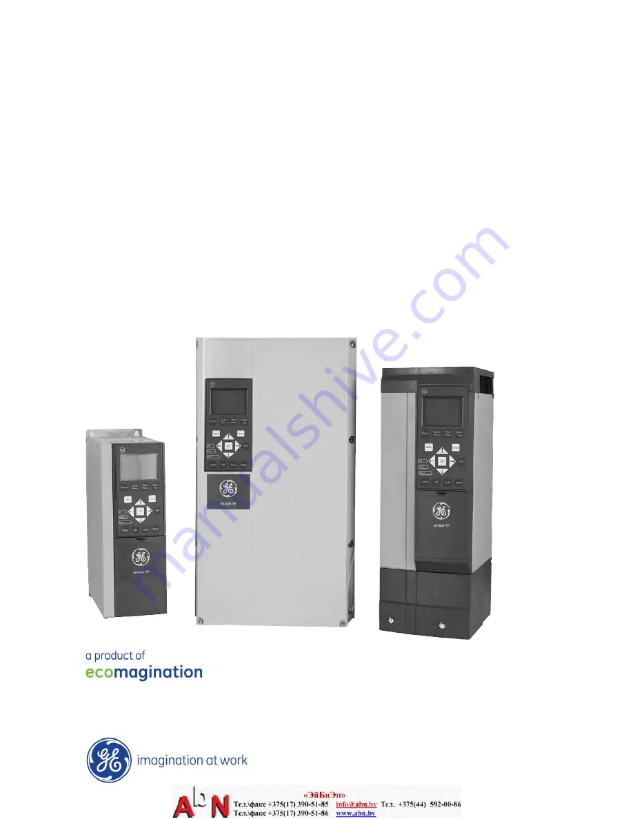
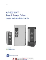
AF-600 FP

TM


Fan & Pump Drive 

Design and Installation Guide

The instructions do not purport to cover all details or variations in equipment nor to provide for every possible 
contingency to be met in connection with installation, operation or maintenance. Should further information be 

desired or should particular problems arise which are not covered sufficiently for the purchaser’s purposes, the 

matter should be referred to the GE company.

AF-600 FP is a trademark of the General Electric Company.

GE
41 Woodford Avenue
Plainville, CT 06062

www.geelectrical.com/drives

130R0412 

*MG14F122*

DET-768A

GE

Summary of Contents for AF-600 FP Series

Page 1: ...AF 600 FPTM Fan Pump Drive Design and Installation Guide GE ...

Page 2: ... remain charged even when the adjustable frequency drive is not powered To avoid electrical hazards disconnect AC line power any permanent magnet type motors and any remote DC link power supplies including battery backups UPS and DC link connections to other adjustable frequency drives Wait for the capacitors to fully discharge before performing any service or repair work The wait time required is...

Page 3: ...ch if not avoided may result in minor or moderate injury It may also be used to alert against unsafe practices CAUTION Indicates a situation that may result in equipment or property damage only accidents NOTE Indicates highlighted information that should be observed in order to avoid mistakes or operate equipment at less than optimal performance Approvals Table 1 2 Safety AF 600 FP Design and Inst...

Page 4: ...llation NEMA 3R Kit of Industrial Enclosures 3 5 2 4 4 Installation of IP00 to IP20 Kits 3 5 2 4 5 Installation of cable clamp bracket in open chassis drives 3 5 2 4 6 Installation on Pedestal 3 5 2 4 7 Installation of Line Power Shield for Adjustable Frequency Drives 3 6 2 4 8 USB Extension Kit 3 6 2 4 9 Installation of 4x or 5x Load Share Option 3 6 2 5 Electrical Installation 3 7 2 5 1 Requirem...

Page 5: ...ayout 5 1 4 1 2 Setting Keypad Display Values 5 2 4 1 3 Display 5 2 4 1 4 Navigation Keys 5 3 4 1 5 Operation Keys 5 3 4 2 Back Up and Copying Parameter Settings 5 3 4 2 1 Uploading Data to the Keypad 5 4 4 2 2 Downloading Data from the Keypad 5 4 4 3 Restoring Default Settings 5 4 4 3 1 Recommended Initialization 5 4 4 3 2 Manual Initialization 5 4 5 About Programming 6 1 5 1 Introduction 6 1 5 2...

Page 6: ...9 1 8 2 Status Message Definitions Table 9 1 9 Warnings and Alarms 10 1 9 1 System Monitoring 10 1 9 2 Warning and Alarm Types 10 1 9 3 Warning and Alarm Displays 10 1 9 4 Warning and Alarm Definitions 10 2 10 Basic Troubleshooting 11 1 10 1 Start Up and Operation 11 1 11 Terminal and Applicable Wire 12 1 11 1 Cables 12 1 12 Specifications 13 1 12 1 Power dependent Specifications 13 1 12 1 1 Power...

Page 7: ...2 3 Fuse Tables 13 16 12 3 2 Recommendations 13 16 12 3 3 CE Compliance 13 17 12 3 4 Fuse Specifications 13 17 12 3 5 NEC and UL Compliance 13 20 Contents AF 600 FP Design and Installation Guide DET 768A ...

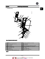
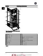
Page 8: ...Brake 81 82 and load sharing 88 89 terminals 5 Analog switches A53 A54 14 Line power input terminals 91 L1 92 L2 93 L3 6 Cable strain relief PE ground 15 USB connector 7 Decoupling plate 16 Serial bus terminal switch 8 Grounding clamp PE 17 Digital I O and 24 V power supply 9 Shielded cable grounding clamp and strain relief 18 Control cable cover plate Table 1 1 Introduction AF 600 FP Design and I...

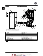
Page 9: ...PE 5 Analog I O connector 15 Cable strain relief PE ground 6 Cable strain relief PE ground 16 Brake terminal 81 82 7 USB connector 17 Load sharing terminal DC bus 88 89 8 Serial bus terminal switch 18 Motor output terminals 96 U 97 V 98 W 9 Analog switches A53 A54 19 Line power input terminals 91 L1 92 L2 93 L3 10 Relay 1 01 02 03 Table 1 2 Introduction AF 600 FP Design and Installation Guide 1 2 ...

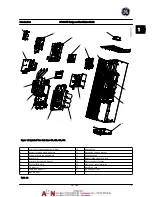
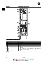
Page 10: ...3 Power card and mounting plate 12 Capacitor bank 4 Inrush card 13 Balance High frequency card 5 Inrush card mounting bracket 14 Motor output terminals 6 Top fan IP20 only 15 Line power input terminals 7 DC inductor 16 Gate drive card 8 SCR Diode modules 17 optional RFI filter 9 IGBT modules Table 1 3 Introduction AF 600 FP Design and Installation Guide DET 768A 1 3 1 1 ...

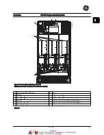
Page 11: ...S Fuse see 12 3 Fuse Tables for part number 106 104 105 7 AUX Fan 3 Line 100 101 102 103 R S T L1 L2 L1 L2 91 92 93 8 Fan Fuse see 12 3 Fuse Tables for part number L1 L2 L3 9 Mains ground 4 Load sharing 10 Motor DC DC U V W 88 89 96 97 98 T1 T2 T3 Table 1 4 Introduction AF 600 FP Design and Installation Guide 1 4 DET 768A 1 1 ...

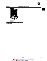
Page 12: ...Figure 1 5 Position of Ground Terminals IP21 NEMA Type 1 and IP54 NEMA Type 12 Introduction AF 600 FP Design and Installation Guide DET 768A 1 5 1 1 ...

Page 13: ... 2 Manual Motor Starters 7 SMPS Fuse See 12 3 Fuse Tables for part numbers 3 30 A Fuse Protected Power Terminals 8 Manual Motor Controller fuses 3 or 6 pieces See 12 3 Fuse Tables for part numbers 4 Line 9 Line Fuses unit sizes 61 and 62 3 pieces See 12 3 Fuse Tables for part numbers R S T 10 30 Amp Fuse Protected Power fuses L1 L2 L3 Table 1 5 Introduction AF 600 FP Design and Installation Guide ...

Page 14: ...External Temperature Monitoring 6 Motor 2 AUX Relay U V W 01 02 03 96 97 98 04 05 06 T1 T2 T3 4 AUX Fan 8 Fan Fuses See 12 3 Fuse Tables for part numbers 100 101 102 103 9 SMPS Fuses See 12 3 Fuse Tables for part numbers L1 L2 L1 L2 Table 1 6 Introduction AF 600 FP Design and Installation Guide DET 768A 1 7 1 1 ...

Page 15: ...m feedback such as changing temperature or pressure for controlling fan compressor or pump motors The adjustable frequency drive can also regulate the motor by responding to remote commands from external controllers In addition the adjustable frequency drive monitors the system and motor status issues warnings or alarms for fault conditions starts and stops the motor optimizes energy efficiency an...

Page 16: ...rent are monitored to provide efficient operation and control User interface and external commands are monitored and performed Status output and control can be provided Table 1 7 Adjustable Frequency Drive Internal Components Introduction AF 600 FP Design and Installation Guide DET 768A 1 9 1 1 ...

Page 17: ...Introduction AF 600 FP Design and Installation Guide 1 10 DET 768A 1 1 ...

Page 18: ...red to verify the proper equipment Ensure each of the following are rated for the same voltage Line power Adjustable frequency drive Motor Ensure that the adjustable frequency drive output current rating is equal to or greater than motor full load current for peak motor performance Motor size and adjustable frequency drive power must match for proper overload protection If adjustable frequency dri...

Page 19: ...omponents installed inside the enclosure The total required air flow must be calculated so that the appropriate fans can be selected Some enclosure manufacturers offer software for performing the calculations i e Rittal Therm software If the drive is the only heat generating component in the enclosure the minimum airflow required at an ambient temperature of 113 F 45 C for the 43 and 44 unit size ...

Page 20: ...f the unit to determine a safe lifting method Ensure that the lifting device is suitable for the task If necessary plan for a hoist crane or forklift with the appropriate rating to move the unit For lifting use hoist rings on the unit when provided Figure 2 6 Recommended Lifting Method 4X and 5X Unit Sizes WARNING The lifting bar must be able to handle the weight of the adjustable frequency drive ...

Page 21: ... the top section only of the backchannel cooling kits available for unit sizes 43 44 and 52 In addition to the enclosure an 8 in 200 mm vented pedestal is required The minimum enclosure depth is 19 7 in 500 mm 23 6 in 600 mm for unit size 52 and the minimum enclosure width is 23 6 in 600 mm 31 5 in 800 mm for unit size 52 The maximum depth and width are as required for the installation When using ...

Page 22: ...unit sizes 43 44 and 52 These kits are designed and tested to be used with IP00 Chassis drives in welded box construction enclosures with an environmental rating of NEMA 3R or NEMA 4 The NEMA 3R enclosure is a dust tight rain tight ice resistant outdoor enclosure The NEMA 4 enclosure is a dust tight and water tight enclosure This kit has been tested and complies with UL environ mental rating Type ...

Page 23: ...r These shields satisfy VBG 4 requirements NOTE For further information please consult GE 2 4 8 USB Extension Kit A USB extension cable can be installed into the door of unit size 6x adjustable frequency drives Ordering information Unit size 1x through 5x OPCUSB Unit size 6x OPCUSB6X 2 4 9 Installation of 4x or 5x Load Share Option The load share option can be installed on unit sizes 41 42 43 44 5...

Page 24: ...inals Wiring the AC line power to the adjustable frequency drive input terminals Connecting control and serial communication wiring After power has been applied checking input and motor power programming control terminals for their intended functions Figure 2 12 shows a basic electrical connection Figure 2 12 Basic Wiring Schematic Drawing Installation AF 600 FP Design and Installation Guide DET 7...

Page 25: ...nd Alarms for details on the trip function Because the motor wiring carries high frequency current it is important that wiring for line power motor power and control is run separately Use metallic conduit or separated shielded wire Failure to isolate power motor and control wiring could result in less than optimum equipment performance All adjustable frequency drives must be provided with short ci...

Page 26: ...0 mm2 Two separate ground wires both complying with the dimensioning rules See EN 60364 5 54 543 7 for further information Using RCDs Where residual current devices RCDs also known as ground leakage circuit breakers GLCBs are used comply with the following Use RCDs of type B only which are capable of detecting AC and DC currents Use RCDs with an inrush delay to prevent faults due to transient grou...

Page 27: ...the intermediate circuit and to reduce ground capacity currents in accordance with IEC 61800 3 2 5 4 1 External Fan Supply Unit Sizes 41 42 43 44 51 and 52 If the adjustable frequency drive is supplied by DC or if the fan must run independently of the power supply an external power supply can be applied The connection is made on the power card Terminal No Function 100 101 102 103 Auxiliary supply ...

Page 28: ... cable entry on adjustable frequency drive 2 5 7 Connector Conduit Entry Unit Sizes 41 42 and 51 Cables are connected through the connector plate from the bottom Remove the plate and plan where to place the entry for the connectors or conduits Prepare holes in the marked area on the drawing NOTE The connector plate must be fitted to the adjustable frequency drive to ensure the specified protection...

Page 29: ...is connected to a thermistor for PELV isolation optional thermistor control wiring must be reinforced double insulated A 24 V DC supply voltage is recommended 2 5 8 1 Access Remove access cover plate with a screw driver See Figure 2 26 Or remove front cover by loosening attaching screws See Figure 2 27 Figure 2 26 Control Wiring Access for IP20 Open chassis enclosures Installation AF 600 FP Design...

Page 30: ...pply voltage and a common for optional customer supplied 24 V DC voltage Connector 2 terminals 68 and 69 are for an RS 485 serial communications connection Connector 3 provides two analog inputs one analog output 10 V DC supply voltage and commons for the inputs and output Connector 4 is a USB port available for use with the adjustable frequency drive Also provided are two Form C relay outputs tha...

Page 31: ...l Communication 61 Integrated RC filter for cable shield ONLY for connecting the shield when experiencing EMC problems Terminal Description Digital Inputs Outputs Terminal Parameter Default Setting Description 68 O 3 RS 485 Interface A control card switch is provided for termination resistance 69 O 3 Relays 01 02 03 E 24 0 0 Alarm Form C relay output Usable for AC or DC voltage and resistive or in...

Page 32: ...munication This terminal is grounded via an internal RC link Use twisted pair cables to reduce interference between conductors The recommended method is shown below Figure 2 34 1 Min 0 025 in2 16 mm2 2 Equalizing cable Table 2 6 Alternatively the connection to terminal 61 can be omitted Figure 2 35 1 Min 0 025 in2 16 mm2 2 Equalizing cable Table 2 7 2 5 8 5 Control Terminal Functions Adjustable fr...

Page 33: ...gment Repeaters divide network segments Note that each repeater functions as a node within the segment in which it is installed Each node connected within a given network must have a unique node address across all segments Terminate each segment at both ends using either the termination switch S801 of the adjustable frequency drives or a biased termination resistor network Always use shielded twis...

Page 34: ...djustable frequency drive disconnect switches for input power isolation 2 Verify that there is no voltage on input terminals L1 91 L2 92 and L3 93 phase to phase and phase to ground 3 Verify that there is no voltage on output terminals 96 U 97 V and 98 W phase to phase and phase to ground 4 Confirm continuity of the motor by measuring ohm values on U V 96 97 V W 97 98 and W U 98 96 5 Check for pro...

Page 35: ...nce is adequate to ensure proper airflow for cooling EMC considerations Check for proper installation regarding electromagnetic compatibility Environmental consider ations See equipment label for the maximum ambient operating temperature limits Humidity levels must be 5 95 non condensing Fusing and circuit breakers Check for proper fusing or circuit breakers Check that all fuses are inserted firml...

Page 36: ...mum motor speeds Enter data in accordance with the following procedure The recommended parameter settings are intended for startup and checkout purposes Application settings may vary See 4 User Interface for detailed instructions on entering data through the keypad Enter data with power ON but before operating the adjustable frequency drive 1 Press Quick Menu on the keypad 2 Use the navigation key...

Page 37: ...y two of the three motor cables on the motor or adjustable frequency drive side of the connection 3 6 Local Control Test CAUTION MOTOR START Ensure that the motor system and any attached equipment are ready for start It is the responsibility of the user to ensure safe operation under any condition Failure to ensure that the motor system and any attached equipment are ready for start could result i...

Page 38: ...mpleted CAUTION MOTOR START Ensure that the motor system and any attached equipment is ready for start It is the responsibility of the user to ensure safe operation under any condition Failure to do so could result in personal injury or equipment damage 1 Press Auto 2 Ensure that external control functions are properly wired to the adjustable frequency drive and all programming completed 3 Apply a...

Page 39: ...Start Up and Functional Tes AF 600 FP Design and Installation Guide 3 6 DET 768A 3 3 ...

Page 40: ...nctions Manually reset the adjustable frequency drive after a fault when auto reset is inactive NOTE The display contrast can be adjusted by pressing Status and key 4 1 1 Keypad Layout The keypad is divided into four functional groups see Figure 4 1 Figure 4 1 keypad a Display area b Display menu keys for changing the display to show status options programming or error message history c Navigation...

Page 41: ... Function Status Shows operational information In auto mode press to toggle between status readout displays Press repeatedly to scroll through each status display Press Status plus or to adjust the display brightness The symbol in the upper right corner of the display shows the direction of motor rotation and which set up is active This is not programmable Quick Menu Allows access to programming p...

Page 42: ...yed Table 4 4 4 1 5 Operation Keys Operation keys are found at the bottom of the keypad Figure 4 5 Key Function Hand Starts the adjustable frequency drive in local control Use the navigation keys to control adjustable frequency drive speed An external stop signal by control input or serial communication overrides the local hand on Off Stops the motor but does not remove power to the adjustable fre...

Page 43: ...ncy drive parameter settings back to default values is done by initialization of the adjustable frequency drive Initialization can be through H 03 Restore Factory Settings or manually Initialization using H 03 Restore Factory Settings does not change adjustable frequency drive data such as operating hours serial communication selections personal menu settings fault log alarm log and other monitori...

Page 44: ...sy guidelines for getting most systems up and running The main menu accesses all parameters and allows for advanced adjustable frequency drive applications 5 2 Programming Example Here is an example for programming the adjustable frequency drive for a common application in open loop using the quick menu This procedure programs the adjustable frequency drive to receive a 0 10 V DC analog control si...

Page 45: ...0 V This sets the minimum input signal at 0 V Figure 5 4 5 AN 11 Terminal 53 High Voltage Set maximum external voltage reference on Terminal 53 at 10 V This sets the maximum input signal at 10 V Figure 5 5 6 AN 14 Terminal 53 Low Ref Feedb Value Set minimum speed reference on Terminal 53 at 20 Hz This tells the adjustable frequency drive that the minimum voltage received on Terminal 53 0 V equals ...

Page 46: ...Figure 5 8 Wiring Example for External Device Providing 0 10 V Control Signal Adjustable Frequency Drive Left External Device Right 5 3 Control Terminal Programming Examples Control terminals can be programmed Each terminal has specified functions it is capable of performing Parameters associated with the terminal enable the function See Table 2 4 for control terminal parameter number and default ...

Page 47: ...national default parameter value North American default parameter value F 03 Max Output Frequency 1 132 Hz 120 Hz H 73 Warning Speed High 1500 RPM 1800 RPM E 03 Terminal 27 Digital Input Coast inverse External interlock E 24 Function Relay No operation No alarm AN 15 Terminal 53 High Ref Feedb Value 50 60 AN 50 Terminal 42 Output No operation Speed 4 20 mA H 04 Auto Reset Times Manual reset Infini...

Page 48: ... other features See the keypad display to view detailed parameter programming and setting options Press Info in any menu location to view additional details for that function Press and hold Main Menu to enter a parameter number for direct access to that parameter Details for common application set ups are provided in 6 Application Set up Examples 5 5 1 Quick Menu Structure Quick Start K 01 Languag...

Page 49: ...ted Voltage F 5 Extended References E 11 Decel Time 2 K 14 Readout Edit Set ups Channel K 60 Main Menu Password F 07 Accel Time 1 F 52 Minimum Reference E 2 Digital Outputs K 2 Keypad Display K 61 Access to Main Menu w o Password F 08 Decel Time 1 F 53 Maximum Reference E 20 Terminal 27 Digital Output K 20 Display Line 1 1 Small K 65 Quick Menu Password F 1 Fundamental 1 F 54 Reference Function E ...

Page 50: ...69 Pulse Filter Time Constant 33 C 21 Jog Speed RPM H 04 Auto Reset Times H 75 Warning Reference High AN 22 Terminal 54 Low Current E 7 Pulse Output C 22 Jog Accel Decel Time H 05 Auto Reset Reset Interval H 76 Warning Feedback Low AN 23 Terminal 54 High Current E 70 Terminal 27 Pulse Output Variable C 3 Frequency Setting 2 and 3 H 06 Fan Operation H 77 Warning Feedback High AN 24 Terminal 54 Low ...

Page 51: ...dback 1 AN 52 Terminal 42 Output Max Scale SP 29 Service Code O Options Comms O 4 Drive MC protocol set O 95 Bus Feedback 2 AN 53 Terminal 42 Output Bus Control SP 3 Current Limit Ctrl O 0 General Settings O 40 Telegram Selection O 96 Bus Feedback 3 AN 54 Terminal 42 Output Timeout Preset SP 30 Current Lim Ctrl Proportional Gain O 01 Control Site O 42 PCD write configuration AO Analog I O Option A...

Page 52: ...nk Parameters EN 95 Broadcast Storm Filter DN 11 Process Data Config Write AO 35 Term X42 5 High Ref Feedb Value PB 53 Profibus Warning Word EN 10 Link Status EN 98 Interface Counters DN 12 Process Data Config Read AO 36 Term X42 5 Filter Time Constant PB 63 Actual Baud Rate EN 11 Link Duration EN 99 Media Counters DN 13 Warning Parameter AO 37 Term X42 5 Live Zero PB 70 Edit Set up EN 12 Auto Neg...

Page 53: ...o DR 36 Drive Nominal Current DR 73 Counter B LG 31 Analog Input X42 3 ID 13 Trending Mode ID 63 Option Serial No DR 37 Drive Max Current DR 75 Analog In X30 11 LG 32 Analog Input X42 5 ID 14 Samples Before Trigger ID 9 Parameter Info DR 38 Logic Controller State DR 76 Analog In X30 12 LG 33 Analog Out X42 7 V ID 2 Historic Log ID 92 Defined Parameters DR 39 Control Card Temp DR 77 Analog Out X30 ...

Page 54: ...Minimum Sleep Time AP 86 Speed at Design Point Hz FB 34 Missing Motor Coefficient 4 T 64 Timed Period Stop CL 3 Feedback Adv Conv AP 42 Wake up Speed RPM AP 87 Pressure at No Flow Speed T Timed Functions T 65 Minimum Bin Value CL 30 Refrigerant AP 43 Wake up Speed Hz AP 88 Pressure at Rated Speed T 0 Timed Actions T 66 Reset Continuous Bin Data CL 31 User Defined Refrigerant A1 AP 44 Wake up Ref F...

Page 55: ...ters B 16 AC brake Max Current XC 00 Closed Loop Type XC 41 Ext 2 Proportional Gain PC 24 SBW Destaging Delay PC 9 Service B 17 Over voltage Control XC 01 PID Performance XC 42 Ext 2 Integral Time PC 25 OBW Time PC 90 Pump Interlock XC 02 PID Output Change XC 43 Ext 2 Differentation Time PC 26 Destage At No Flow PC 91 Manual Alternation XC 03 Minimum Feedback Level XC 44 Ext 2 Dif Gain Limit PC 27...

Page 56: ...the keypad Additionally all adjustable frequency drive programming can be done off line and simply downloaded to the adjustable frequency drive Or the entire adjustable frequency drive profile can be loaded onto the PC for backup storage or analysis The USB connector or RS 485 terminal is available for connecting to the adjustable frequency drive For more details go to www geelectrical com drives ...

Page 57: ...About Programming AF 600 FP Design and Installation Guide 5 14 DET 768A 5 5 ...

Page 58: ...cation Examples Parameters Function Setting AN 10 Terminal 53 Low Voltage 0 07 V AN 11 Terminal 53 High Voltage 10 V AN 14 Terminal 53 Low Ref Feedb Value 0 RPM AN 15 Terminal 53 High Ref Feedb Value 1500 RPM Default Value Notes comments Table 6 1 Analog Speed Reference Voltage Parameters Function Setting AN 12 Terminal 53 Low Current 4 mA AN 13 Terminal 53 High Current 20 mA AN 14 Terminal 53 Low...

Page 59: ...g E 05 Terminal 32 Digital Input 16 Preset ref bit 0 E 06 Terminal 33 Digital Input 17 Preset ref bit 1 C 05 Multi step Frequency 1 8 Preset ref 0 Preset ref 1 Preset ref 2 Preset ref 3 25 50 75 100 Default Value Notes comments Table 6 4 Start Stop with Reversing and Four Preset Speeds Parameters Function Setting E 02 Terminal 19 Digital Input 1 Reset Default Value Notes comments Table 6 5 Externa...

Page 60: ...al Input 19 Freeze Reference E 04 Terminal 29 Digital Input 21 Speed Up E 05 Terminal 32 Digital Input 22 Slow Default Value Notes comments Table 6 7 Speed Up Down Start 18 Freeze ref 27 Speed up 29 Speed down 32 Speed Reference 130BB840 10 Figure 6 3 Parameters Function Setting O 30 Protocol Modbus O 31 Address 1 O 32 Drive Port Baud Rate 9600 Default Value Notes comments Select protocol address ...

Page 61: ...C 52 Logic Controller Action 32 Set digital out A low E 24 Function Relay 80 Logic Controller digital output A Default Value Notes comments If the limit in the feedback monitor is exceeded Warning 90 will be issued The monitors Warning 90 and in the case that Warning 90 becomes TRUE then Relay 1 is triggered External equipment may then indicate that service may be required If the feedback error go...

Page 62: ...etting 1 to Analog input 53 hand mode 6 Copy set up 1 to set up 2 Set K 51 Set up Copy to 2 Copy to set up 2 Now set up 1 and 2 are identical 7 If you need to be able to change between hand and auto mode while the motor is running you will have to link the 2 set ups together Set K 12 This Set up Linked to to 2 set up 2 8 Change to set up 2 by setting input 27 ON if parameter K 11 is 9 or by settin...

Page 63: ...ectricity however is reduced by 50 If the system in question only needs to be able to supply a flow corresponding to 100 a few days each year while the average is below 80 of the rated flow for the remainder of the year the amount of energy saved is even greater than 50 Figure 6 6 describes the dependency of flow pressure and power consumption on RPM Figure 6 6 The laws of proportionality Flow Q1 ...

Page 64: ...l 6 3 5 Cos φ Compensation Generally speaking the AF 600 FP has a cos φ of 1 and provides power factor correction for the cos φ of the motor which means that there is no need to make allowance for the cos φ of the motor when sizing the power factor correction unit 6 3 6 Using an Adjustable Frequency Drive Saves Money The example on the following page shows that a lot of extra equipment is not requ...

Page 65: ... a fan system made in the traditional way Figure 6 7 D D C Direct Digital Control V A V Variable Air Volume Sensor P Pressure E M S Energy Management System Sensor T Temperature Application Set up Examples AF 600 FP Design and Installation Guide 6 8 DET 768A 6 6 ...

Page 66: ... shows a fan system controlled by adjustable frequency drives Figure 6 8 6 3 9 Application Examples The next few pages give typical examples of applications within HVAC Application Set up Examples AF 600 FP Design and Installation Guide DET 768A 6 9 6 6 ...

Page 67: ...ergy and reduces the complexity of the installation Instead of creating an artificial pressure drop or causing a decrease in fan efficiency the adjustable frequency drive decreases the speed of the fan to provide the flow and pressure required by the system Centrifugal devices such as fans behave according to the centrifugal laws This means the fans decrease the pressure and flow they produce as t...

Page 68: ...lly used in air conditioning systems as the outside temperature varies and the number of people in the controlled zone changes different cooling requirements arise As the temperature decreases below the setpoint the supply fan can decrease its speed The return fan modulates to maintain a static pressure setpoint By decreasing the air flow energy used to heat or cool the fresh air is also reduced a...

Page 69: ...eed required to maintain the condenser water temperature The adjustable frequency drives can also be used to turn the fan on and off as needed Several features of the GE dedicated adjustable frequency drive can be utilized to improve the performance of your cooling tower fans application As the cooling tower fans drop below a certain speed the effect the fan has on cooling the water becomes insign...

Page 70: ... efficient than air cooled chillers 6 3 17 The AF 600 FP Solution Adjustable frequency drives can be added to condenser water pumps instead of balancing the pumps with a throttling valve or trimming the pump impeller Using an adjustable frequency drive instead of a throttling valve simply saves the energy that would have been absorbed by the valve This can amount to savings of 15 20 or more Trimmi...

Page 71: ...ting expenses Two control methods are common The first method uses a flow meter Because the desired flow rate is known and constant a flow meter installed at the discharge of each chiller can be used to control the pump directly Using the built in PID controller the adjustable frequency drive will always maintain the appropriate flow rate even compensating for the changing resistance in the primar...

Page 72: ...s and eases system control problems the true energy savings and control potential is realized by adding adjustable frequency drives With the proper sensor location the addition of adjustable frequency drives allows the pumps to vary their speed to follow the system curve instead of the pump curve This results in the elimination of wasted energy and eliminates most of the over pressurization to whi...

Page 73: ...Application Set up Examples AF 600 FP Design and Installation Guide 6 16 DET 768A 6 6 ...

Page 74: ...re as well as on the motor enclosure This is best done by using integrated shield clamps so as to avoid twisted shield ends pigtails These increase the shield impedance at higher frequencies which reduces the shield effect and increases the leakage current I4 If a shielded cable is used for networknetwork relay control cable signal interface and brake the shield must be mounted on the enclosure at...

Page 75: ...to be installed and commissioned by a professional Class A Group 1 C3 adjustable frequency drives installed in the second environment industrial with a supply voltage lower than 1000 V Class A Group 2 C4 Adjustable frequency drives installed in the second environment with a supply voltage equal to or above 1000 V or rated current equal to or above 400 A or intended for use in complex systems No li...

Page 76: ...on 7 2 Immunity Requirements The immunity requirements for adjustable frequency drives depend on the environment where they are installed The requirements for the industrial environment are higher than the requirements for the home and office environment All GE adjustable frequency drives comply with the requirements for the industrial environment and consequently comply also with the lower requir...

Page 77: ...ity requirements for adjustable frequency drives depend on the environment where they are installed The requirements for the industrial environment are higher than the requirements for the home and office environment All GE adjustable frequency drives comply with the requirements for the industrial environment and consequently comply also with the lower requirements for home and office environment...

Page 78: ...Ω1 10 VRMS External 24 V DC 2 kV CM 0 5 kV 2 Ω DM 1 kV 12 Ω CM 10 VRMS Enclosure 8 kV AD 6 kV CD 10 V m AD Air Discharge CD Contact Discharge CM Common mode DM Differential mode 1 Injection on cable shield Table 7 5 EMC Immunity Form 7 3 General Aspects of Harmonics Emission An adjustable frequency drive takes up a non sinusoidal current from the line power which increases the input current IRMS A...

Page 79: ...y to a supply with a short circuit power Ssc greater than or equal to that specified above Other power sizes can be connected to the public supply network by consultation with the distribution network operator Compliance with various system level guidelines The harmonic current data in the table are given in accordance with IEC EN61000 3 12 with reference to the Power Drive Systems product standar...

Page 80: ...e The adjustable frequency drive constantly checks for critical levels of internal temperature load current high voltage on the intermediate circuit and low motor speeds As a response to a critical level the adjustable frequency drive can adjust the switching frequency and or change the switching pattern in order to ensure the performance of the adjustable frequency drive The capability to automat...

Page 81: ...drive Typical torque at VT load Max torque with forced cooling Max torque Table 7 8 Note 1 Oversynchronous speed operation will result in the available motor torque decreasing inversely proportional to the increase in speed This must be considered during the design phase to avoid overloading the motor 7 6 Motor Insulation For motor cable lengths than the maximum cable length listed in the General ...

Page 82: ...onnection between the motor and the adjustable frequency drive for instance by shielded cable which has a 360 connection in the motor and the adjustable frequency drive Make sure that the impedance from adjustable frequency drive to building ground is lower that the grounding impedance of the machine This can be difficult for pumps Make a direct ground connection between the motor and load motor 3...

Page 83: ...Installation Consideration AF 600 FP Design and Installation Guide 7 10 DET 768A 7 7 ...

Page 84: ... pressed Auto The adjustable frequency drive is controlled from the control terminals and or the serial communication Hand The navigation keys on the keypad control the adjustable frequency drive Stop commands reset reversing DC brake and other signals applied to the control terminals can override local control Table 8 1 Reference Site Remote The speed reference is given from external signals seri...

Page 85: ...e Reference was chosen as a function for a digital input The corresponding terminal is active The adjustable frequency drive saves the actual reference Changing the reference is now only possible via terminal functions Speed Up and Slow Jog request A jog command has been given but until a run permissive signal is received via a digital input the motor is stopped Jogging The motor is running as pro...

Page 86: ...stable frequency drive starts the motor with a start signal from a digital input or serial communi cation Start delay In F 24 Holding Time a delay starting time was set A start command is activated and the motor will start after the start delay time expires Start fwd rev Start forward and start reverse were selected as functions for two different digital inputs The motor starts in forward or rever...

Page 87: ...Status Messages AF 600 FP Design and Installation Guide 8 4 DET 768A 8 8 ...

Page 88: ... system damage The motor will coast to a stop The adjustable frequency drive logic will continue to operate and monitor the adjustable frequency drive status After the fault condition is remedied the adjustable frequency drive can be reset It will then be ready to start operation again A trip can be reset in any of 4 ways Press Reset on the keypad Digital reset input command Serial communication r...

Page 89: ...link voltage high X 6 DC link voltage low X 7 DC overvoltage X X 8 DC undervoltage X X 9 Inverter overloaded X X 10 Motor electronic overload X X F 10 Electronic Overload 11 Motor thermistor over temperature X X F 10 Electronic Overload 12 Torque limit X X 13 Overcurrent X X X 14 Ground fault X X X 15 Hardware mismatch X X 16 Short circuit X X 17 Control word timeout X X O 04 Control Word Timeout ...

Page 90: ...8 V supply low X X 49 Speed limit X X H 36 Trip Speed Low RPM 50 Auto tune calibration failed X 51 Auto tune check Unom and Inom X 52 Auto tune low Inom X 53 Auto tune motor too big X 54 Auto tune motor too small X 55 Auto tune Parameter out of range X 56 Auto tune interrupted by user X 57 Auto tune timeout X 58 Auto tune internal fault X X 59 Current limit X 60 External Interlock X 62 Output Freq...

Page 91: ...ections on all the analog input terminals Control card terminals 53 and 54 for signals terminal 55 common OPCGPIO terminals 11 and 12 for signals terminal 10 common OPCAIO terminals 1 3 5 for signals terminals 2 4 6 common Check that the adjustable frequency drive programming and switch settings match the analog signal type Perform Input Terminal Signal Test WARNING ALARM 4 Mains phase loss A phas...

Page 92: ... If an external fan is in use check in F 11 Motor External Fan that it is selected Running Auto tune in P 04 Auto Tune tunes the adjustable frequency drive to the motor more accurately and reduces thermal loading WARNING ALARM 11 Motor thermistor over temp Check whether the thermistor is disconnected Select whether the adjustable frequency drive issues a warning or an alarm in F 10 Electronic Over...

Page 93: ... the serial communication cable Increase O 03 Control Word Timeout Time Check the operation of the communication equipment Verify a proper installation based on EMC requirements ALARM 18 Start failed The speed has not been able to exceed AP 70 Compressor Start Max Speed RPM during start within the allowed time set in AP 72 Compressor Start Max Time to Trip This may be caused by a blocked motor WAR...

Page 94: ...Text 1299 Option SW in slot A is too old 1300 Option SW in slot B is too old 1302 Option SW in slot C1 is too old 1315 Option SW in slot A is not supported not allowed 1316 Option SW in slot B is not supported not allowed 1318 Option SW in slot C1 is not supported not allowed 1379 2819 Internal fault Contact your GE supplier or GE Service Department 2820 Keypad stack overflow 2821 Serial port over...

Page 95: ... 56 ALARM Auto tune interrupted by user The user has interrupted the Auto tune ALARM 57 Auto tune internal fault Try to restart Auto tune again Repeated restarts can overheat the motor ALARM 58 Auto Tune internal fault Contact your GE supplier WARNING 59 Current limit The current is higher than the value in F 43 Current Limit Ensure that Motor data in parameters P 02 P 03 P 06 P 07 F 04 and F 05 a...

Page 96: ...wer to the unit to remove the warning See the fire mode data in the alarm log WARNING 202 Fire mode limits exceeded While operating in fire mode one or more alarm conditions have been ignored which would normally trip the unit Operating in this condition voids unit warranty Cycle power to the unit to remove the warning See the fire mode data in the alarm log WARNING 203 Missing motor With an adjus...

Page 97: ...Warnings and Alarms AF 600 FP Design and Installation Guide 9 10 DET 768A 9 9 ...

Page 98: ...10 V supply for terminal 50 to 55 Wire the terminals properly Wrong contrast setting Press Status to adjust the contrast Display keypad is defective Test using a different keypad Replace the faulty keypad or connection cable Internal voltage supply fault or SMPS is defective Contact supplier Intermittent display Overloaded power supply SMPS due to improper control wiring or a fault within the adju...

Page 99: ...tor running in wrong direction Motor rotation limit Check that H 08 Reverse Lock is programmed correctly Program correct settings Active reversing signal Check if a reversing command is programmed for the terminal in parameter group E 0 Digital inputs Deactivate reversing signal Wrong motor phase connection See 3 5 Check Motor Rotation in this manual Motor is not reaching maximum speed Frequency l...

Page 100: ...ustable frequency drive one position A to B B to C C to A If imbalance leg stays on same input terminal it is a problem with the unit Contact the supplier Motor current imbalance greater than 3 Problem with motor or motor wiring Rotate output motor leads one position U to V V to W W to U If imbalanced leg follows the wire the problem is in the motor or motor wiring Check motor and motor wiring Pro...

Page 101: ...Basic Troubleshooting AF 600 FP Design and Installation Guide 10 4 DET 768A 10 0 ...

Page 102: ...0 HP 45 55 kW 60 75 HP 45 55 kW 60 75 HP IP20 10 89 50 1 10 89 50 1 10 89 50 1 10 89 50 1 18 5 30 kW 25 40 HP 37 55 kW 50 75 HP 37 55 kW 50 75 HP IP55 or IP66 90 3 0 90 3 0 90 3 0 90 3 0 37 45 kW 50 60 HP 75 90 kW 100 125 HP 75 90 kW 100 125 HP IP20 14 124 150 300 mcm 14 124 150 300 mcm 14 124 95 4 0 14 124 95 4 0 37 45 kW 50 60 HP 75 90 kW 100 125 HP 75 90 kW 100 125 HP 37 90 kW 50 125 HP IP55 or...

Page 103: ...Terminal and Applicable Wir AF 600 FP Design and Installation Guide 11 2 DET 768A 11 1 ...

Page 104: ...P20 Chassis IP 21 Type 1 IP54 IP55 Type 12 IP66 Type 4X 440 V 440 V 1 0 75 2 4 2 12 7 2 7 0 96 12 15 15 2 1 5 4 1 3 4 3 7 0 97 3 2 2 5 6 4 8 5 0 97 5 4 0 10 8 2 9 0 97 12 15 15 7 5 5 5 13 11 11 7 0 97 13 10 7 5 16 14 5 14 4 0 97 15 11 24 21 22 0 98 23 21 21 20 15 32 27 29 0 98 25 18 37 5 34 34 0 98 30 22 44 40 40 0 98 24 22 22 40 30 61 52 55 0 98 50 37 73 65 66 0 98 31 31 60 45 90 80 82 0 98 33 75...

Page 105: ... 1 5 2 9 2 7 2 7 0 97 3 2 2 4 1 3 9 3 9 0 97 5 4 0 6 4 6 1 6 1 0 97 7 5 5 5 9 5 9 9 0 97 10 7 5 11 5 11 11 0 97 15 11 19 18 18 0 98 23 21 21 20 15 23 22 22 0 98 25 18 28 27 27 0 98 30 22 36 34 34 0 98 24 22 22 40 30 43 41 41 0 98 50 37 54 52 52 0 98 60 45 65 62 62 0 98 33 31 31 75 55 87 83 83 0 98 100 75 105 100 100 0 98 34 32 32 125 90 137 131 131 0 98 Table 12 3 525 600 V 525 690 V hp kW A Input...

Page 106: ... 352 0 98 550 400 418 400 400 0 98 600 450 470 450 434 0 98 52 51 51 650 500 523 500 482 0 98 750 560 596 570 549 0 98 900 630 630 630 607 0 98 1000 710 763 730 730 0 98 61 63 61 63 1200 800 889 850 850 0 98 1250 900 988 945 945 0 98 1350 1000 1108 1060 1060 0 98 62 64 62 64 1600 1200 1317 1260 1260 0 98 1900 1400 1479 1415 1415 0 98 Table 12 4 525 690 V 12 1 2 Dimensions Unit Size 1x Figure 12 1 ...
Page 107: ...Figure 12 2 Unit Size 13 Figure 12 3 Unit Size 15 Specifications AF 600 FP Design and Installation Guide 12 4 DET 768A 12 2 ...

Page 108: ...12 1 3 Dimensions Unit Size 2x Figure 12 4 Unit Size 21 Figure 12 5 Unit Size 22 Specifications AF 600 FP Design and Installation Guide DET 768A 12 5 12 12 ...

Page 109: ...Figure 12 6 Unit Size 23 Figure 12 7 Unit Size 24 Specifications AF 600 FP Design and Installation Guide 12 6 DET 768A 12 2 ...

Page 110: ...12 1 4 Dimensions Unit Size 3x Figure 12 8 Unit Size 31 Figure 12 9 Unit Size 32 Specifications AF 600 FP Design and Installation Guide DET 768A 12 7 12 12 ...

Page 111: ...Figure 12 10 Unit Size 33 Figure 12 11 Unit Size 34 Specifications AF 600 FP Design and Installation Guide 12 8 DET 768A 12 2 ...

Page 112: ...12 1 5 Dimensions Unit Size 4x Figure 12 12 Unit Size 41 Floor or Cabinet Mount Specifications AF 600 FP Design and Installation Guide DET 768A 12 9 12 12 ...

Page 113: ...Figure 12 13 Unit Size 42 Floor or Cabinet Mount Specifications AF 600 FP Design and Installation Guide 12 10 DET 768A 12 2 ...

Page 114: ...1099 Min 225 Exhaust Min 225 Inlet 1327 375 1280 765 m3 hr 255 m3 hr 408 130BD040 10 Drives shown with optional disconnect switch Figure 12 15 Unit Size 44 Cabinet Mount Specifications AF 600 FP Design and Installation Guide DET 768A 12 11 12 12 ...

Page 115: ...ower dependent Torque characteristics Starting torque Constant torque maximum 110 for 1 min Starting torque maximum 135 up to 0 5 s Overload torque Constant torque maximum 110 for 1 min Percentage relates to AF 600 FP Drive s nominal torque Cable lengths and cross sections for control cables Max motor cable length shielded 500 ft 150 m Max motor cable length non shielded 1000 ft 300 m Maximum cros...

Page 116: ...6 Pulse inputs Programmable pulse inputs 2 Terminal number pulse 29 33 Max frequency at terminal 29 33 110 kHz push pull driven Max frequency at terminal 29 33 5 kHz open collector Min frequency at terminal 29 33 4 Hz Voltage level see 12 2 1 Digital Inputs Maximum voltage on input 28 V DC Input resistance Ri approx 4 kΩ Pulse input accuracy 0 1 1 kHz Max error 0 1 of full scale Analog output Numb...

Page 117: ... relay outputs 2 Relay 01 Terminal number 1 3 break 1 2 make Max terminal load AC 1 1 on 1 3 NC 1 2 NO Resistive load 240 V AC 2 A Max terminal load AC 15 1 Inductive load cosφ 0 4 240 V AC 0 2 A Max terminal load DC 1 1 on 1 2 NO 1 3 NC Resistive load 60 V DC 1 A Max terminal load DC 13 1 Inductive load 24 V DC 0 1 A Relay 02 Terminal number 4 6 break 4 5 make Max terminal load AC 1 1 on 4 5 NO R...

Page 118: ...ons Minimum ambient temperature during full scale operation 32 F 0 C Minimum ambient temperature at reduced performance 14 F 10 C Temperature during storage transport 13 149 158 F 25 65 70 C Maximum altitude above sea level without derating 3 300 ft 1 000 m Maximum altitude above sea level with derating 10 000 ft 3 000 m Derating for high altitude see section on special conditions in the Design Gu...

Page 119: ...ecommends using the fuses circuit breakers mentioned below to protect service personnel and property in case of component breakdown in the adjustable frequency drive Overcurrent protection The adjustable frequency drive provides overload protection to limit threats to human life property damage and to avoid fire hazard due to overheating of the cables in the installation The adjustable frequency d...

Page 120: ...0 gG 125 18 5 25 22 30 gG 125 gG 150 30 40 aR 160 aR 160 37 50 aR 200 aR 200 45 60 aR 250 aR 250 Table 12 5 200 240 V IP20 Open Chassis AF 600 3 phase Recommended fuse size Recommended max fuse kW HP 0 75 1 gG 20 gG 32 1 5 2 2 2 3 3 7 5 5 5 7 5 gG 63 gG 80 7 5 10 11 15 15 20 gG 80 gG 100 18 5 25 gG 125 gG 160 22 30 30 40 aR 160 aR 160 37 50 aR 200 aR 200 45 60 aR 250 aR 250 Table 12 6 200 240 V IP...

Page 121: ...500 1000 1350 Table 12 8 380 480 V IP55 Nema 12 and IP66 Nema 4X AF 600 3 phase Recommended fuse size Recommended max fuse kW HP 0 75 1 gG 10 gG 25 1 5 2 2 2 3 3 7 5 5 5 7 5 gG 16 gG 32 7 5 10 11 15 gG 35 gG 63 15 20 18 5 25 22 30 gG 63 gG 125 30 40 37 50 45 60 gG 100 gG 150 55 75 75 100 aR 250 aR 250 90 125 Table 12 9 525 600 V IP20 Open Chassis AF 600 3 phase Recommended fuse size Recommended ma...

Page 122: ...50 aR 250 132 200 aR 315 aR 315 160 250 aR 350 aR 350 200 300 250 350 aR 400 aR 400 315 450 aR 500 aR 500 400 550 aR 550 aR 550 450 600 aR 700 aR 700 500 650 560 750 aR 900 aR 900 630 900 710 1000 aR 1600 aR 1600 800 1150 900 1250 1000 1350 1200 1600 aR 2000 aR 2000 1400 1900 aR 2500 aR 2500 Table 12 11 525 690 V IP21 Nema 1 and IP55 Nema 12 Specifications AF 600 FP Design and Installation Guide D...

Page 123: ...0 KS 50 JJN 50 5 5 7 5 11 15 KTN R 60 JKS 60 JJN 60 7 5 10 15 20 KTN R 80 JKS 80 JJN 80 18 5 22 25 30 KTN R 125 JKS 125 JJN 125 15 20 30 40 KTN R 150 JKS 150 JJN 150 23 30 37 50 KTN R 200 JKS 200 JJN 200 45 60 KTN R 250 JKS 250 JJN 250 Table 12 12 200 240 V Recommended max fuse AF 600 1 phase Power AF 600 3 phase Power SIBA Littel fuse Ferraz Shawmut Ferraz Shawmut kW HP kW HP Type RK1 Type RK1 Ty...

Page 124: ... drives 4 A50X fuses from FERRAZ SHAWMUT may substitute A25X for 240 V adjustable frequency drives Recommended max fuse AF 600 1 phase AF 600 3 phase Bussmann Bussmann Bussmann Bussmann Bussmann Bussmann kW HP kW HP Type RK1 Type J Type T Type CC Type CC Type CC 0 75 1 KTS R 6 JKS 6 JJS 6 FNQ R 6 KTK R 6 LP CC 6 1 5 2 2 2 3 KTS R 10 JKS 10 JJS 10 FNQ R 10 KTK R 10 LP CC 10 3 7 5 KTS R 20 JKS 20 JJ...

Page 125: ... KLS R 150 A6K 150 R 37 50 75 100 2028220 200 KLS R 200 A6K 200 R 90 125 2028220 250 KLS R 250 A6K 250 R Table 12 16 380 480 V 125 HP and below Recommended max fuse AF 600 1 phase AF 600 3 phase Bussmann Ferraz Shawmut Ferraz Shawmut Littel fuse kW HP kW HP Type JFHR2 Type J Type JFHR21 Type JFHR2 0 75 1 FWH 6 HSJ 6 1 5 2 2 2 3 FWH 10 HSJ 10 3 7 5 FWH 20 HSJ 20 5 5 7 5 FWH 25 HSJ 25 7 5 10 FWH 30 ...

Page 126: ...Ferraz Shawmut Ferraz Shawmut kW HP Type RK1 Type RK1 Type RK1 Type J 0 75 1 5017906 005 KLS R 005 A6K 5 R HSJ 6 1 5 2 2 2 3 5017906 010 KLS R 010 A6K 10 R HSJ 10 3 7 5 5017906 020 KLS R 020 A6K 20 R HSJ 20 5 5 7 5 5017906 025 KLS R 025 A6K 25 R HSJ 25 7 5 10 5017906 030 KLS R 030 A6K 30 R HSJ 30 11 15 15 20 5014006 040 KLS R 035 A6K 35 R HSJ 35 18 5 25 5014006 050 KLS R 045 A6K 45 R HSJ 45 22 30 ...

Page 127: ...2 20 525 690 IP21 Nema 1 and IP55 Nema 12 Recommended max fuse AF 600 Bussmann PN Bussmann PN Siba PN Littlefuse PN Ferraz Shawmut PN Ferraz Shawmut PN kW HP Type JFHR2 Type JFHR2 Type JFHR2 Type JFHR2 Type JFHR2 110 150 170M3017 FWH 300 20 610 31 315 L50 S 300 A50 P 300 6 9URD31D08A0315 132 7 87 200 170M3018 FWH 350 20 610 31 350 L50 S 350 A50 P 350 6 9URD31D08A0350 160 250 170M4012 FWH 400 20 61...

Page 128: ...08A0700 560 750 170M6013 20 610 32 700 6 9URD31D08A0700 630 900 170M6013 22 610 32 900 6 9URD33D08A0900 710 1000 170M7081 22 610 32 900 6 9URD33D08A0900 800 1150 170M7081 900 1250 170M7081 1000 1350 170M7081 1200 1600 170M7082 1400 1900 170M7083 Table 12 23 525 690 V above 125 HP AF 600 Bussmann PN Rating Alternate Siba PN kW HP 710 1000 170M8611 1100 A 1000 V 20 781 32 1000 800 1150 170M8611 1100...

Page 129: ...on operation or maintenance Should further information be desired or should particular problems arise which are not covered sufficiently for the purchaser s purposes the matter should be referred to the GE company AF 600 FP is a trademark of the General Electric Company GE 41 Woodford Avenue Plainville CT 06062 www geelectrical com drives 130R0412 MG14F122 DET 768A ...

Reviews: