© 2009 GE Security, Inc.
1 of 4
P/N 3100616 • REV 4.0 • ISS 30SEP09
Description
The Genesis Ceiling Horn-Strobe is a fire alarm notification
appliance designed for indoor ceilings and walls. See Table 1 for a
list of model numbers.
Table 1: Models
Description Number
Horn-strobe,
15 to 95 multi-cd, white
ADTGC-HDVM
MGC-HDVM
EGC-HDVM
XLSGC-HDVM
GC-HDVM
ZGC-HDVM
Horn-strobe,
15 to 95 multi-cd, white, with
FIRE marking
ADTGCF-HDVM
MGCF-HDVM
EGCF-HDVM
XLSGCF-HDVM
GCF-HDVM
ZGCF-HDVM
Horn-strobe,
15 to 95 multi-cd, red, with
FIRE marking
EGCFR-HDVM
GCFR-HDVM
MGCFR-HDVM
Field configurable jumper options are available for selecting the
desired dB output, temporal or steady horn output, and strobe
signal output.
The horn-strobe includes a field configurable switch for selecting
the desired candela output. The candela output setting is locked in
place and remains visible after final installation.
This strobe features an enhanced synchronization circuit to
comply with the latest requirements of UL 1971
Signaling Devices
for the Hearing Impaired
and the latest Canadian standard
CAN/ULC-S526. Synchronized operation requires a separately
installed synchronization control module. See Table 2 for a list of
compatible synchronization modules.
Install this device in accordance with applicable requirements in
the latest editions of the NFPA codes and standards and
Canadian
Electrical Code, Part 1
, Section 32 and CAN/ULC-S524,
Standard for
the Installation of Fire Alarm Systems,
and in accordance with the
local authorities having jurisdiction.
Table 2: Compatible synchronization module models
Description Number
Auto-sync output module
SIGA-CC1S SIGA-MCC1S
GSA-CC1S
GSA-MCC1S
Genesis signal master -
remote mount
ADTG1M-RM MG1M-RM
EG1M-RM
XLSG1M-RM
G1M-RM
ZG1M-RM
Installation
WARNING:
To reduce the risk of shock, disconnect all power and
allow 10 minutes for stored energy to dissipate before handling.
Caution:
Electrical supervision requires the wire run to be broken
at each terminal. Do not loop the signaling circuit field wires
around the terminals.
To install the horn-strobe:
1. Remove the cover by depressing the tab on the side of the
unit with a small screwdriver. Turn the cover
counterclockwise to release.
2. Set the horn signal, sound output level, and strobe signal to
the desired settings. See Figure 2.
3. Connect the strobe terminals to the signal circuit field wiring.
You must observe polarity for the unit to function properly.
See Figure 4.
4. Slide the candela switch to the desired candela output (95,
115, 150, or 177 cd) by aligning it with the indicator below the
switch. See Figure 1.
5. Mount the unit onto a compatible electrical box. See Figure 5.
6. Replace the cover by positioning the alignment arrows
together and rotating the cover clockwise.
7. Test the unit for proper operation.
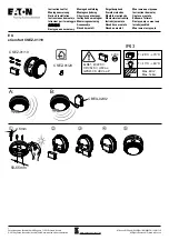
Figure 1: Candela switch
1. Candela
switch
2. Indicator
GE
Security
Genesis Ceiling Horn-Strobe
Installation Sheet