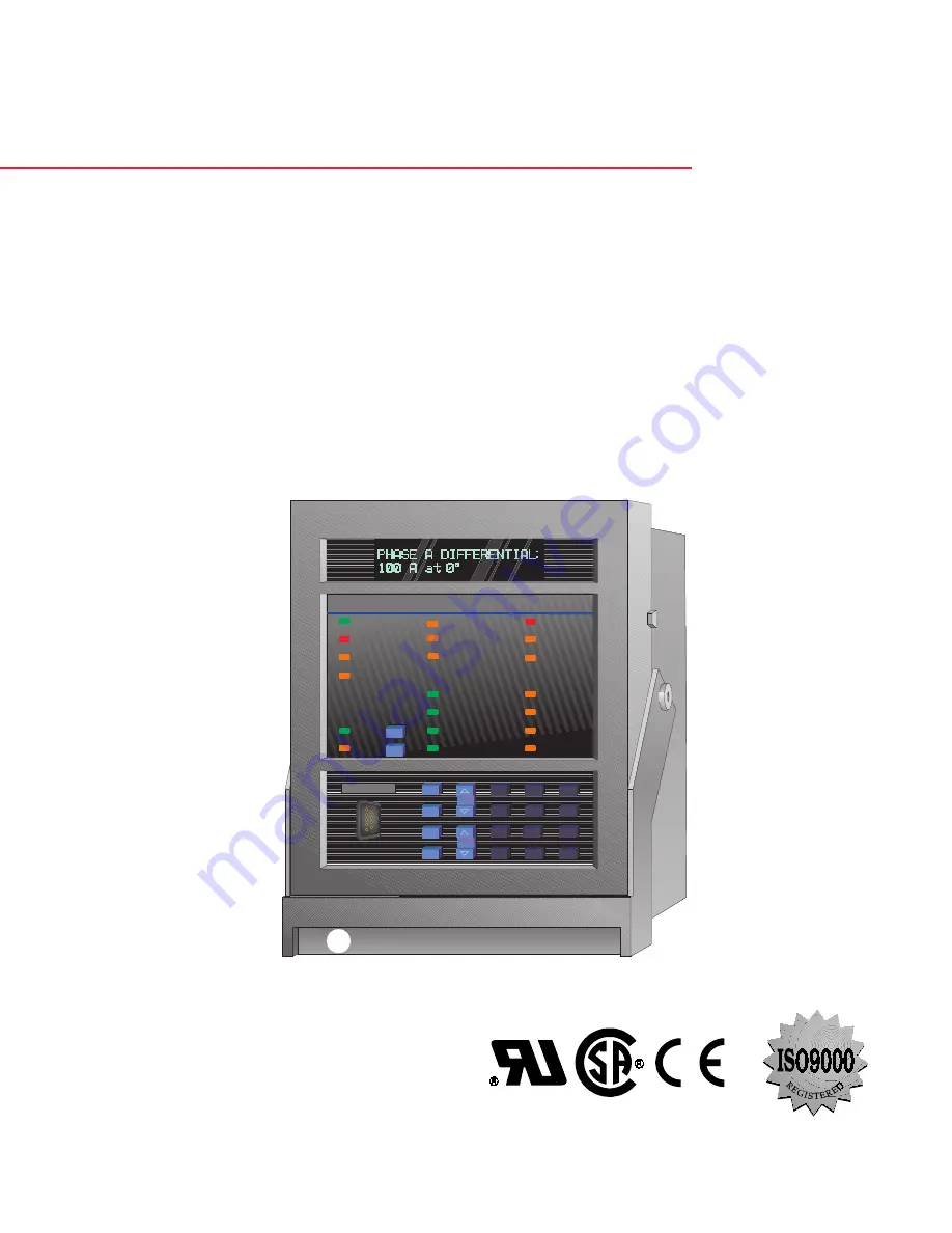
background image

745

TRANSFORMER MANAGEMENT RELAY™

INSTRUCTION MANUAL

Firmware Revision: 250.000

Manual P/N: 1601-0070-B2 (GEK-106292)

Copyright © 2001 GE Power Management

GE Power Management

215 Anderson Avenue, Markham, Ontario

Canada L6E 1B3

Tel: (905) 294-6222   Fax: (905) 294-8512

Internet: http://www.GEindustrial.com/pm

Manufactured under an

ISO9001 Registered system.

g

GE Power Management

745

Transformer Management Relay

814768AF.CDR

IN SERVICE

LOCAL

SETPOINT GROUP 2

LOAD-LIMIT

REDUCED

TRIP

SELF-TEST

ERROR

SETPOINT GROUP 3

TRANSFORMER

DE-ENERGIZED

ALARM

PICKUP

TEST MODE

TRANSFORMER

OVERLOAD

SETPOINT GROUP 1

PHASE A

PHASE B

PHASE C

GROUND

MESSAGE

PROGRAM PORT

SETPOINT

7

8

9

4

5

6

1

2

3

.

0

HELP

MESSAGE

VALUE

ACTUAL

ESCAPE

ENTER

RESET

NEXT

DIFFERENTIAL

BLOCKED

745 STATUS

SYSTEM STATUS

CONDITIONS

SETPOINT GROUP 4

g

Summary of Contents for 745 TRANSFORMER MANAGEMENT RELAY

Page 1: ...ufactured under an ISO9001 Registered system g GE Power Management 745 Transformer Management Relay 814768AF CDR IN SERVICE LOCAL SETPOINT GROUP 2 LOAD LIMIT REDUCED TRIP SELF TEST ERROR SETPOINT GROUP 3 TRANSFORMER DE ENERGIZED ALARM PICKUP TEST MODE TRANSFORMER OVERLOAD SETPOINT GROUP 1 PHASE A PHASE B PHASE C GROUND MESSAGE PROGRAM PORT SETPOINT 7 8 9 4 5 6 1 2 3 0 HELP MESSAGE VALUE ACTUAL ESC...

Page 2: ...hould further information be desired or should particular problems arise which are not covered sufficiently for the purchaser s purpose the matter should be referred to the General Electric Company To the extent required the products described herein meet applicable ANSI IEEE and NEMA standards but no such assurance is given with respect to local codes and ordi nances because they vary greatly ...

Page 3: ...PASSCODE 2 6 b DISABLING ENABLING PASSCODE SECURITY 2 7 3 INSTALLATION 3 1 DRAWOUT CASE 3 1 1 CASE DESCRIPTION 3 1 3 1 2 PANEL CUTOUT 3 1 3 1 3 CASE MOUNTING 3 2 3 1 4 UNIT WITHDRAWAL AND INSERTION 3 2 a RELAY WITHDRAWAL 3 2 b RELAY INSERTION 3 3 c DRAWOUT SEAL 3 3 3 2 TYPICAL WIRING 3 2 1 DESCRIPTION 3 4 3 2 2 REAR TERMINAL LAYOUT 3 4 3 2 3 REAR TERMINAL ASSIGNMENTS 3 5 3 2 4 TYPICAL WIRING DIAGR...

Page 4: ... 2 5 CONDITION INDICATORS 4 4 a TRIP 4 4 b ALARM 4 4 c PICKUP 4 4 d PHASE A B C 4 4 e GROUND 4 4 4 2 6 PROGRAM PORT 4 4 4 3 KEYPAD 4 3 1 SETPOINT KEY 4 5 4 3 2 ACTUAL KEY 4 5 4 3 3 ESCAPE KEY 4 5 4 3 4 ENTER KEY 4 5 4 3 5 MESSAGE UP DOWN KEY 4 5 4 3 6 VALUE UP DOWN KEY 4 5 4 3 7 NUMBER KEYS 4 6 4 3 8 HELP KEY 4 6 4 3 9 RESET KEY 4 6 4 3 10 NEXT KEY 4 6 5 SETPOINTS 5 1 OVERVIEW 5 1 1 SETPOINT GROUP...

Page 5: ... INPUTS 5 5 1 DESCRIPTION 5 43 5 5 2 LOGIC INPUTS 5 43 5 5 3 VIRTUAL INPUTS 5 44 5 6 S4 ELEMENTS 5 6 1 DESCRIPTION 5 45 5 6 2 INTRODUCTION TO ELEMENTS 5 45 5 6 3 SETPOINT GROUP 5 46 5 6 4 DIFFERENTIAL 5 46 a PERCENT DIFFERENTIAL 5 46 b HARMONIC INHIBIT 5 49 c ENERGIZATION INHIBIT 5 49 d ENERGIZATION SENSING 5 50 e 5TH HARMONIC INHIBIT 5 51 5 6 5 INSTANTANEOUS DIFFERENTIAL 5 52 5 6 6 PHASE OVERCURR...

Page 6: ...AGING FACTOR LIMIT 5 74 5 6 16 LOSS OF LIFE LIMIT 5 75 5 6 17 ANALOG INPUT 5 76 a ANALOG LEVEL 1 2 5 76 5 6 18 CURRENT DEMAND 5 77 5 6 19 TRANSFORMER OVERLOAD 5 78 5 6 20 TAP CHANGER FAILURE 5 79 5 7 S5 OUTPUTS 5 7 1 DESCRIPTION 5 80 5 7 2 INTRODUCTION TO FLEXLOGIC 5 80 5 7 3 FLEXLOGIC RULES 5 82 5 7 4 OUTPUT RELAYS 5 84 5 7 5 TRACE MEMORY 5 85 5 7 6 VIRTUAL OUTPUTS 5 85 5 7 7 TIMERS 5 86 5 8 S6 T...

Page 7: ...ONIC SUB COMPONENTS 6 7 b TOTAL HARMONIC DISTORTION THD 6 7 c HARMONIC DERATING FACTOR 6 8 6 3 4 FREQUENCY 6 8 6 3 5 TAP CHANGER 6 8 6 3 6 VOLTAGE 6 9 6 3 7 DEMAND 6 9 a DEMAND DATA CLEAR 6 9 b CURRENT DEMAND 6 10 6 3 8 AMBIENT TEMPERATURE 6 10 6 3 9 LOSS OF LIFE 6 10 6 3 10 ANALOG INPUT 6 11 6 3 11 POWER 6 11 6 3 12 ENERGY 6 12 a ENERGY DATA CLEAR 6 12 b W1 W2 W3 ENERGY 6 12 6 4 A3 EVENT RECORDER...

Page 8: ...S 8 5 8 2 9 FUNCTION CODE 03H 04H READ ACTUAL VALUES SETPOINTS 8 6 8 2 10 FUNCTION CODE 05H EXECUTE OPERATION 8 7 8 2 11 FUNCTION CODE 06H STORE SINGLE SETPOINT 8 8 8 2 12 FUNCTION CODE 10H STORE MULTIPLE SETPOINTS 8 9 8 2 13 EXCEPTION RESPONSES 8 10 8 2 14 READING THE EVENT RECORDER 8 11 8 2 15 READING TRACE MEMORY 8 11 8 2 16 ACCESSING DATA VIA THE USER MAP 8 12 8 2 17 FUNCTION CODE SUBSTITUTION...

Page 9: ...10 6 10 4 2 OUTPUT RELAYS 10 7 a PROCUDURE 10 7 10 5 DISPLAY METERING COMMUNICATIONS ANALOG OUTPUTS 10 5 1 DESCRIPTION 10 8 10 5 2 CURRENT INPUTS 10 8 10 5 3 VOLTAGE INPUT 10 9 10 5 4 TRANSFORMER TYPE SELECTION 10 9 a AUTOMATIC TRANSFORMATION PERFORMED IN THE 745 10 9 b EFFECTS OF ZERO SEQUENCE COMPONENT REMOVAL 10 10 10 5 5 AMBIENT TEMPERATURE INPUT 10 11 a BASIC CALIBRATION OF RTD INPUT 10 11 b ...

Page 10: ...WINDING 3 ELEMENTS 10 25 10 6 8 NEUTRAL INSTANTANEOUS OVERCURRENT 1 10 26 a WINDING 1 ELEMENT 10 26 b PICKUP LEVEL 10 26 c OPERATING TIME 10 26 d WINDING 2 AND 3 ELEMENTS 10 26 10 6 9 NEUTRAL INSTANTANEOUS OVERCURRENT 2 10 27 10 6 10 GROUND TIME OVERCURRENT 10 27 a WINDING 1 ELEMENT 10 27 b PICKUP LEVEL 10 27 c OPERATING TIME 10 28 d RESET TIME 10 28 e WINDING 2 OR 3 ELEMENTS 10 28 10 6 11 GROUND ...

Page 11: ...NG 10 42 a PRELIMINARIES 10 42 b HOTTEST SPOT LIMIT 10 42 c AGING FACTOR LIMIT 10 42 d LOSS OF LIFE LIMIT 10 42 10 6 24 TAP MONITOR FAILURE 10 42 10 7 AUXILIARY PROTECTION MONITORING FUNCTIONS 10 7 1 THD LEVEL SCHEME 10 43 a MINIMUM PICKUP 10 43 b OPERATING TIME 10 43 c MINIMUM OPERATING CURRENT 10 43 d OTHER THD ELEMENTS 10 43 10 7 2 HARMONIC DERATING FUNCTION 10 44 a OPERATING LEVEL 10 44 b OPER...

Page 12: ...x 745 Transformer Management Relay GE Power Management TABLE OF CONTENTS C WARRANTY C 1 WARRANTY INFORMATION C 1 1 WARRANTY C 1 ...

Page 13: ...nts with high harmonic content Multiple Setpoint Groups which allow the user to enter and dynamically select from up to four groups of relay settings to address the protection requirements of different power system configurations Dynamic CT Ratio Mismatch Correction which monitors the on load tap position and automatically corrects for CT ratio mismatch FlexLogic which allows PLC style equations b...

Page 14: ...t AN 1 Analog Input Level 1 2THD Total Harmonic Distortion Level AN 2 Analog Input Level 2 2AD Current Demand Insulation Aging Aging Factor Hottest Spot Limit Total Accumulated Life Tap Changer Monitor SYMBOL WINDING 1 PROTECTION ELEMENT SYMBOL WINDING 3 PROTECTION ELEMENT 150 46 Negative Sequence Instantaneous O C 350 46 Negative Sequence Instantaneous O C 151 46 Negative Sequence Time O c 351 46...

Page 15: ...GE Power Management 745 Transformer Management Relay 1 3 1 PRODUCT OVERVIEW 1 1 INTRODUCTION 1 Figure 1 1 SINGLE LINE DIAGRAM 745 ...

Page 16: ...GS W2 2 WINDING W3 3 WINDING WINDING WINDING 1 1 2 2 2 3 3 P1 P5 P15 P51 P115 P151 P155 P511 P515 P551 G1 G5 G15 G51 1 A 5 A 1 A 5 A 1 A 1 A 1 A 5 A 5 A 5 A 1 A 5 A 1 A 5 A 1 A 5 A 5 A 1 A 1 A 5 A 5 A 1 A 1 A 5 A 1 A 5 A 5 A 1 A 1 A 5 A 5 A 1 A 5 A 1 A 5 A 1 A OPTIONS A ANALOG INPUT OUTPUTS L LOSS OF LIFE R RESTRICTED GROUND FAULT CONTROL POWER LO 24 60 Vdc 20 48 Vac 48 62 Hz HI 90 300 Vdc 70 265 ...

Page 17: ...rdering Burden Less than 0 2 VA at rated load per phase Conversion Range 0 02 to 46 CT Accuracy at 4 x CT 0 25 of 4 CT 0 01 CT at 4 x CT 0 5 of 46 CT 0 2 CT Overload Withstand 1 second at 80 times rated current 2 seconds at 40 times rated current continuous at 3 times rated current GROUND CURRENT INPUT Source CT 1 to 50000 A primary 1 or 5 A secondary Relay Input 1 A or 5 A specified when ordering...

Page 18: ...ating Current Pickup 0 05 to 1 00 in steps of 0 01 x CT Dropout Level 97 to 98 of Pickup SLOPE 1 Range 15 to 100 in steps of 1 SLOPE 2 Range 50 to 200 in steps of 1 KP SLOPE 1 Kneepoint 1 0 to 20 0 in steps of 0 1 x CT Harmonic Restraint 0 1 to 65 0 in steps of 0 1 Operate Time Solid State Output Pickup 1 x CT 42 to 52 ms 1 x CT Pickup 1 1 kneepoint 34 to 44 ms Pickup 1 1 kneepoint 26 to 36 ms Rel...

Page 19: ... to 30 ms at 2 0 pickup 18 to 26 ms at 4 0 pickup 11 to 19 ms Relay Outputs 2 5 at 1 2 pickup 28 to 36 ms at 2 0 pickup 24 to 32 ms at 4 0 pickup 17 to 25 ms UNDERFREQUENCY 2 ELEMENTS Operating Current Pickup 0 05 to 1 00 in steps of 0 01 CT Operating Voltage Pickup 0 10 to 0 99 in steps of 0 01 VT Pickup Level 45 00 to 59 99 in steps of 0 01 Hz Dropout Level Pickup 0 03 Hz Time Delay 0 00 to 600 ...

Page 20: ...curve IEC Curve A B C Time Delay 0 00 to 600 00 s in steps of 0 01 s Reset Delay 0 0 to 6000 0 s in steps of 0 1 s Signal Source Voltage Range 10 to 65 Hz Level Accuracy 0 02 V Hz Operate Time Solid State Output at 1 10 pickup 165 to 195 ms Relay Outputs 2 5 at 1 10 pickup 170 to 200 ms delay set to 0 0 s OVEREXCITATION ON 5TH HARMONIC LEVEL Operating Current Pickup 0 03 to 1 00 in steps of 0 01 C...

Page 21: ...VIRONMENT Operating Temperature Range 40 C to 60 C Ambient Storage Temperature 40 C to 80 C Humidity up to 90 non condensing Altitude 2000 m Pollution degree II RELAYS 2 5 TRIP RELAYS 6 8 AUXILIARY 9 SELF TEST VOLTAGE MAKE CARRY CONTINUOUS MAKE CARRY 0 2s BREAK MAX LOAD VOLTAGE MAKE CARRY CONTINUOUS MAKE CARRY 0 2s BREAK MAX LOAD DC Resistive 30 V DC 20 A 40 A 10 A 300 W DC Resistive 30 V DC 10 A ...

Page 22: ...ntial modes 2 kV per ANSI IEEE C37 90 1 IEC 255 22 1 and Ontario Hydro A 28M 82 Voltage Dips per IEC 1000 4 1 0 40 Electrostatic Discharge per IEC 255 22 2 8 15 kV Power Frequency Magnetic Field Immunity per EN 61000 4 8 Damp Heat Cyclic Humidity per IEC 68 2 30 6 days Temperature Cycle 40 C 60 C Mechanical Stress 2 g Make and Carry Rating 30 A Current Withstand per ANSI IEEE C37 90 40 rated A for...

Page 23: ...setpoints for entering the characteristics of the power transformer being protected Repeatedly press the key to display the 3rd 4th 5th and 6th page headers and then back to the first setpoints page header As you have discovered there are 6 setpoint pages in all numbered from S1 the S prefix indicating that it is a setpoint page to S6 y PASSCODE y ENTER for more From the page one header of setpoin...

Page 24: ...re a message is located in the 745 relay For this last mes sage the path would be S1 745 SETUP PREFERENCES DEFAULT MESSAGE INTENSITY For the purposes of this manual we will refer to messages in this manner Press the key to return to the preferences sub header message Pressing the key from any of the messages under a sub header will return the display to that sub header message From a sub header me...

Page 25: ...ng a numerical setpoint value are available 1 0 to 9 and the decimal key The relay numeric keypad works the same as that of any electronic calculator A number is entered one digit at a time The leftmost digit is entered first and the rightmost digit is entered last Pressing the key before the key returns the original value to the display 2 and The key increments the displayed value by the step val...

Page 26: ...sh message momentarily appears to confirmation the storing process If 69 28 were entered the value is automatically rounded to 69 3 since the step value for this setpoint is 0 1 PHASE SEQUENCE ABC Move to message S2 SYSTEM SETUP TRANSFORMER PHASE SEQUENCE yy PRESS VALUEÚ Ú TO yy MAKE SELECTION Press the key and the following context sensitive flash messages will sequentially appear for several sec...

Page 27: ...TO yy STORE CHARACTER yy AND ADVANCE TO yy NEXT POSITION yy FOR FURTHER HELP yy REFER TO MANUAL OUTPUT 2 NAME Trip 2 The text entered here should be more descriptive to this output relay For this example let us rename output relay as INST DIFF TRIP Press the key and a solid cursor z will appear in the first character position OUTPUT 3 NAME INST DIFF TRIP Press or key until the character I is displ...

Page 28: ...ed The passcode is also defaulted to 0 which disables the passcode security feature entirely CHANGE PASSCODE No Press the key once CHANGE PASSCODE Yes Press the or key once PLEASE ENTER CURRENT PASSCODE Press the key to begin the procedure of changing the passcode The displayed message will change as shown The current passcode is 0 so press the 0 numeric key The relay will acknowledge the key pres...

Page 29: ... key This flash message indicates that the keyed in value was accepted and that passcode security is now disabled RESTRICT ACCESS TO SETPOINTS No This message will appear after a few seconds Now that setpoint access is enabled the ALLOW ACCESS TO SETPOINTS message has been replaced by the RESTRICT ACCESS TO SETPOINTS message The relay s setpoints can now be altered and stored If no front panel key...

Page 30: ...2 8 745 Transformer Management Relay GE Power Management 2 3 SECURITY 2 GETTING STARTED 2 ...

Page 31: ... case connectors are fitted with mechanisms such as automatic CT shorting to allow the safe removal of the relay from an energized panel There are no electronic components in the case Figure 3 1 CASE DIMENSIONS 3 1 2 PANEL CUTOUT A 745 can be mounted alone or adjacent to another SR series unit on a standard 19 rack panel Panel cutout dimensions for both conditions are as shown When planning the lo...

Page 32: ...case will be securely mounted so that its relay can be inserted The SR unit is now ready for panel wiring Figure 3 3 CASE MOUNTING 3 1 4 UNIT WITHDRAWAL AND INSERTION TURN OFF CONTROL POWER BEFORE DRAWING OUT OR RE INSERTING THE RELAY TO PREVENT MALOPERATION a RELAY WITHDRAWAL 1 Open the door by pulling from the center of its right side It will rotate to the left about its hinges 2 Press upward on...

Page 33: ...ndle raised align and slide both rolling guide pins into the case guide slots Each rolling guide pin is found near the hinges of the relay s handle 2 Once fully inserted grasp the handle from its center and rotate it down from the raised position towards the bottom of the relay 3 As the handle is fully inserted the latch will be heard to click locking the handle in the final position The unit is m...

Page 34: ...y a broad range of applications are available to the user As such it is not possible to present connections for all possible schemes The information in this section will cover the important aspects of interconnections in the general areas of instrument transformer inputs other inputs outputs communications and grounding 3 2 2 REAR TERMINAL LAYOUT Figure 3 6 REAR TERMINAL LAYOUT ...

Page 35: ...5 F7 OUTPUT 7 AUXILIARY RELAY N O B8 IRIG B F8 OUTPUT 7 AUXILIARY RELAY N C B9 IRIG B F9 OUTPUT 8 AUXILIARY RELAY Common B10 RTD 1 HOT F10 OUTPUT 9 SERVICE RELAY N O B11 RTD 1 COMPENSATION F11 OUTPUT 9 SERVICE RELAY N C B12 RTD 1 RETURN F12 GROUND WINDING 2 3 CT n LOGIC INPUTS 9 16 VT INPUT CT INPUTS 745 GROUNDING C1 LOGIC INPUT 9 G1 PHASE A WINDING 1 CT C2 LOGIC INPUT 10 G2 PHASE B WINDING 1 CT C...

Page 36: ...3 6 745 Transformer Management Relay GE Power Management 3 2 TYPICAL WIRING 3 INSTALLATION 3 3 2 4 TYPICAL WIRING DIAGRAMS Figure 3 7 TYPICAL WIRING DIAGRAM g ...

Page 37: ...GE Power Management 745 Transformer Management Relay 3 7 3 INSTALLATION 3 2 TYPICAL WIRING 3 Figure 3 8 TYPICAL WIRING DIAGRAM FOR GENERATOR STEP UP g ...

Page 38: ...urrent inputs Current transformers with 1 to 50 000 A primaries may be used Verify that the relay s nominal current of 1 A or 5 A matches the secondary rating of the con nected CTs Unmatched CTs may result in equipment damage or inadequate protection The exact placement of a zero sequence CT so that ground fault current will be detected is shown below Twisted pair cabling on the zero sequence CT i...

Page 39: ...is range Figure 3 10 CONTROL POWER CONNECTION 3 2 9 LOGIC INPUTS Correct polarity must be observed for all logic input connections or equipment damage may result External contacts can be connected to the 16 logic inputs As shown these contacts can be either dry or wet It is also possible to use a combination of both contact types A dry contact has one side connected to terminal D11 This is the 32 ...

Page 40: ...internally to a 4 3 mA current source This cur rent is used to measure the value of the external resistance The 745 uses the measured resistance value to calculate the Tap Position 3 2 12 RTD DRIVER SENSOR Terminals B10 RTD HOT B11 RTD COMP and B12 RTD RET provide for the connection of various types of RTD devices This connection may be made using two or three wires to the RTD Terminal B10 is conn...

Page 41: ... 0 to 5 mA 0 to 10 mA 0 to 20 mA 4 to 20 mA Each analog output channel can be programmed to represent one of the parameters measured by the relay For details see the setpoints chapter As shown in the typical wiring diagram the analog output signals originate from terminals A6 to A12 and share A5 as a common return Output signals are internally isolated and allow connection to devices which sit at ...

Page 42: ...use of shielded twisted pair wire is recommended Correct polarity should also be observed For instance the relays must be connected with all B1 terminals labeled COM1 RS485 connected together and all B2 terminals labeled COM1 RS485 connected together Terminal B3 labeled COM1 RS485 COM should be connected to the common wire inside the shield To avoid loop currents the shield should be grounded at o...

Page 43: ...L PROGRAM PORT A 9 pin RS232C serial port is located on the front panel for programming through a PC This port uses the same Modbus protocol as the two rear ports The 745PC software required to use this interface is included with the relay Cabling for the RS232 port is shown below for both 9 pin and 25 pin connectors Figure 3 15 RS232 CONNECTION ...

Page 44: ...nchronized Figure 3 16 IRIG B FUNCTION 3 2 19 DIELECTRIC STRENGTH TESTING Dielectric strength test was performed on the 745 relay at the manufacturer It is not necessary to perform this test again at the customer site However if you wish to perform this test follow instructions outlined in Section 10 3 2 DIELECTRIC STRENGTH TESTING on page 10 5 No special ventilation requirements need to be observ...

Page 45: ...RS232 program port is also provided for connection with a computer running the 745PC software Figure 4 1 745 FRONT PANEL 745 Transformer Management Relay FrontPanel CDR IN SERVICE LOCAL SETPOINT GROUP 2 LOAD LIMIT REDUCED TRIP SELF TEST ERROR SETPOINT GROUP 3 TRANSFORMER DE ENERGIZED ALARM PICKUP TEST MODE TRANSFORMER OVERLOAD SETPOINT GROUP 1 PHASE A PHASE B PHASE C GROUND MESSAGE PROGRAM PORT SE...

Page 46: ...have been detected The color of each indicator conveys information about its importance GREEN G indicates a general condition AMBER A indicates an alert condition RED R indicates a serious alarm or warning All indicators can be tested by pressing while no conditions are active 4 2 3 STATUS INDICATORS a IN SERVICE The IN SERVICE indicator is on when relay protection is operational The indicator is ...

Page 47: ...er is de energized The indicator is on if the S4 ELEMENTS DIFFERENTIAL ENERGIZATN INHIBIT feature is detecting the transformer as de energized b TRANSFORMER OVERLOAD The TRANSFORMER OVERLOAD indicator is on when S4 ELEMENTS XFORMER OVERLOAD has operated c LOAD LIMIT REDUCED The LOAD LIMIT REDUCED indicator is on when the adaptive harmonic factor cor rection feature is detecting enough harmonic con...

Page 48: ...he PHASE A B C indicator is on when phase A B C is involved in the condition detected by any element that has picked up operated or is now in a latched state waiting to be reset e GROUND The GROUND indicator is on when ground is involved in the condition detected by any element that has picked up operated or is now in a latched state waiting to be reset 4 2 6 PROGRAM PORT Use the front panel progr...

Page 49: ...her situations moves the display to the next higher header message This continues until the current sub header is reached 4 3 4 ENTER KEY The context sensitive key response depends on the displayed message and the relay status While dis playing a sub header whose lower line reads ENTER for more press to enter the group of messages associated with the upper line After editing setpoints numerically ...

Page 50: ...l mode puts all latched relays to the non operated state and clears latched targets if initiating conditions are no longer present 4 3 10 NEXT KEY If a target becomes active a diagnostic message overrides the displayed message and the MESSAGE indica tor flashes If there is more than one target active scrolls through the messages Pressing any other key returns to the normally displayed messages Whi...

Page 51: ...Analog Input Demand Metering Analog Outputs yy SETPOINTS yy S3 LOGIC INPUTS Logic Inputs 1 to 16 Virtual Inputs 1 to 16 yy SETPOINTS yy S4 ELEMENTS Setpoint Group active group and edit group Differential percent differential harmonic energization 5th harmonic inhibits Instantaneous Differential Phase Overcurrent time and instantaneous for all windings Neutral Overcurrent time and instantaneous for...

Page 52: ...the relay leaves the factory The following diagnostic message appears until the 745 is put in the pro grammed state Messages may vary somewhat from those illustrated because of installed options Also some messages asso ciated with disabled features or optional features which have not been ordered are hidden These messages are shown with a shaded message box KEYPAD ENTRY See Section 2 1 USING THE F...

Page 53: ...s to obtain extremely accurate differential currents 5 2 2 A TYPICAL POWER TRANSFORMER Consider a WYE DELTA power transformer with the following data Connection Y d30 i e DELTA winding phases lag corresponding WYE winding phases by 30 Winding 1 100 133 166 MVA 220 kV nominal 500 1 CT ratio Winding 2 100 133 166 MVA 69 kV nominal 1500 1 CT ratio onload tap changer 61 to 77 kV in 0 5 kV steps 33 tap...

Page 54: ...fectly matched Winding 2 CT ratio based on the tap changer position is calculated as follows where n current tap changer position V2 min Winding 2 minimum voltage at n 1 V2 tap Winding 2 voltage increment per tap Thus with the tap changer at position 33 the Winding 2 CT ratio must be 1428 6 1 to be perfectly matched In this case the mismatch factor is 1428 6 1500 0 952 745 Solution The 745 allows ...

Page 55: ...he indication circuit as illustrated below Figure 5 1 TAP POSITION INPUT The zero position terminal and the wiper terminal of the tap position circuit are connected to the positive and negative 745 tap position terminals Polarity is not consequential The following setpoints configure the 745 to determine tap position Under S2 SYSTEM SETUP ONLOAD TAP CHANGER WINDING WITH TAP CHANGER Winding 2 NUMBE...

Page 56: ...is standard the arbitrary labeling of the windings is shown as I II and III This stan dard specifically states that the phase relationships are established for a condition where a source phase sequence of I II III is connected to transformer windings labeled I II and III respectively The source phase sequence must be stated when describing the winding phase relationships since these rela tionships...

Page 57: ...he delta winding have not changed The transformer nameplate phase relationship information is only correct for a stated phase sequence It may be suggested that for the ACB sequence the phase relationship can be returned to that shown on the transformer nameplate by connecting source phases A B and C to transformer terminals A C and B respec tively This will restore the nameplate phase shifts but w...

Page 58: ...Delta arrangement This compensates for the phase angle lag introduced in the Delta side Winding 2 The 745 performs this phase angle correction internally based on the following setpoint Under S2 SYSTEM SETUP TRANSFORMER set The 745 supports over 100 two and three winding transformer types Table 5 1 TRANSFORMER TYPES on page 5 10 provides the following information about each transformer type TRANSF...

Page 59: ...s having an in zone grounding bank on the Delta side and the Wye connected CTs on the same side Traditionally this problem is solved by inserting a zero sequence current trap in the CT circuitry The 745 automatically removes zero sequence current from all Delta winding currents when calculating differential current Where there is no source of zero sequence current e g Delta windings not having a g...

Page 60: ...80 lag 2 WYE gnd 2 3 180 lag 0 Y d30 1 WYE gnd 1 2 30 lag 2 DELTA 30 lag 0 Y d150 1 WYE gnd 1 2 150 lag 2 DELTA 150 lag 0 Y d210 1 WYE gnd 1 2 210 lag 2 DELTA 210 lag 0 Y d330 1 WYE gnd 1 2 330 lag 2 DELTA 330 lag 0 D d0 1 DELTA 0 2 DELTA 0 0 D d60 1 DELTA 60 lag 2 DELTA 60 lag 0 D d120 1 DELTA 120 lag 2 DELTA 120 lag 0 D d180 1 DELTA 180 lag 2 DELTA 180 lag 0 D d240 1 DELTA 240 lag 2 DELTA 240 la...

Page 61: ...WYE gnd 1 2 210 lag 2 ZIG ZAG gnd 2 3 210 lag 0 Table 5 1 TRANSFORMER TYPES Sheet 3 of 26 TRANSFORMER TYPE WDG CONNECTION VOLTAGE PHASORS PHASE SHIFT Y z330 1 WYE gnd 1 2 330 lag 2 ZIG ZAG gnd 2 3 330 lag 0 D z0 1 DELTA 0 2 ZIG ZAG gnd 1 2 0 lag 0 D z60 1 DELTA 60 lag 2 ZIG ZAG gnd 1 2 60 lag 0 D z120 1 DELTA 120 lag 2 ZIG ZAG gnd 1 2 120 lag 0 D z180 1 DELTA 180 lag 2 ZIG ZAG gnd 1 2 180 lag 0 D ...

Page 62: ... 3 0 210 lag 3 DELTA 210 lag 0 Table 5 1 TRANSFORMER TYPES Sheet 5 of 26 TRANSFORMER TYPE WDG CONNECTION VOLTAGE PHASORS PHASE SHIFT Y y0 d330 1 WYE gnd 1 2 330 lag 2 WYE gnd 2 3 0 330 lag 3 DELTA 330 lag 0 Y y180 d30 1 WYE gnd 1 2 30 lag 2 WYE gnd 2 3 180 lag 210 lag 3 DELTA 30 lag 0 Y y180 d150 1 WYE gnd 1 2 150 lag 2 WYE gnd 2 3 180 lag 330 lag 3 DELTA 150 lag 0 Y y180 d210 1 WYE gnd 1 2 210 la...

Page 63: ...gnd 1 2 30 lag 2 DELTA 30 lag 0 3 DELTA 30 lag 0 Table 5 1 TRANSFORMER TYPES Sheet 7 of 26 TRANSFORMER TYPE WDG CONNECTION VOLTAGE PHASORS PHASE SHIFT Y d30 d150 1 WYE gnd 1 2 30 lag 2 DELTA 30 lag 0 3 DELTA 150 lag 240 lag Y d30 d210 1 WYE gnd 1 2 30 lag 2 DELTA 30 lag 0 3 DELTA 210 lag 180 lag Y d30 d330 1 WYE gnd 1 2 30 lag 2 DELTA 30 lag 0 3 DELTA 330 lag 60 lag Y d150 y0 1 WYE gnd 1 2 150 lag...

Page 64: ...ag 2 DELTA 150 lag 0 3 DELTA 210 lag 300 lag Table 5 1 TRANSFORMER TYPES Sheet 9 of 26 TRANSFORMER TYPE WDG CONNECTION VOLTAGE PHASORS PHASE SHIFT Y d150 d330 1 WYE gnd 1 2 150 lag 2 DELTA 150 lag 0 3 DELTA 330 lag 180 lag Y d210 y0 1 WYE gnd 1 2 210 lag 2 DELTA 210 lag 0 3 WYE gnd 2 3 0 210 lag Y d210 y180 1 WYE gnd 1 2 210 lag 2 DELTA 210 lag 0 3 WYE gnd 2 3 180 lag 30 lag Y d210 d30 1 WYE gnd 1...

Page 65: ...ELTA 330 lag 0 3 WYE gnd 2 3 0 330 lag Table 5 1 TRANSFORMER TYPES Sheet 11 of 26 TRANSFORMER TYPE WDG CONNECTION VOLTAGE PHASORS PHASE SHIFT Y d330 y180 1 WYE gnd 1 2 330 lag 2 DELTA 330 lag 0 3 WYE gnd 2 3 180 lag 150 lag Y d330 d30 1 WYE gnd 1 2 330 lag 2 DELTA 330 lag 0 3 DELTA 30 lag 300 lag Y d330 d150 1 WYE gnd 1 2 330 lag 2 DELTA 330 lag 0 3 DELTA 150 lag 180 lag Y d330 d210 1 WYE gnd 1 2 ...

Page 66: ...ag 2 DELTA 0 120 lag 3 DELTA 120 lag 0 Table 5 1 TRANSFORMER TYPES Sheet 13 of 26 TRANSFORMER TYPE WDG CONNECTION VOLTAGE PHASORS PHASE SHIFT D d0 d180 1 DELTA 180 lag 2 DELTA 0 180 lag 3 DELTA 180 lag 0 D d0 d240 1 DELTA 240 lag 2 DELTA 0 240 lag 3 DELTA 240 lag 0 D d0 d300 1 DELTA 300 lag 2 DELTA 0 300 lag 3 DELTA 300 lag 0 D d0 y30 1 DELTA 0 2 DELTA 0 0 3 WYE gnd 2 3 30 lag 330 lag Table 5 1 TR...

Page 67: ...Table 5 1 TRANSFORMER TYPES Sheet 15 of 26 TRANSFORMER TYPE WDG CONNECTION VOLTAGE PHASORS PHASE SHIFT D d60 d60 1 DELTA 60 lag 2 DELTA 60 lag 0 3 DELTA 60 lag 0 D d60 d240 1 DELTA 240 lag 2 DELTA 60 lag 180 lag 3 DELTA 240 lag 0 D d60 y30 1 DELTA 0 2 DELTA 60 lag 300 lag 3 WYE gnd 2 3 30 lag 330 lag D d60 y210 1 DELTA 0 2 DELTA 60 lag 300 lag 3 WYE gnd 2 3 210 lag 150 lag D d120 d0 1 DELTA 120 la...

Page 68: ...30 lag 30 lag D d180 d0 1 DELTA 180 lag 2 DELTA 180 lag 0 3 DELTA 0 180 lag Table 5 1 TRANSFORMER TYPES Sheet 17 of 26 TRANSFORMER TYPE WDG CONNECTION VOLTAGE PHASORS PHASE SHIFT D d180 d120 1 DELTA 120 lag 2 DELTA 180 lag 300 lag 3 DELTA 120 lag 0 D d180 d180 1 DELTA 0 2 DELTA 180 lag 180 lag 3 DELTA 180 lag 180 lag D d180 d300 1 DELTA 300 lag 2 DELTA 180 lag 120 lag 3 DELTA 300 lag 0 D d180 y150...

Page 69: ...ag 120 lag 3 WYE gnd 2 3 30 lag 330 lag Table 5 1 TRANSFORMER TYPES Sheet 19 of 26 TRANSFORMER TYPE WDG CONNECTION VOLTAGE PHASORS PHASE SHIFT D d240 y210 1 DELTA 0 2 DELTA 240 lag 120 lag 3 WYE gnd 2 3 210 lag 150 lag D d300 d0 1 DELTA 300 lag 2 DELTA 300 lag 0 3 DELTA 0 300 lag D d300 d180 1 DELTA 300 lag 2 DELTA 300 lag 0 3 DELTA 180 lag 120 lag D y30 d60 1 DELTA 0 2 WYE gnd 1 2 30 lag 330 lag ...

Page 70: ... lag 210 lag 3 DELTA 120 lag 240 lag Table 5 1 TRANSFORMER TYPES Sheet 21 of 26 TRANSFORMER TYPE WDG CONNECTION VOLTAGE PHASORS PHASE SHIFT D y150 d180 1 DELTA 0 2 WYE gnd 1 2 150 lag 210 lag 3 DELTA 180 lag 180 lag D y150 d300 1 DELTA 0 2 WYE gnd 1 2 150 lag 210 lag 3 DELTA 300 lag 60 lag D y150 y150 1 DELTA 0 2 WYE gnd 1 2 150 lag 210 lag 3 WYE gnd 2 3 150 lag 210 lag D y150 y330 1 DELTA 0 2 WYE...

Page 71: ...210 lag 150 lag 3 WYE gnd 2 3 30 lag 330 lag Table 5 1 TRANSFORMER TYPES Sheet 23 of 26 TRANSFORMER TYPE WDG CONNECTION VOLTAGE PHASORS PHASE SHIFT D y210 y210 1 DELTA 0 2 WYE gnd 1 2 210 lag 150 lag 3 WYE gnd 2 3 210 lag 150 lag D y330 d0 1 DELTA 0 2 WYE gnd 1 2 330 lag 30 lag 3 DELTA 0 0 D y330 d120 1 DELTA 0 2 WYE gnd 1 2 330 lag 30 lag 3 DELTA 120 lag 240 lag D y330 d180 1 DELTA 0 2 WYE gnd 1 ...

Page 72: ... 3 150 lag 210 lag D y330 y330 1 DELTA 0 2 WYE gnd 1 2 330 lag 30 lag 3 WYE gnd 2 3 330 lag 30 lag Y z30 z30 1 WYE 30 lag 2 ZIG ZAG gnd 1 2 30 lag 0 3 ZIG ZAG gnd 2 3 30 lag 0 Table 5 1 TRANSFORMER TYPES Sheet 25 of 26 TRANSFORMER TYPE WDG CONNECTION VOLTAGE PHASORS PHASE SHIFT Y y0 y0 1 WYE 0 2 WYE gnd 1 2 0 0 3 WYE gnd 2 3 0 0 Table 5 1 TRANSFORMER TYPES Sheet 26 of 26 TRANSFORMER TYPE WDG CONNE...

Page 73: ...m with a phasor rotation of ACB interchange all B b and C c designations Table 5 2 PHASE SHIFTS PHASE SHIFT INPUT PHASORS OUTPUT PHASORS PHASOR TRANSFORMATION PHASE SHIFT INPUT PHASORS OUTPUT PHASORS PHASOR TRANSFORMATION 0 a A b B c C 180 lag a A b B c C 30 lag a A C 3 b B A 3 c C B 3 210 lag a C A 3 b A B 3 c B C 3 60 lag a C b A c B 240 lag a C b A c B 90 lag a B C 3 b C A 3 c A B 3 270 lag a C...

Page 74: ...ited directly It indicates whether passcode protection is enabled Read Only or disabled Read Write RESTRICT SETPOINT WRITE ACCESS No Range No Yes This message is only displayed when setpoint write access is allowed and the current passcode is not 0 Select Yes and follow directions to restrict write access This message is replaced by ALLOW SETPOINT WRITE ACCESS when write access is restricted ALLOW...

Page 75: ...esponse to certain key presses during setpoint programming The time these messages remain on the display overriding the normal messages can be changed to accommodate different user reading rates DEFAULT MESSAGE TIMEOUT 300 s Range 10 to 900 s in steps of 1 s After this period of time of no activity on the keys the 745 automatically begins to display the programmed set of default messages programme...

Page 76: ...tion port This setpoint cannot be changed via the communication ports All relays on the communication link and the computer connecting them must run at the same baud rate The fastest response is obtained at 19200 baud COM1 PARITY None Range None Even Odd The data frame is fixed at 1 start 8 data and 1 stop bit If required a parity bit is programmable This setpoint cannot be changed via the communi...

Page 77: ... confirmation mode desired for responses sent by the 745 When Sometimes is selected data link confirmation is only requested when the response contains more than one frame DATA LINK CONFIRM TIMOUT 1000 ms Range 1 to 65000 Steps of 1 Select a desired timeout If no confirmation response is received within this time the 745 will resend the frame if retries are still available DATA LINK CONFIRM RETRIE...

Page 78: ...ts press or press to go to the next section LOCAL RESET BLOCK Disabled Range Disabled Logic Inpt 1 2 16 Virt Inpt 1 2 16 Output Rly 1 2 8 SelfTest Rly Virt Outpt 1 2 5 The 745 is defaulted to the local mode As a result the front panel local key is normally operational Select any logic input virtual input output relay or virtual output which when asserted or operated will block local mode and hence...

Page 79: ...tual value message to be entered as a default message so that it is displayed If user text is required go into S1 745 SETUP SCRATCHPAD and edit the text for default 3 Press the decimal key followed by while the message is displayed The screen will display PRESS ENTER TO ADD AS DEFAULT Press again while this message is being displayed The message is now added to the default message list b REMOVING ...

Page 80: ...ne character at a time using Press the key to store the edit and advance to the next character position This message may then be stored as a default message y INSTALLATION y ENTER for more This message indicates the start of the INSTALLATION section To continue these setpoints press or press to go to the next section 745 SETPOINTS Not Programmed Range Not Programmed Programmed In order to safeguar...

Page 81: ...t to set the ENABLE setpoints correctly see below Any options that are currently supported by the 745 as well as any options that are to be added should have the corresponding ENABLE setpoint set to Yes All others must be set to No For example if the 745 currently supports only the Analog I O option and the Loss Of Life option is to be added then the ENABLE ANALOG I O setpoint and the ENABLE LOSS ...

Page 82: ...tate of the option ENABLE RESTRICTED GROUND FAULT No Range No Yes Select Yes if the upgrade options set supports the Restricted Ground Fault feature and select No otherwise The default value for this setpoint reflects the current state of the option ENTER PASSCODE Range 16 hexadecimal characters 0 to 9 and A to F Press to begin entering the factory supplied upgrade passcode This setpoint has a tex...

Page 83: ...n available If the VT input is not available current from phase A of Winding 1 is used FREQUENCY TRACKING Enabled Range Enabled Disabled In situations where the AC signals contain significant amount of sub harmonic components it may be necessary to disable frequency tracking PHASE SEQUENCE ABC Range ABC ACB Enter the phase sequence of the power system Systems with an ACB phase sequence require spe...

Page 84: ...IL RISE OVER AMBIENT 10ºC Range 1 to 200 steps of 1 Required for Insulation Aging calculations XFMR THRML CAPACITY 1 00 kwh ºC Range 0 00 to 200 00 steps of 0 01 Required for Insulation Aging calculations Obtain from transformer manufacturer WINDING TIME CONST 2 00 min Range 0 25 to 15 00 steps of 0 01 Required for Insulation Aging calculations SET ACCUMULATED LOSS OF LIFE 0 x 10h Range 0 to 20000...

Page 85: ... 01 Below 1 kV 0 001 to 20 000 steps of 0 001 Enter the self cooled load rating for Winding 1 2 3 of the transformer The range for this setpoint is affected by the setting made at S2 SYSTEM SETUP TRANSFORMER LOW VOLTAGE WINDING RATING WINDING 1 PHASE CT PRIMARY 500 5 A Range 1 to 50000 steps of 1 Enter the phase CT primary current rating of the current transformers connected to Winding 1 2 3 The C...

Page 86: ... Winding 3 Enter the winding with the tap changer Enter None for a transformer with no onload tap changer or to disable this feature NUMBER OF TAP POSITIONS 33 Range 2 to 50 steps of 1 Enter the number of tap changer positions MINIMUM TAP POSITION VOLTAGE 61 0 kV Range above 5 kV 0 1 to 2000 0 steps of 0 1 1 kV to 5 kV 0 01 to 200 00 steps of 0 01 below 1 kV 0 001 to 20 000 steps of 0 001 Enter th...

Page 87: ... various levels of pickup The levels are as follows 1 03 1 05 1 1 to 6 0 in steps of 0 1 and 6 5 to 20 0 in steps of 0 5 y HARMONICS y ENTER for more This message indicates the start of the HARMONICS section To continue with this setpoint press or press to go to the next section HARMONIC DERATING ESTIMATION Disabled Range Disabled Enabled Enter Enabled to enable the harmonic derating factor calcul...

Page 88: ...ENTER for more This message indicates the start of the VOLTAGE INPUT section To continue with these setpoints press or press to go to the next section VOLTAGE SENSING Disabled Range Disabled Enabled Enter Enabled when connecting a voltage transformer to this input VOLTAGE INPUT PARAMETER W1 Van Range W1 Van W1 Vbn W1 Vcn W1 Vab W1 Vbc W1 Vca W2 Van W2 Vbn W2 Vcn W2 Vab W2 Vbc W2 Vca W3 Van W3 Vbn ...

Page 89: ...52 112 10 180 168 47 280 77 233 97 30 111 67 142 06 118 38 190 172 46 291 96 243 30 40 115 54 149 79 124 82 200 175 84 303 46 252 88 50 119 39 157 74 131 45 210 179 51 315 31 262 76 60 123 24 165 90 138 25 220 183 17 327 54 272 94 70 127 07 174 25 145 20 230 186 82 340 14 283 45 80 130 89 182 84 152 37 240 190 45 353 14 294 28 90 134 70 191 64 159 70 250 194 08 366 53 305 44 100 138 50 200 64 167 ...

Page 90: ... and advance to the next character position This name will appear in the actual value message A2 METERING ANALOG INPUT ANALOG INPUT UNITS µA Range 6 alphanumeric characters Enter the units of the quantity being read by editing the text as described above The 6 characters entered will be displayed instead of Units wherever the analog input units are displayed ANALOG INPUT RANGE 0 1 mA Range 0 1 mA ...

Page 91: ...hes the time to reach 90 of a steady state value just as the response time of an analog instrument a steady state value applied for twice the response time will indicate 99 of the value BLOCK INTERVAL Select Block Interval to calculate a linear average of the current over the programmed demand TIME INTERVAL starting daily at 00 00 00 i e 12 am The 1440 minutes per day is divided into the number of...

Page 92: ...centage of the rated load for that winding W1 2 3 fA B C THD Select to monitor the total harmonic distortion in the winding 1 2 3 phase A B C current input W1 2 3 Derating Select to monitor the harmonic derating factor i e the derated transformer capability while supplying non sinusoidal load currents in winding 1 2 3 Frequency Select to monitor the system frequency Tap Position Select to monitor ...

Page 93: ... continue these setpoints press or press to go to the next section y LOGIC INPUT 1 y ENTER for more This message indicates the start of the logic input 1 2 16 setpoints To continue with these setpoints press or press to go to the next section INPUT 1 FUNCTION Disabled Range Disabled Enabled Select Enabled if this logic input is to be used Selecting Disabled will never allow this logic input to ach...

Page 94: ...is logic input to achieve the Asserted or signaling state INPUT 1 TARGET Self Reset Range None Latched Self Reset Select None to inhibit the display of the target message when the input is asserted Thus an input whose target type is None will never disable the LED self test feature because can not generate a displayable target message INPUT 1 NAME Virtual Input 1 Range 18 alphanumeric characters P...

Page 95: ...d this setpoint should be set to Disabled NAME OF ELEMENT TARGET Latched Range Self reset Latched None Target messages accessed by the key indicate which elements have picked up or operated Select Latched to keep the element target message in the queue of target messages even after the condition which caused the element to operate has been cleared until a reset command is issued Select Self reset ...

Page 96: ...tion because of unbalances between CTs during external faults These unbalances arise as a result of the following factors CT ratio mismatch not a factor since the 745 automatically corrects for this mismatch Onload tap changers which result in dynamically changing CT mismatch CT accuracy errors CT saturation y SETPOINT GROUP y ENTER for more This message indicates the start of the SETPOINT GROUP s...

Page 97: ...ifferential per phase vector sum of currents after phase ratio and zero sequence correction In the above equations the 180 phase shift due to the wiring connections is taken into account hence the sign to obtain the differential current Figure 5 7 PERCENT DIFFERENTIAL DUAL SLOPE CHARACTERISTIC Basic Operating Principle 3 winding Basic Operating Principle 2 winding Percent Diff Element CT1 CT2 CT3 ...

Page 98: ... for mismatch when operating at the limit of the transformer s onload tap changer range 2 to accommodate for CT errors PERCENT DIFFERENTIAL KNEEPOINT 2 0 x CT Range 1 0 to 20 0 steps of 0 1 Enter the kneepoint for the dual slope percent differential element This is the transition point between slopes 1 and 2 in terms of restraint current in units of relay nominal current Set the kneepoint just abo...

Page 99: ...energization current indicates energi zation 3 With b auxiliary contacts from all switching devices which can be used to energize the transformer con nected in series to a logic input and assigned to the BREAKERS ARE OPEN setpoint the contacts closed indi cates de energization any current exceeding the minimum energization current indicates energization Energization inhibit settings are put in ser...

Page 100: ...nt against HARMONIC INHIBIT LEVEL Select 2nd 5th to use the RMS sum of the 2nd and 5th harmonics HARMONIC AVERAGING Enabled Range Disabled Enabled Select Enabled to use the three phase average of the harmonic current against the harmonic inhibit setting ENERGIZATION INHIBIT LEVEL 20 0 ƒο Range 0 1 to 65 0 steps of 0 1 Enter the level of harmonic current 2nd or 2nd 5th above which the percent diffe...

Page 101: ...OLTAGE is Enabled Displayed only if S2 SYSTEM SETUP VOLTAGE INPUT VOLTAGE SENSING is Enabled BREAKERS ARE OPEN SIGNAL Disabled Range Disabled Logc Inpt 1 2 16 Select any logic input which when asserted will indicate to the 745 that the transformer is de energized The selected logic input should be connected to the auxiliary contacts of the transformer breaker or disconnect switch PARALL XFMR BRKR ...

Page 102: ...00 x CT Range 3 00 to 20 00 steps of 0 01 Enter the level of differential current in units of relay nominal current above which the instantaneous differential element will pickup and operate INST DIFFERENTIAL BLOCK Disabled Range Disabled Logc Inpt 1 2 16 Virt Inpt 1 2 16 Output Rly 1 2 8 SelfTest Rly Virt Outpt 1 2 5 y PHASE OC y ENTER for more This message indicates the start of the PHASE OVERCU...

Page 103: ...t Linear reset to coordinate with electromechanical time overcurrent relays in which the reset characteristic when the current falls below the reset threshold before tripping is proportional to ratio of energy accumulated to that required to trip Select Instantaneous reset to coordinate with relays such as most static units with instantaneous reset characteristics W1 PHASE TIME OC BLOCK Disabled R...

Page 104: ... an element whose target type is None will never disable the LED self test feature because can not generate a displayable target message W1 PHASE INST OC 1 PICKUP 10 00 x CT Range 0 05 to 20 00 steps of 0 01 Enter the level of phase current in units of relay nominal current above which the W1 2 3 phase instantaneous overcurrent 1 element will pickup and start the delay timer W1 PHASE INST OC 1 DEL...

Page 105: ...ICKUP 0 85 x CT Range 0 05 to 20 00 steps of 0 01 Enter the level of neutral current in units of relay nominal current above which the W1 2 3 neutral time overcurrent element will pickup and start timing W1 NEUTRAL TIME OC SHAPE Ext Inverse Range Ext Inverse Very Inverse Norm Inverse Mod Inverse Definite Time IEC Curve A IEC Curve B IEC Curve C IEC Short Inv IAC Ext Inv IAC Very Inv IAC Inverse IA...

Page 106: ...element whose target type is None will never disable the LED self test feature because can not generate a displayable target message W1 NEUTRAL INST OC 1 PICKUP 10 00 x CT Range 0 05 to 20 00 steps of 0 01 Enter the level of neutral current in units of relay nominal current above which the W1 2 3 neutral instantaneous overcurrent 1 element will pickup and start the delay timer W1 NEUTRAL INST OC 1...

Page 107: ...get type is None never disables the LED self test feature since it cannot generate a displayable target message W1 GROUND TIME OC PICKUP 0 85 x CT Range 0 05 to 20 00 steps of 0 01 Enter the level of ground current in units of relay nominal current above which the W1 2 3 ground time overcurrent element will pickup and start timing W1 GROUND TIME OC SHAPE Ext Inverse Range Ext Inverse Very Inverse ...

Page 108: ... element whose target type is None will never disable the LED self test feature because can not generate a displayable target message W1 GROUND INST OC 1 PICKUP 10 00 x CT Range 0 05 to 20 00 steps of 0 01 Enter the level of ground current in units of relay nominal current above which the W1 2 3 ground instantaneous overcurrent 1 element will pickup and start the delay timer W1 GROUND INST OC 1 DE...

Page 109: ...ten applied to transformers having impedance grounded wye windings It is intended to provide sensitive ground fault detection for low magnitude fault currents which would not be detected by the percent differential element Figure 5 10 RESISTANCE GROUNDED WYE WINDING y RESTRICTED GROUND y ENTER for more This message indicates the start of the RESTRICTED GROUND section To continue with these setpoin...

Page 110: ...fault point from the neutral and Figure 5 12 RGF AND PERCENT DIFFERENTIAL ZONES OF PROTECTION outlines the zones of effective protection along the winding for an impedance grounded wye Figure 5 11 FAULT CURRENTS VS FAULT POINT FROM NEUTRAL Figure 5 12 RGF AND PERCENT DIFFERENTIAL ZONES OF PROTECTION The 745 implementation of RGF Figure 5 13 RESTRICTED GROUND FAULT IMPLEMENTATION is a low impedance...

Page 111: ...er a transformer with the following specifications 10 MVA 33 kV to 11 kV 10 Impedance Delta Wye30 Rg 6 3 ohms CT Ratio 600 1 Amp Rated Load Current Irated 10 MVA 3 x 11 kV 525 Amps Maximum Phase to Ground Fault Current Igf max 11 kV 3 x 6 3 1000 Amps For a winding fault point at 5 distance from the neutral From Figure 5 11 FAULT CURRENTS VS FAULT POINT FROM NEUTRAL on page 5 60 we see that the Ip ...

Page 112: ...arget type is None will never disable the LED self test feature because can not generate a displayable target message W1 RESTD GND FAULT PICKUP 0 08 x CT Range 0 05 to 20 00 steps of 0 01 Enter the minimum level of ground differential current in units of relay nominal current for the W1 2 3 restricted ground fault element W1 RESTD GND FAULT SLOPE 10 Range 0 to 100 steps of 1 Enter a slope percenta...

Page 113: ...0 01 Enter the level of negative sequence current in units of relay nominal current above which the W1 2 3 negative sequence time overcurrent element will pickup and start timing W1 NEG SEQ TIME OC SHAPE Ext Inverse Range Ext Inverse Very Inverse Norm Inverse Mod Inverse Definite Time IEC Curve A IEC Curve B IEC Curve C IEC Short Inv IAC Ext Inv IAC Very Inv IAC Inverse IAC Short Inv FlexCurve A F...

Page 114: ...ay of the target message when the element operates Thus an element whose target type is None never disables the LED self test feature because can not generate a displayable target message W1 NEG SEQ INST OC PICKUP 10 00 x CT Range 0 05 to 20 00 steps of 0 01 Enter the level of negative sequence current in units of relay nominal current above which the W1 2 3 negative sequence instantaneous overcur...

Page 115: ...eed can be controlled successfully system restoration can be much quicker The overfrequency ele ment of the 745 can be used for this purpose at a generating location WE STRONGLY RECOMMEND THE USE OF EITHER THE VOLTAGE OR CURRENT OR BOTH SIGNAL FOR SUPERVISION IF NO SUPERVISING CONDITIONS ARE ENABLED THE ELE MENT COULD PRODUCE UNDESIRABLE OPERATION a UNDERFREQUENCY 1 2 y FREQUENCY y ENTER for more ...

Page 116: ... current in units of relay nominal current required to allow the frequency decay element to operate MINIMUM OPERATING VOLTAGE 0 50 x VT Range 0 10 to 0 99 steps of 0 01 Enter the minimum value of voltage in units of relay nominal voltage required to allow the underfrequency element to operate FREQUENCY DECAY THRESHOLD 59 50 Hz Range 45 00 to 59 99 steps of 0 01 Enter the frequency in Hz below whic...

Page 117: ...PERATING CURRENT 0 20 x CT Range 0 20 to 1 00 steps of 0 01 Enter the minimum value of Winding 1 phase A current in units of relay nominal current required to allow the overfrequency element to operate MINIMUM OPERATING VOLTAGE 0 50 x VT Range 0 10 to 0 99 steps of 0 01 Enter the minimum value of voltage in units of relay nominal voltage required to allow the underfrequency element to operate OVER...

Page 118: ...EVEL y OVEREXCITATION y ENTER for more This message indicates the start of the OVEREXCITATION section To continue these setpoints press or press for the next section y 5th HARMONIC LEVEL y ENTER for more This message indicates the start of the section describing the characteristics of 5TH HARMONIC LEVEL To continue these setpoints press or press for the next section 5th HARMONIC LEVEL FUNCTION Dis...

Page 119: ...dary voltage required to allow the volts per hertz 1 element to operate VOLTS PER HERTZ 1 PICKUP 2 36 V Hz Range 1 00 to 4 00 steps of 0 01 Enter the volts per hertz value in V Hz above which the volts per hertz 1 element will pickup and start the delay timer VOLTS PER HERTZ 1 SHAPE Definite Time Range Definite Time Inv Curve 1 Inv Curve 2 Inv Curve 3 Select the curve shape to be used for the volt...

Page 120: ...tched None Select None to inhibit the display of the target message when the element operates Thus an element whose target type is None never disables the LED self test feature since it cannot generate a displayable target message MINIMUM OPERATING CURRENT 0 10 x CT Range 0 03 to 1 00 steps of 0 01 Enter the minimum value of current in units of relay nominal current required to allow the THD level...

Page 121: ...sable the LED self test feature since it cannot generate a displayable target message MINIMUM OPERATING CURRENT 0 10 x CT Range 0 03 to 1 00 steps of 0 01 Enter the minimum value of current in units of relay nominal current required to allow the Harmonic Derating element to operate W1 HARMONIC DERATING PICKUP 0 90 Range 0 01 to 0 98 steps of 0 1 Enter the harmonic derating below which the W1 2 3 h...

Page 122: ...ss of life Each element produces an output when the monitored quantity exceeds a set limit The Insulation Aging Loss of Life feature is a field upgradeable feature For the feature and associated ele ments to operate correctly it must first be enabled under the factory settings using the passcode provided at purchase If the feature was ordered when the relay was purchased then it is already enabled...

Page 123: ...splay of the target message when the element operates Thus an element whose target type is None never disables the LED self test feature since it cannot generate a displayable target message HOTTEST SPOT LIMIT PICKUP 150ºC Range 50 to 300 steps of 1 Enter the Hottest spot temperature required for operation of the element This setting should be a few degrees above the maximum permissible hottest sp...

Page 124: ...s or press for the next section AGING FACTOR LIMIT FUNCTION Disabled Range Disabled Enabled AGING FACTOR LIMIT TARGET Self Reset Range Self reset Latched None Select None to inhibit the display of the target message when the element operates Thus an element whose target type is None never disables the LED self test feature since it cannot generate a displayable target message AGING FACTOR LIMIT PI...

Page 125: ...ELEMENTS INSULATION AGING LOSS OF LIFE LIMIT The actual values are only displayed if the Loss of Life option is installed and the ambient temperature is enabled y LOSS OF LIFE LIMIT y ENTER for more This message indicates the start of the LOSS OF LIFE LIMIT section To continue these setpoints press or press for the next section LOSS OF LIFE LIMIT FUNCTION Disabled Range Disabled Enabled LOSS OF LI...

Page 126: ...r the next section y ANALOG LEVEL 1 y ENTER for more This message indicates the start of the ANALOG LEVEL 1 2 sub section To continue these setpoints press or press for the next section ANALOG INPUT LEVEL 1 FUNCTION Disabled Range Disabled Enabled ANALOG INPUT LEVEL 1 TARGET Self reset Range Self reset Latched None Select None to inhibit the display of the target message when the element operates ...

Page 127: ...n To continue these setpoints press or press for the next section W1 CURRENT DEMAND FUNCTION Disabled Range Disabled Enabled W1 CURRENT DEMAND TARGET Self reset Range Self reset Latched None Select None to inhibit the display of the target message when the element operates An element whose target type is None never disables the LED self test feature because it cannot generate a displayable target ...

Page 128: ...since it cannot generate a displayable target message TRANSFORMER OVERLOAD PICKUP 208 rated Range 50 to 300 steps of 1 Enter the transformer loading in terms of the percent of rated load above which the transformer overload element will pickup and start the delay timer TRANSFORMER OVERLOAD DELAY 10 s Range 0 to 60000 steps of 1 Enter the time that the transformer loading must remain above the pick...

Page 129: ...Harmonic Restrained Differential element assuming that the tap changer position was used to compen sate the input current magnitude y TAP CHANGER FAILURE y ENTER for more This message indicates the start of the TAP CHANGER FAILURE section To continue these setpoints press or press for the next section TAP CHANGER FAILURE FUNCTION Disabled Range Disabled Enabled TAP CHANGER FAILURE TARGET Self rese...

Page 130: ... FlexLogic equation defines the combination of inputs and logic gates to operate an output Each output has its own equation an equation being a linear array of parameters Evaluation of an equation results in either a 1 ON i e operate the output or 0 OFF i e do not operate the output The table below provides information about FlexLogic equations for all outputs in the 745 yy SETPOINTS yy S5 OUTPUTS...

Page 131: ...perates i e evaluation of the FlexLogic equation results in a 1 virtual outputs 1 to 5 the virtual output operates i e evaluation of the FlexLogic equation results in a 1 timers 1 to 10 the timer runs to completion i e the start condition is met for the programmed time delay element refers to any protection or monitoring element programmed under page S4 ELEMENTS Table 5 7 FLEXLOGIC GATES GATES NUM...

Page 132: ...en above the Output Relay 2 FlexLogic equation is shown above On the left is a stack of boxes showing the FlexLogic messages for Output Relay 2 On the right of the stack of boxes is an illustration of how the equation is interpreted In this example the inputs of the 4 input OR gate are Percent Diff OP Inst Diff OP the output of the XOR gate and the output of the AND gate The inputs of the 2 input ...

Page 133: ...played until the error is corrected y SELF TEST ERROR y Flexlogic Eqn OUTPUT 2 FLEXLOGIC O1 Percent Diff OP OUTPUT 2 FLEXLOGIC O2 Inst Diff OP OUTPUT 2 FLEXLOGIC O3 Virtual Output 1 OUTPUT 2 FLEXLOGIC O4 Logic Input 1 OUTPUT 2 FLEXLOGIC O7 NOT OUTPUT 2 FLEXLOGIC O5 XOR 2 inputs XOR AND OR OUTPUT 2 FLEXLOGIC O8 Output Relay 2 OUTPUT 2 FLEXLOGIC O6 Logic Input 2 OUTPUT 2 FLEXLOGIC O9 AND 2 inputs OU...

Page 134: ...red The solid state output Output 1 remains closed until externally reset by a momentary interruption of current unless wired in parallel with an electromechanical relay Outputs 2 8 in which case it turns off when the relay operates OUTPUT 1 TYPE Trip Range Trip Alarm Control Select Trip to turn the TRIP indicator on or Alarm to turn the ALARM indicator on when this output operates Otherwise selec...

Page 135: ...gic equations to configure virtual outputs 1 to 5 VIRTUAL OUTPUT 1 2 5 y TRACE MEMORY y ENTER for more This message indicates the start of the TRACE MEMORY section To continue these setpoints press or press for the next section NO OF PRE TRIGGER CYCLES 12 cycles Range 1 to 15 steps of 1 Enter the number of cycles of data of the 16 cycles of waveform data to be captured that are to be pre trigger i...

Page 136: ...art of the TIMERS section To continue these setpoints press or press for the next section y TIMER 1 y ENTER for more This message indicates the start of the TIMER 1 2 10 section To continue these setpoints press or press for the next section TIMER 1 START END Range any FlexLogic input Select the FlexLogic entry which when operated or asserted will start timer 1 2 10 TIMER 1 PICKUP DELAY 0 00 s Ran...

Page 137: ... message indicates the start of the OUTPUT RELAYS section To continue these setpoints press or press for the next section FORCE OUTPUT RELAYS FUNCTION Disabled Range Disabled Enabled Select Enabled to enable the output relay testing feature and override normal output relay operation This setpoint is defaulted to Disabled at power on FORCE OUTPUT 1 De energized Range De energized Energized Select E...

Page 138: ...ion To continue these setpoints press or press for the next section SIMULATION FUNCTION Disabled Range Disabled Prefault Mode Fault Mode Playback Mode Select the simulation mode required Select Disabled to return the 745 to normal operation See Table 5 9 SIMULATION MODES on page 5 89 for details on the simulation function modes BLOCK OPERATION OF OUTPUTS 12345678 Range any combination of outputs 1...

Page 139: ...le of each phase current and ground current of the available windings the magnitude and angle of the voltage input and system frequency are set to the values programmed under S6 TESTING SIMULATION FAULT VALUES A logic input programmed to the Simulate Fault function can be used to trigger the transition from the Prefault Mode to the Fault Mode allowing the measurement of element operating times Pla...

Page 140: ...OUND CURRENT MAGNITUDE 0 0 x CT Range 0 0 to 40 0 steps of 0 1 Enter the Winding 1 2 3 ground current magnitude in terms of the winding FLC while in Fault Mode Note that ground refers to the measured CT current in the connection between transformer neutral and ground As such this message only appears for wye or zig zag connected windings W1 GROUND CURRENT ANGLE 0 Lag Range 0 to 359 steps of 0 1 En...

Page 141: ...The 745 ANSI curves are derived from the following formula where T Operate Time seconds M Multiplier setpoint I Input Current Ipkp Pickup Current setpoint A B C D E Constants Table 5 10 ANSI CURVE CONSTANTS ANSI CURVE SHAPE CONSTANTS A B C D E EXTREMELY INVERSE 0 0399 0 2294 0 5000 3 0094 0 7222 VERY INVERSE 0 0615 0 7989 0 3400 0 2840 4 0505 NORMALLY INVERSE 0 0274 2 2614 0 3000 4 1899 9 1272 MOD...

Page 142: ...25 0 583 6 0 18 805 7 951 3 221 2 047 1 559 1 297 1 133 1 020 0 937 0 874 8 0 25 073 10 602 4 295 2 730 2 079 1 729 1 510 1 360 1 250 1 165 10 0 31 341 13 252 5 369 3 412 2 599 2 161 1 888 1 700 1 562 1 457 ANSI NORMALLY INVERSE 0 5 2 142 0 883 0 377 0 256 0 203 0 172 0 151 0 135 0 123 0 113 1 0 4 284 1 766 0 754 0 513 0 407 0 344 0 302 0 270 0 246 0 226 2 0 8 568 3 531 1 508 1 025 0 814 0 689 0 6...

Page 143: ... CURVES For European applications the relay offers the four standard curves defined in IEC 255 4 and British standard BS142 These are defined as IEC Curve A IEC Curve B IEC Curve C and Short Inverse The formula for these curves is where T Operate Time seconds M Multiplier Setpoint I Input Current Ipkp Pickup Current Setpoint K E Constants Table 5 12 IEC CURVE CONSTANTS IEC BS CURVE SHAPE CONSTANTS...

Page 144: ...0 60 16 200 8 100 4 050 2 700 2 025 1 620 1 350 1 157 1 013 0 900 0 80 21 600 10 800 5 400 3 600 2 700 2 160 1 800 1 543 1 350 1 200 1 00 27 000 13 500 6 750 4 500 3 375 2 700 2 250 1 929 1 688 1 500 IEC CURVE C 0 05 3 200 1 333 0 500 0 267 0 167 0 114 0 083 0 063 0 050 0 040 0 10 6 400 2 667 1 000 0 533 0 333 0 229 0 167 0 127 0 100 0 081 0 20 12 800 5 333 2 000 1 067 0 667 0 457 0 333 0 254 0 20...

Page 145: ...up Current Setpoint A B C D E Constants Table 5 14 IAC CURVE CONSTANTS IAC CURVE SHAPE CONSTANTS A B C D E IAC EXTREME INVERSE 0 0040 0 6379 0 6200 1 7872 0 2461 IAC VERY INVERSE 0 0900 0 7955 0 1000 1 2885 7 9586 IAC INVERSE 0 2078 0 8630 0 8000 0 4180 0 1947 IAC SHORT INVERSE 0 0428 0 0609 0 6200 0 0010 0 0221 T M A B 1 03 C D 1 03 C 2 E 1 03 C 3 for 1 I Ipkp 1 03 M A B I Ipkp C D I Ipkp C 2 E I...

Page 146: ...98 0 662 6 0 17 407 7 872 3 225 2 061 1 598 1 359 1 215 1 117 1 046 0 992 8 0 23 209 10 497 4 299 2 747 2 131 1 813 1 620 1 490 1 395 1 323 10 0 29 012 13 121 5 374 3 434 2 663 2 266 2 025 1 862 1 744 1 654 IAC NORMALLY INVERSE 0 5 0 578 0 375 0 266 0 221 0 196 0 180 0 168 0 160 0 154 0 148 1 0 1 155 0 749 0 532 0 443 0 392 0 360 0 337 0 320 0 307 0 297 2 0 2 310 1 499 1 064 0 885 0 784 0 719 0 67...

Page 147: ...ape is derived from the formula where T operate time seconds D delay setpoint seconds V fundamental RMS value of voltage V F frequency of voltage signal Hz Pickup volts per hertz pickup setpoint V Hz Figure 5 16 INVERSE CURVE 1 T D V F Pickup 2 1 when V F Pickup 0 01 0 1 1 10 100 1000 1 00 1 20 1 40 1 60 1 80 2 00 Multiples of Volts Hertz Pickup Time Delay Setting ò 10 3 1 0 3 0 1 Time to Trip sec...

Page 148: ...d from the formula where T operate time seconds D delay setpoint seconds V fundamental RMS value of voltage V F frequency of voltage signal Hz Pickup volts per hertz pickup setpoint V Hz Figure 5 17 INVERSE CURVE 2 T D V F Pickup 1 when V F Pickup 0 1 1 10 100 1000 1 00 1 20 1 40 1 60 1 80 2 00 Multiples of Volts Hertz Pickup Time Delay Setting 10 3 1 0 3 0 1 Time to Trip seconds ...

Page 149: ... the formula where T operate time seconds D delay setpoint seconds V fundamental RMS value of voltage V F frequency of voltage signal Hz Pickup volts per hertz pickup setpoint V Hz Figure 5 18 INVERSE CURVE 3 T D V F Pickup 0 5 1 when V F Pickup 0 1 1 10 100 1000 10000 1 00 1 20 1 40 1 60 1 80 2 00 Multiples of Voltz Hertz Pickup Time Delay Setting ò 3 10 1 0 3 0 1 Time to Trip seconds ...

Page 150: ...5 100 745 Transformer Management Relay GE Power Management 5 10 INVERSE VOLTS PER HERTZ CURVES 5 SETPOINTS 5 ...

Page 151: ...er All values shown in these message illustrations assume that no inputs besides control power are connected to the 745 Some messages appear on the following pages with a gray background This indicates that the message may not appear depending upon the configuration of the relay as selected by setpoints or the options installed in the relay during manufacture For example no display associated with...

Page 152: ...date is displayed in this message CURRENT TIME 00 00 00 The current time is displayed in this message y LOGIC INPUTS y ENTER for more This message indicates the start of the Logic Inputs actual values To view these actual values press or press for the next section LOGIC INPUT 1 STATE Not Asserted This message displays the state of logic input 1 Similar messages appear sequentially for logic inputs...

Page 153: ...L OUTPUTS y ENTER for more This message indicates the start of the Virtual Outputs actual values To view these actual values press or press for the next section VIRTUAL OUTPUT 1 STATE De energized This message displays the state of virtual output 1 Similar messages appear sequentially for virtual outputs 2 through 5 y SELF TEST ERRORS y ENTER for more This message indicates the start of the Self T...

Page 154: ...next page header y CURRENT y ENTER for more This message indicates the start of the Current actual values To view these actual values press or press for the next section y W1 CURRENT y ENTER for more This message indicates the start of the Winding 1 Current actual values Windings 2 and 3 are similar To view these actual values press or press for the next section W1 PHASE A CURRENT 0A at 0 Lag The ...

Page 155: ...cates the start of the Negative Sequence Current actual values To view these actual values press or press for the next section W1 NEG SEQ CURRENT 0A at 0 Lag This message displays the negative sequence current magnitude and phase for Winding 1 W2 NEG SEQ CURRENT 0A at 0 Lag This message displays the negative sequence current magnitude and phase for Winding 2 W3 NEG SEQ CURRENT 0A at 0 Lag This mes...

Page 156: ... C PHASE C DIFFERENTIAL ANGLE 0 Lag This message displays the differential current angle for phase C y RESTRAINT y ENTER for more This message indicates the start of the Restraint Current actual values To view these actual values press or press for the next section PHASE A RESTRAINT CURRENT 0 00 x CT This message displays the restraint current magnitude for phase A PHASE B RESTRAINT CURRENT 0 00 x...

Page 157: ...ENTER for more This message indicates the start of the Second Harmonic actual values To view these actual values press or press for the next sequential harmonic section W1 ƒo H2a 0 0 H2b 0 0 H2c 0 0 The second harmonic magnitude for each phase current of Winding 1 is displayed Values are expressed as a percentage of the magnitude of the corresponding fundamental frequency component W2 ƒo H2a 0 0 H...

Page 158: ... more This message indicates the start of the Frequency actual values To view these actual values press or press for the next section SYSTEM FREQUENCY 0 00 Hz This message displays the system frequency Frequency is calculated from the voltage input provided that the voltage sensing is enabled and the injected voltage is above 50 of VT If these criteria are not satisfied then the system frequency i...

Page 159: ... system s line to line voltage For phase to neutral input voltages this display is converted to its line to line equivalent VOLTS PER HERTZ 0 00 V Hz This message displays the calculated volts per hertz LINE NTRL VOLTAGE 0 00 kV at 0 Lag This message displays the line to neutral phase voltage magnitude and angle y DEMAND y ENTER for more This message indicates the start of the Demand actual values...

Page 160: ...a was last reset MAXIMUM W1 DEMAND DATE Jan 01 1996 This message displays the date when the maximum Winding 1 2 3 current demand was detected If the date has never been programmed this message will display Jan 01 1996 MAXIMUM W1 DEMAND TIME 00 00 00 000 This message displays the time when the maximum Winding 1 2 3 current demand was detected y AMBIENT TEMP y ENTER for more This message indicates t...

Page 161: ...tpoints noted above In this message the name programmed in S2 SYSTEM SETUP ANALOG INPUT ANALOG INPUT NAME is displayed instead of ANALOG INPUT the factory default and the units programmed in S2 SYSTEM SETUP ANALOG INPUT ANALOG INPUT UNITS are displayed instead of µA which is the factory default y POWER y ENTER for more This message indicates the start of the Power actual values To view these actua...

Page 162: ...section CLEAR ENERGY DATA No Enter Yes to clear all energy data DATE OF LAST CLEAR Jan 01 1996 This message displays the last date that the energy data was cleared If the date has never been programmed this message will display Jan 01 1996 TIME OF LAST CLEAR 00 00 00 This message displays the last time that the energy data was cleared y W1 ENERGY y ENTER for more This message indicates the start o...

Page 163: ... input to be used for remote clearing of the event recorder DATE OF LAST CLEAR Jan 01 1996 This message displays the date that the event recorder was last cleared If the date has never been programmed this message will display Jan 01 1996 TIME OF LAST CLEAR 00 00 00 000 This message displays the time that the event recorder was last cleared NO OF EVENTS SINCE LAST CLEAR 0 This message displays the...

Page 164: ...t magnitude and phase angle for phase B of winding 2 at the moment of the event W2 PHASE C CURRENT 0 A at 0 Lag This message displays the phase current magnitude and phase angle for phase C of winding 2 at the moment of the event W2 GROUND CURRENT 0 A at 0 Lag This message displays the ground current magnitude and phase angle for winding 2 at the moment of the event W2 ƒo H2a 0 0 H2b 0 0 H2c 0 0 T...

Page 165: ... the restraint current for phase A at the moment of the event PHASE B RESTRAINT CURRENT 0 00 x CT This message displays the restraint current for phase B at the moment of the event PHASE C RESTRAINT CURRENT 0 00 x CT This message displays the restraint current for phase C at the moment of the event SYSTEM FREQUENCY 0 00 Hz This message displays the system frequency at the moment of the event FREQU...

Page 166: ...emand Transformer Overload ON OFF Logic Input 1 Logic Input 2 Logic Input 3 Logic Input 4 Logic Input 5 Logic Input 6 Logic Input 7 Logic Input 8 Logic Input 9 Logic Input 10 Logic Input 11 Logic Input 12 Logic Input 13 Logic Input 14 Logic Input 15 Logic Input 16 Virtual Input 1 Virtual Input 2 Virtual Input 3 Virtual Input 4 Virtual Input 5 Virtual Input 6 Virtual Input 7 Virtual Input 8 Virtual...

Page 167: ...Canada L6E 1B3 This message displays the manufacturer s address Tel 905 294 6222 Fax 905 201 2098 This message displays the manufacturer s telephone and fax number Internet Address www ge com indsys pm This message displays the manufacturer s Internet address y REVISION CODES y ENTER for more This message indicates the start of the Revision Codes actual value To view these actual values press or p...

Page 168: ...essage display the date the relay was manufactured y CALIBRATION y ENTER for more This message indicates the start of the Calibration actual values To view these actual values press or press to go to the end of page A4 ORIGINAL CALIBRATION DATE Jan 01 2001 This message displays the date the relay was first calibrated LAST CALIBRATION DATE Jan 01 2001 This message displays the date the relay was mo...

Page 169: ...the queue all front panel LEDs will light and the flash message will appear A typical active target message looks like this and consists of three components which are arranged thus STATUS will be one of PICKUP OPERATE or LATCHED PICKUP Indicates that the fault condition that is required to activate the protection element has been detected by the 745 but has not persisted for a sufficiently long ti...

Page 170: ...rl Inst OC 1 W3 Ntrl Inst OC 1 W1 Ntrl Inst OC 2 W2 Ntrl Inst OC 2 W3 Ntrl Inst OC 2 W1 Gnd Time OC W2 Gnd Time OC W3 Gnd Time OC W1 Gnd Inst OC 1 W2 Gnd Inst OC 1 W3 Gnd Inst OC 1 W1 Gnd Inst OC 2 W2 Gnd Inst OC 2 W3 Gnd Inst OC 2 W1 Rest Gnd Fault W2 Rest Gnd Fault W3 Rest Gnd Fault W1 Neg Seq Time OC W2 Neg Seq Time OC W3 Neg Seq Time OC W1 Neg Seq Inst OC W2 Neg Seq Inst OC W3 Neg Seq Inst OC ...

Page 171: ... functionality turns on the front panel SELF TEST ERROR indicator turns off the front panel IN SERVICE indicator de energizes all output relays including the SELF TEST relay indicates the failure by inserting an appropriate message in the target message queue records the failure in the EVENT RECORDER 6 7 3 MINOR SELF TEST ERRORS Upon detection of a minor self test error the 745 turns on the front ...

Page 172: ...ffected by this failure Not Calibrated minor This error message appears when the 745 determines that it has not been calibrated Although the relay is fully functional the accuracy of measured input values e g currents and line voltage as well as generated outputs e g analog outputs is not likely to be within those specified for the relay Real Time Clock minor This error is caused when the 745 dete...

Page 173: ... been made to upgrade to an option without the correct passcode yy ENTRY MISMATCH yy CODE NOT STORED This flash message is displayed while changing the programmed passcode from the command message S1 745 SETUP PASSCODE CHANGE PASSCODE If the passcode entered at the prompt PLEASE RE ENTER NEW PASSCODE is different from the one entered at the prompt PLEASE ENTER A NEW PASSCODE the 745 will not store...

Page 174: ... IS INVALID HERE This flash message is displayed in response to any pressed key that has no meaning in the current context yy RESETTING LATCHED yy CONDITIONS This flash message is displayed in response to pressing when the relay is in local mode All active targets for which the activating condition is no longer present will be cleared yy SETPOINT ACCESS yy DENIED PASSCODE This flash message is dis...

Page 175: ...d below the name and are incorporated in the logic 7 1 3 MEASUREMENT UNITS shown as a block with inset labelled RUN the associated pickup or dropout setpoint is shown directly above operation of the detector is controlled by logic entering the RUN inset relationship between setpoint and input parameter is indicated by simple mathematical symbols less than greater than etc 7 1 4 TIME DELAYS shown a...

Page 176: ...7 2 745 Transformer Management Relay GE Power Management 7 2 BLOCK DIAGRAMS 7 SCHEME LOGIC 7 7 2 BLOCK DIAGRAMS 7 2 1 DIFFERENTIAL SCHEME LOGIC Figure 7 1 DIFFERENTIAL SCHEME LOGIC PERCENT DIFFERENTIAL ...

Page 177: ...GE Power Management 745 Transformer Management Relay 7 3 7 SCHEME LOGIC 7 2 BLOCK DIAGRAMS 7 Figure 7 2 DIFFERENTIAL SCHEME LOGIC 5TH HARMONIC INHIBIT ...

Page 178: ...7 4 745 Transformer Management Relay GE Power Management 7 2 BLOCK DIAGRAMS 7 SCHEME LOGIC 7 Figure 7 3 DIFFERENTIAL SCHEME LOGIC ENERGIZATION INHIBIT ...

Page 179: ...GE Power Management 745 Transformer Management Relay 7 5 7 SCHEME LOGIC 7 2 BLOCK DIAGRAMS 7 Figure 7 4 DIFFERENTIAL SCHEME LOGIC ENERGIZATION INHIBIT ...

Page 180: ...7 6 745 Transformer Management Relay GE Power Management 7 2 BLOCK DIAGRAMS 7 SCHEME LOGIC 7 Figure 7 5 DIFFERENTIAL SCHEME LOGIC 5TH HARMONIC INHIBIT ...

Page 181: ...GE Power Management 745 Transformer Management Relay 7 7 7 SCHEME LOGIC 7 2 BLOCK DIAGRAMS 7 Figure 7 6 INSTANTANEOUS DIFFERENTIAL SCHEME LOGIC ...

Page 182: ...7 8 745 Transformer Management Relay GE Power Management 7 2 BLOCK DIAGRAMS 7 SCHEME LOGIC 7 7 2 2 OVERCURRENT SCHEME LOGIC Figure 7 7 PHASE TIME O C SCHEME LOGIC ...

Page 183: ...GE Power Management 745 Transformer Management Relay 7 9 7 SCHEME LOGIC 7 2 BLOCK DIAGRAMS 7 Figure 7 8 PHASE INST O C 1 SCHEME LOGIC ...

Page 184: ...7 10 745 Transformer Management Relay GE Power Management 7 2 BLOCK DIAGRAMS 7 SCHEME LOGIC 7 Figure 7 9 PHASE INST O C 2 SCHEME LOGIC ...

Page 185: ...GE Power Management 745 Transformer Management Relay 7 11 7 SCHEME LOGIC 7 2 BLOCK DIAGRAMS 7 Figure 7 10 NEUTRAL TIME O C SCHEME LOGIC ...

Page 186: ...7 12 745 Transformer Management Relay GE Power Management 7 2 BLOCK DIAGRAMS 7 SCHEME LOGIC 7 Figure 7 11 NEUTRAL INST O C 1 SCHEME LOGIC ...

Page 187: ...GE Power Management 745 Transformer Management Relay 7 13 7 SCHEME LOGIC 7 2 BLOCK DIAGRAMS 7 Figure 7 12 NEUTRAL INST O C 2 SCHEME LOGIC ...

Page 188: ...7 14 745 Transformer Management Relay GE Power Management 7 2 BLOCK DIAGRAMS 7 SCHEME LOGIC 7 Figure 7 13 GROUND TIME O C SCHEME LOGIC ...

Page 189: ...GE Power Management 745 Transformer Management Relay 7 15 7 SCHEME LOGIC 7 2 BLOCK DIAGRAMS 7 Figure 7 14 GROUND INST O C 1 SCHEME LOGIC ...

Page 190: ...7 16 745 Transformer Management Relay GE Power Management 7 2 BLOCK DIAGRAMS 7 SCHEME LOGIC 7 Figure 7 15 GROUND INST O C 2 SCHEME LOGIC ...

Page 191: ...GE Power Management 745 Transformer Management Relay 7 17 7 SCHEME LOGIC 7 2 BLOCK DIAGRAMS 7 Figure 7 16 RESTRICTED GROUND FAULT SCHEME LOGIC ...

Page 192: ...7 18 745 Transformer Management Relay GE Power Management 7 2 BLOCK DIAGRAMS 7 SCHEME LOGIC 7 Figure 7 17 NEGATIVE SEQUENCE TIME O C SCHEME LOGIC ...

Page 193: ...GE Power Management 745 Transformer Management Relay 7 19 7 SCHEME LOGIC 7 2 BLOCK DIAGRAMS 7 Figure 7 18 NEGATIVE SEQUENCE INST O C SCHEME LOGIC ...

Page 194: ...7 20 745 Transformer Management Relay GE Power Management 7 2 BLOCK DIAGRAMS 7 SCHEME LOGIC 7 7 2 3 FREQUENCY LOGIC Figure 7 19 UNDERFREQUENCY SCHEME LOGIC ...

Page 195: ...GE Power Management 745 Transformer Management Relay 7 21 7 SCHEME LOGIC 7 2 BLOCK DIAGRAMS 7 Figure 7 20 FREQUENCY DECAY SCHEME LOGIC ...

Page 196: ...7 22 745 Transformer Management Relay GE Power Management 7 2 BLOCK DIAGRAMS 7 SCHEME LOGIC 7 Figure 7 21 OVERFREQUENCY SCHEME LOGIC ...

Page 197: ...GE Power Management 745 Transformer Management Relay 7 23 7 SCHEME LOGIC 7 2 BLOCK DIAGRAMS 7 Figure 7 22 5TH HARMONIC LEVEL SCHEME LOGIC ...

Page 198: ...7 24 745 Transformer Management Relay GE Power Management 7 2 BLOCK DIAGRAMS 7 SCHEME LOGIC 7 Figure 7 23 VOLTS PER HERTZ SCHEME LOGIC ...

Page 199: ...GE Power Management 745 Transformer Management Relay 7 25 7 SCHEME LOGIC 7 2 BLOCK DIAGRAMS 7 Figure 7 24 THD LEVEL SCHEME LOGIC ...

Page 200: ...7 26 745 Transformer Management Relay GE Power Management 7 2 BLOCK DIAGRAMS 7 SCHEME LOGIC 7 Figure 7 25 HARMONIC DERATING SCHEME LOGIC ...

Page 201: ...GE Power Management 745 Transformer Management Relay 7 27 7 SCHEME LOGIC 7 2 BLOCK DIAGRAMS 7 Figure 7 26 ANALOG INPUT SCHEME LOGIC ...

Page 202: ...7 28 745 Transformer Management Relay GE Power Management 7 2 BLOCK DIAGRAMS 7 SCHEME LOGIC 7 Figure 7 27 CURRENT DEMAND SCHEME LOGIC ...

Page 203: ...GE Power Management 745 Transformer Management Relay 7 29 7 SCHEME LOGIC 7 2 BLOCK DIAGRAMS 7 Figure 7 28 TRANSFORMER OVERLOAD ...

Page 204: ...7 30 745 Transformer Management Relay GE Power Management 7 2 BLOCK DIAGRAMS 7 SCHEME LOGIC 7 Figure 7 29 OUTPUT RELAYS 1 8 ...

Page 205: ...GE Power Management 745 Transformer Management Relay 7 31 7 SCHEME LOGIC 7 2 BLOCK DIAGRAMS 7 Figure 7 30 SELF TEST RELAY ...

Page 206: ...7 32 745 Transformer Management Relay GE Power Management 7 2 BLOCK DIAGRAMS 7 SCHEME LOGIC 7 Figure 7 31 HOTTEST SPOT LIMIT ...

Page 207: ...GE Power Management 745 Transformer Management Relay 7 33 7 SCHEME LOGIC 7 2 BLOCK DIAGRAMS 7 Figure 7 32 AGING FACTOR LIMIT ...

Page 208: ...7 34 745 Transformer Management Relay GE Power Management 7 2 BLOCK DIAGRAMS 7 SCHEME LOGIC 7 Figure 7 33 LOSS OF LIFE LIMIT ...

Page 209: ...GE Power Management 745 Transformer Management Relay 7 35 7 SCHEME LOGIC 7 2 BLOCK DIAGRAMS 7 Figure 7 34 TAP CHANGER FAILURE ...

Page 210: ...7 36 745 Transformer Management Relay GE Power Management 7 2 BLOCK DIAGRAMS 7 SCHEME LOGIC 7 ...

Page 211: ...hardware configurations including RS232 RS422 RS485 fiber optics etc The 745 includes a front panel RS232 port and two rear terminal RS485 ports one of which can also be configured as RS422 Data flow is half duplex in all configurations See Section 3 2 16 RS485 RS422 COMMUNICATION PORTS on page 3 12 for details on wiring Each data byte is transmitted in an asynchronous format consisting of 1 start...

Page 212: ...ing read and write register commands Additional information on the Modbus protocol can be found on the Modbus website at www modbus org 8 2 3 ELECTRICAL INTERFACE The hardware or electrical interface is any of the following two wire RS485 for the rear terminal COM1 and COM2 terminals four wire RS422 for the rear terminal COM1 terminals RS232 for the front panel connector In a two wire RS485 link d...

Page 213: ...e slave is the same as the FUNCTION CODE sent from the master then the slave per formed the function as requested If the high order bit of the FUNCTION CODE sent from the slave is a 1 i e if the FUNCTION CODE is 7Fh then the slave did not perform the function as requested and is sending an error or exception response DATA This will be a variable number of bytes depending on the FUNCTION CODE This ...

Page 214: ...carry flag a 0 is shifted into the MSbit of x all other bits are shifted right one location Algorithm 1 FFFF hex A 2 0 i 3 0 j 4 Di Alow Alow 5 j 1 j 6 shr A 7 Is there a carry No go to step 8 Yes G A A and continue 8 Is j 8 No go to 5 Yes continue 9 i 1 i 10 Is i N No go to 3 Yes continue 11 A CRC GE Power Management will provide a C programming language implementation of this algorithm upon requ...

Page 215: ...rmed by reading from or writing to special addresses in the 745 memory map using these function codes See section entitled FUNCTION CODE SUBSTI TUTIONS for details Table 8 1 GE POWER MANAGEMENT FUNCTION CODES FUNCTION CODE DEFINITION DESCRIPTION SUBSTITUTE HEX DEC 03 3 READ ACTUAL VALUES OR SETPOINTS Read actual value or setpoint registers from one or more consecutive memory map register addresses...

Page 216: ...ode allows the master to read one or more consecutive setpoints or actual values from the addressed slave device The maximum number of values that can be read in a single message is 120 MESSAGE FORMAT AND EXAMPLE Request to read 3 register values starting from address 0200 from slave device 11 Master Query Message Example hex SLAVE ADDRESS 11 query message for slave 11 FUNCTION CODE 03 read regist...

Page 217: ...ERATION CODE low order byte 01 CODE VALUE high order byte FF perform operation CODE VALUE low order byte 00 CRC low order byte DF CRC high order byte 6A Table 8 2 SUMMARY OF OPERATION CODES FOR FUNCTION CODE 05H OPERATION CODE DEFINITION DESCRIPTION 0000 NO OPERATION Does not do anything 0001 REMOTE RESET Performs the same function as the front panel RESET key 0002 TRIGGER TRACE MEMORY Initiates a...

Page 218: ...he value 00C8 at setpoint address 1100 Master Query Message Example hex SLAVE ADDRESS 11 query message for slave 11 FUNCTION CODE 06 store single setpoint value DATA STARTING ADDRESS high order byte 11 data starting at address 1100 DATA STARTING ADDRESS low order byte 00 DATA high order byte 00 data for address 1100 00C DATA low order byte C8 CRC low order byte 8F CRC high order byte F0 Field Exam...

Page 219: ...xample hex SLAVE ADDRESS 11 query message for slave 11 FUNCTION CODE 10 store multiple setpoint values DATA STARTING ADDRESS high order byte 11 data starting at address 1100 DATA STARTING ADDRESS low order byte 00 NUMBER OF SETPOINTS high order byte 00 2 setpoint values 4 bytes total NUMBER OF SETPOINTS low order byte 02 BYTE COUNT 04 4 bytes of data DATA 1 high order byte 00 data for address 1100...

Page 220: ... VALUE The value referenced in the data field of the master query message is not allowable in the addressed slave location 04 FAILURE IN ASSOCIATED DEVICE An external device connected to the addressed slave device has failed and the data requested cannot be sent This response will be returned if a GE Power Management device connected to the RS485 external device port of the 745 has failed to respo...

Page 221: ...es the value 26 to the selector and then reads the data for event number 26 Finally the SCADA system writes the value 27 to the selector and then reads the data for this event All the data for the new events has now been retrieved by the SCADA system so it resumes polling the Total Number of Events register 8 2 15 READING TRACE MEMORY All Trace Memory data can be read from Modbus registers found i...

Page 222: ...ues in each of the connected slave relays If these values are scattered throughout the memory map reading them would require numerous trans missions and would labor the communication link The User Map can be programmed to join any memory map address to one in the block of consecutive User Map locations so that they can be accessed by reading and writing to if joined to setpoints these consecutive ...

Page 223: ... DATA 3 high order byte 03 0300 W1 Phase A 4th Harmonic Content DATA 3 low order byte 00 DATA 4 high order byte 03 0301 W1 Phase B 4th Harmonic Content DATA 4 low order byte 01 DATA 5 high order byte 03 0302 W1 Phase C 4th Harmonic Content DATA 5 low order byte 02 DATA 6 high order byte 20 2002 Percent Differential Pickup DATA 6 low order byte 02 CRC low order byte 2F CRC high order byte 8A Field ...

Page 224: ...onic Content 1 ƒ0 DATA 4 low order byte 01 DATA 5 high order byte 00 W1 Phase C 4th Harmonic Content 1 ƒ0 DATA 5 low order byte 01 DATA 6 high order byte 00 Percent Differential Pickup 0 30 Id DATA 6 low order byte 1E CRC low order byte 80 CRC high order byte F1 Master Query Message Example hex SLAVE ADDRESS 11 query message for slave 11 FUNCTION CODE 06 store single setpoint values DATA STARTING ...

Page 225: ...age Example hex SLAVE ADDRESS 11 query message for slave 11 FUNCTION CODE 10 store multiple setpoints substituted for code 05H DATA STARTING ADDRESS high order byte 00 data starting at address 0080 DATA STARTING ADDRESS low order byte 80 NUMBER OF SETPOINTS high order byte 00 1 register values 2 bytes total NUMBER OF SETPOINTS low order byte 01 BYTE COUNT 02 2 bytes of data DATA 1 high order byte ...

Page 226: ...dress 1100 DATA STARTING ADDRESS low order byte 00 NUMBER OF SETPOINTS high order byte 00 1 setpoint values 2 bytes total NUMBER OF SETPOINTS low order byte 01 BYTE COUNT 02 2 bytes of data DATA 1 high order byte 00 data for address 1100 00C8 DATA 1 low order byte C8 CRC low order byte 6B CRC high order byte 07 Field Example hex SLAVE ADDRESS 11 response message from slave 11 FUNCTION CODE 00 stor...

Page 227: ... Addresses 0020 to 002F Read Write MODIFY OPTIONS 0020 New Options F15 0021 Modify Passcode F33 0022 Reserved 007F Reserved Commands Addresses 0080 to 00FF Read Write COMMANDS 0080 Command Operation Code F19 0081 Passcode Access 4 registers F33 0085 Change Passcode 4 registers F33 0089 Reserved 008F Reserved VIRTUAL INPUTS 0090 Virtual Input 1 Programmed State F43 0 0091 Virtual Input 2 Programmed...

Page 228: ...LUES 0100 User Map Value 1 0101 User Map Value 2 0177 User Map Value 120 0178 Reserved 017F Reserved USER MAP ADDRESSES 0180 User Map Address 1 0000 to FFFF 0001 hex F1 0000 hex 0181 User Map Address 2 0000 to FFFF 0001 hex F1 0000 hex 01F7 User Map Address 120 0000 to FFFF 0001 hex F1 0000 hex 01F8 Reserved 01FF Reserved Actual Values Addresses 0200 to 07FF Read Only SYSTEM STATUS 0200 Relay Stat...

Page 229: ...Time O C Flag F52 021A Winding 1 Neutral Inst O C 1 Flag F52 021B Winding 2 Neutral Inst O C 1 Flag F52 021C Winding 3 Neutral Inst O C 1 Flag F52 021D Winding 1 Neutral Inst O C 2 Flag F52 021E Winding 2 Neutral Inst O C 2 Flag F52 021F Winding 3 Neutral Inst O C 2 Flag F52 0220 Winding 1 Ground Time O C Flag F52 0221 Winding 2 Ground Time O C Flag F52 0222 Winding 3 Ground Time O C Flag F52 0223...

Page 230: ...B Overfrequency Flag F52 023C 5th Harmonic Level Flag F52 023D Volts Per Hertz 1 Flag F52 023E Volts Per Hertz 2 Flag F52 023F Winding 1 THD Level Flag F52 0240 Winding 2 THD Level Flag F52 0241 Winding 3 THD Level Flag F52 0242 Winding 1 Harmonic Derating Flag F52 0243 Winding 2 Harmonic Derating Flag F52 0244 Winding 3 Harmonic Derating Flag F52 0245 Hottest Spot Temperature Limit Flag F52 0246 ...

Page 231: ... 1 Ground Current Magnitude A F81 0289 Winding 1 Ground Current Angle 0 to 359 1 Lag F1 028A Winding 1 Loading 0 to 999 1 rated F1 028B Winding 1 Ave Phase Current A F78 028C Reserved 028F Reserved WINDING 2 CURRENT 0290 Winding 2 Phase A Current Magnitude A F79 0291 Winding 2 Phase A Current Angle 0 to 359 1 Lag F1 0292 Winding 2 Phase B Current Magnitude A F79 0293 Winding 2 Phase B Current Angl...

Page 232: ... 02B4 Winding 3 Positive Sequence Current Magnitude A F80 02B5 Winding 3 Positive Sequence Current Angle 0 to 359 1 Lag F1 02B6 Winding 1 Negative Sequence Current Magnitude A F78 02B7 Winding 1 Negative Sequence Current Angle 0 to 359 1 Lag F1 02B8 Winding 2 Negative Sequence Current Magnitude A F79 02B9 Winding 2 Negative Sequence Current Angle 0 to 359 1 Lag F1 02BA Winding 3 Negative Sequence ...

Page 233: ...9 9 0 1 ƒo F2 02E3 Winding 2 Phase A 2nd Harmonic Content 0 0 to 99 9 0 1 ƒo F2 02E4 Winding 2 Phase B 2nd Harmonic Content 0 0 to 99 9 0 1 ƒo F2 02E5 Winding 2 Phase C 2nd Harmonic Content 0 0 to 99 9 0 1 ƒo F2 02E6 Winding 3 Phase A 2nd Harmonic Content 0 0 to 99 9 0 1 ƒo F2 02E7 Winding 3 Phase B 2nd Harmonic Content 0 0 to 99 9 0 1 ƒo F2 02E8 Winding 3 Phase C 2nd Harmonic Content 0 0 to 99 9 ...

Page 234: ... Phase A 5th Harmonic Content 0 0 to 99 9 0 1 ƒo F2 0314 Winding 2 Phase B 5th Harmonic Content 0 0 to 99 9 0 1 ƒo F2 0315 Winding 2 Phase C 5th Harmonic Content 0 0 to 99 9 0 1 ƒo F2 0316 Winding 3 Phase A 5th Harmonic Content 0 0 to 99 9 0 1 ƒo F2 0317 Winding 3 Phase B 5th Harmonic Content 0 0 to 99 9 0 1 ƒo F2 0318 Winding 3 Phase C 5th Harmonic Content 0 0 to 99 9 0 1 ƒo F2 0319 Reserved 031F...

Page 235: ... Phase A 8th Harmonic Content 0 0 to 99 9 0 1 ƒo F2 0344 Winding 2 Phase B 8th Harmonic Content 0 0 to 99 9 0 1 ƒo F2 0345 Winding 2 Phase C 8th Harmonic Content 0 0 to 99 9 0 1 ƒo F2 0346 Winding 3 Phase A 8th Harmonic Content 0 0 to 99 9 0 1 ƒo F2 0347 Winding 3 Phase B 8th Harmonic Content 0 0 to 99 9 0 1 ƒo F2 0348 Winding 3 Phase C 8th Harmonic Content 0 0 to 99 9 0 1 ƒo F2 0349 Reserved 034F...

Page 236: ...hase A 11th Harmonic Content 0 0 to 99 9 0 1 ƒo F2 0374 Winding 2 Phase B 11th Harmonic Content 0 0 to 99 9 0 1 ƒo F2 0375 Winding 2 Phase C 11th Harmonic Content 0 0 to 99 9 0 1 ƒo F2 0376 Winding 3 Phase A 11th Harmonic Content 0 0 to 99 9 0 1 ƒo F2 0377 Winding 3 Phase B 11th Harmonic Content 0 0 to 99 9 0 1 ƒo F2 0378 Winding 3 Phase C 11th Harmonic Content 0 0 to 99 9 0 1 ƒo F2 0379 Reserved ...

Page 237: ...hase A 14th Harmonic Content 0 0 to 99 9 0 1 ƒo F2 03A4 Winding 2 Phase B 14th Harmonic Content 0 0 to 99 9 0 1 ƒo F2 03A5 Winding 2 Phase C 14th Harmonic Content 0 0 to 99 9 0 1 ƒo F2 03A6 Winding 3 Phase A 14th Harmonic Content 0 0 to 99 9 0 1 ƒo F2 03A7 Winding 3 Phase B 14th Harmonic Content 0 0 to 99 9 0 1 ƒo F2 03A8 Winding 3 Phase C 14th Harmonic Content 0 0 to 99 9 0 1 ƒo F2 03A9 Reserved ...

Page 238: ...hase A 17th Harmonic Content 0 0 to 99 9 0 1 ƒo F2 03D4 Winding 2 Phase B 17th Harmonic Content 0 0 to 99 9 0 1 ƒo F2 03D5 Winding 2 Phase C 17th Harmonic Content 0 0 to 99 9 0 1 ƒo F2 03D6 Winding 3 Phase A 17th Harmonic Content 0 0 to 99 9 0 1 ƒo F2 03D7 Winding 3 Phase B 17th Harmonic Content 0 0 to 99 9 0 1 ƒo F2 03D8 Winding 3 Phase C 17th Harmonic Content 0 0 to 99 9 0 1 ƒo F2 03D9 Reserved ...

Page 239: ...hase A 20th Harmonic Content 0 0 to 99 9 0 1 ƒo F2 0404 Winding 2 Phase B 20th Harmonic Content 0 0 to 99 9 0 1 ƒo F2 0405 Winding 2 Phase C 20th Harmonic Content 0 0 to 99 9 0 1 ƒo F2 0406 Winding 3 Phase A 20th Harmonic Content 0 0 to 99 9 0 1 ƒo F2 0407 Winding 3 Phase B 20th Harmonic Content 0 0 to 99 9 0 1 ƒo F2 0408 Winding 3 Phase C 20th Harmonic Content 0 0 to 99 9 0 1 ƒo F2 0409 Reserved ...

Page 240: ...ATING 0430 Winding 1 Harmonic Derating Factor 0 00 to 1 00 0 01 F3 0431 Winding 2 Harmonic Derating Factor 0 00 to 1 00 0 01 F3 0432 Winding 3 Harmonic Derating Factor 0 00 to 1 00 0 01 F3 0433 Reserved 043F Reserved FREQUENCY 0440 System Frequency 0 00 to 99 99 0 01 Hz F3 0441 Frequency Decay Rate 9 99 to 9 99 0 01 Hz s F6 0442 Reserved 0444 Reserved TAP CHANGER 0445 Tap Changer Position 1 to 50 ...

Page 241: ...rrent Demand A F80 0467 Winding 3 Phase B Current Demand A F80 0468 Winding 3 Phase C Current Demand A F80 0469 Winding 3 Max Current Demand A F80 0 A 046A Winding 3 Max Current Demand Phase F18 0 phase A 046B Wdg 3 Max Current Demand Date 2 registers F23 Jan 01 1996 046D Wdg 3 Max Current Demand Time 2 registers F22 00 00 00 000 046F Reserved 0477 Reserved AMBIENT TEMP 0478 Ambient Temperature 51...

Page 242: ...arh F97 0512 W2 Load Varhours Mvarh F97 0514 W3 Source Watthours MWh F98 0516 W3 Load Watthours MWh F98 0518 W3 Source Varhours Mvarh F98 051A W3 Load Varhours Mvarh F98 07FF Reserved Event Recorder Addresses 0800 to 0FFF Read Only EVENT RECORDER 0800 Event Recorder Last Clear Date 2 registers F23 0802 Event Recorder Last Clear Time 2 registers F22 0804 Total Number of Events Since Last Clear 0 to...

Page 243: ...nt XX Winding 1 Phase A 2nd Harmonic 0 0 to 99 9 0 1 ƒo F2 0 ƒo 083E Event XX Winding 1 Phase B 2nd Harmonic 0 0 to 99 9 0 1 ƒo F2 0 ƒo 083F Event XX Winding 1 Phase C 2nd Harmonic 0 0 to 99 9 0 1 ƒo F2 0 ƒo 0840 Event XX Winding 1 Phase A 5th Harmonic 0 0 to 99 9 0 1 ƒo F2 0 ƒo 0841 Event XX Winding 1 Phase B 5th Harmonic 0 0 to 99 9 0 1 ƒo F2 0 ƒo 0842 Event XX Winding 1 Phase C 5th Harmonic 0 0...

Page 244: ...XX Winding 3 Phase C 5th Harmonic 0 0 to 99 9 0 1 ƒo F2 0 ƒo 085F Event XX Phase A Differential Current 0 00 to 655 35 0 01 CT F3 0 00 CT 0860 Event XX Phase B Differential Current 0 00 to 655 35 0 01 CT F3 0 00 CT 0861 Event XX Phase C Differential Current 0 00 to 655 35 0 01 CT F3 0 00 CT 0862 Event XX Phase A Restraint Current 0 00 to 655 35 0 01 CT F3 0 00 CT 0863 Event XX Phase B Restraint Cu...

Page 245: ...Clear Event Recorder Signal F88 0 Disabled 101A DNP port F99 0 None 101B Reserved 101F Reserved DEFAULT MESSAGES 1020 No Of Default Messages Selected read only 0 to 30 1 F1 1 1021 Default Message 1 2 registers F32 1023 Default Message 2 2 registers F32 1025 Default Message 3 2 registers F32 1027 Default Message 4 2 registers F32 1029 Default Message 5 2 registers F32 102B Default Message 6 2 regis...

Page 246: ...Text 1 1074 Scratchpad Message 2 20 registers F33 Text 2 1088 Scratchpad Message 3 20 registers F33 Text 3 109C Scratchpad Message 4 20 registers F33 Text 4 10B0 Scratchpad Message 5 20 registers F33 Text 5 10C4 Reserved 10CF Reserved DNP 10D0 Port Used For DNP F99 0 None 10D1 Include User Map Points Point Mapping F30 1 Enabled 10D2 Transmission Delay 0 to 65000 1 ms F1 0 ms 10D3 Data Link Confirm...

Page 247: ...inding 1 Rated Load 1 to 20000 MVA F90 1000 100 MVA 1122 Winding 1 Phase CT Primary 1 to 50000 1 1 or 5 A F1 500 A 1123 Winding 1 Ground CT Primary 1 to 50000 1 1 or 5 A F1 500 A 1124 Winding 1 Series 3 Phase Resistance 0 001 to 50 000 0 001 Ω F53 10700 10 7 Ω 1125 Reserved 112F Reserved WINDING 2 1130 Winding 2 Nominal Phase to Phase Voltage 1 to 20000 kV F90 690 69 0 kV 1131 Winding 2 Rated Load...

Page 248: ... 0 to 65000 1 ms F1 0 ms 1176 FlexCurve A Delay at 1 50 PKP 0 to 65000 1 ms F1 0 ms 1177 FlexCurve A Delay at 1 60 PKP 0 to 65000 1 ms F1 0 ms 1178 FlexCurve A Delay at 1 70 PKP 0 to 65000 1 ms F1 0 ms 1179 FlexCurve A Delay at 1 80 PKP 0 to 65000 1 ms F1 0 ms 117A FlexCurve A Delay at 1 90 PKP 0 to 65000 1 ms F1 0 ms 117B FlexCurve A Delay at 2 00 PKP 0 to 65000 1 ms F1 0 ms 117C FlexCurve A Dela...

Page 249: ... Delay at 4 90 PKP 0 to 65000 1 ms F1 0 ms 1199 FlexCurve A Delay at 5 00 PKP 0 to 65000 1 ms F1 0 ms 119A FlexCurve A Delay at 5 10 PKP 0 to 65000 1 ms F1 0 ms 119B FlexCurve A Delay at 5 20 PKP 0 to 65000 1 ms F1 0 ms 119C FlexCurve A Delay at 5 30 PKP 0 to 65000 1 ms F1 0 ms 119D FlexCurve A Delay at 5 40 PKP 0 to 65000 1 ms F1 0 ms 119E FlexCurve A Delay at 5 50 PKP 0 to 65000 1 ms F1 0 ms 119...

Page 250: ...lay at 18 0 PKP 0 to 65000 1 ms F1 0 ms 11BC FlexCurve A Delay at 18 5 PKP 0 to 65000 1 ms F1 0 ms 11BD FlexCurve A Delay at 19 0 PKP 0 to 65000 1 ms F1 0 ms 11BE FlexCurve A Delay at 19 5 PKP 0 to 65000 1 ms F1 0 ms 11BF FlexCurve A Delay at 20 0 PKP 0 to 65000 1 ms F1 0 ms 11C0 FlexCurve B 80 registers see FlexCurve A 1210 FlexCurve C 80 registers see FlexCurve A 1260 Reserved 126F Reserved VOLT...

Page 251: ... Value 0 to 65000 1 Units F1 0 Units 129E Analog Input Maximum Value 0 to 65000 1 Units F1 1000 Units 129F Reserved 12BF Reserved DEMAND METERING 12C0 Current Demand Meter Type F58 0 Thermal 12C1 Thermal 90 Response Time F16 2 15 min 12C2 Time Interval F16 3 20 min 12C3 Reserved 12CF Reserved ANALOG OUTPUTS 12D0 Analog Output 1 Function F30 0 Disabled 12D1 Analog Output 1 Value F45 0 W1 øA curr 12...

Page 252: ...ction F30 0 Disabled 12EF Analog Output 7 Value F45 25 Tap Pos 12F0 Analog Output 7 Range F26 2 4 20 mA 12F1 Analog Output 7 Minimum 1 12F2 Analog Output 7 Maximum 33 12F3 Reserved 12FF Reserved LOGIC INPUTS 1300 Logic Input 1 Function F30 0 Disabled 1301 Logic Input 1 Name 9 registers F33 Logic Input 1 130A Logic Input 1 Asserted State F75 1 Closed 130B Logic Input 2 Function F30 0 Disabled 130C ...

Page 253: ...bled 136F Logic Input 11 Name 9 registers F33 Logic Input 11 1378 Logic Input 11 Asserted State F75 1 Closed 1379 Logic Input 12 Function F30 0 Disabled 137A Logic Input 12 Name 9 registers F33 Logic Input 12 1383 Logic Input 12 Asserted State F75 1 Closed 1384 Logic Input 13 Function F30 0 Disabled 1385 Logic Input 13 Name 9 registers F33 Logic Input 13 138E Logic Input 13 Asserted State F75 1 Cl...

Page 254: ...13DE Virtual Input 4 Function F30 0 Disabled 13DF Virtual Input 4 Name 9 registers F33 Virtual Input 4 13E8 Virtual Input 5 Function F30 0 Disabled 13E9 Virtual Input 5 Name 9 registers F33 Virtual Input 5 13F2 Virtual Input 6 Function F30 0 Disabled 13F3 Virtual Input 6 Name 9 registers F33 Virtual Input 6 13FC Virtual Input 7 Function F30 0 Disabled 13FD Virtual Input 7 Name 9 registers F33 Virt...

Page 255: ...t 1467 Virtual Input 8 Target F46 0 Self Reset 1468 Virtual Input 9 Target F46 0 Self Reset 1469 Virtual Input 10 Target F46 0 Self Reset 146A Virtual Input 11 Target F46 0 Self Reset 146B Virtual Input 12 Target F46 0 Self Reset 146C Virtual Input 13 Target F46 0 Self Reset 146D Virtual Input 14 Target F46 0 Self Reset 146E Virtual Input 15 Target F46 0 Self Reset 146F Virtual Input 16 Target F46...

Page 256: ...Y 5 1540 Output 5 Name 9 registers F33 Overflux Alarm 1549 Output 5 Operation F66 0 self resetting 154A Output 5 Type F38 1 Alarm 154B Output 5 FlexLogic 20 registers F47 155F Reserved 156F Reserved OUTPUT RELAY 6 1570 Output 6 Name 9 registers F33 Frequency Trip 1 1579 Output 6 Operation F66 0 self resetting 157A Output 6 Type F38 0 Trip 157B Output 6 FlexLogic 20 registers F47 158F Reserved 159F...

Page 257: ...tart F62 0 End 1D81 Timer 1 Pickup Delay 0 00 to 600 00 0 01 s F3 0 00 s 1D82 Timer 1 Dropout Delay 0 00 to 600 00 0 01 s F3 0 00 s 1D83 Timer 2 Start F62 0 End 1D84 Timer 2 Pickup Delay 0 00 to 600 00 0 01 s F3 0 00 s 1D85 Timer 2 Dropout Delay 0 00 to 600 00 0 01 s F3 0 00 s 1D86 Timer 3 Start F62 0 End 1D87 Timer 3 Pickup Delay 0 00 to 600 00 0 01 s F3 0 00 s 1D88 Timer 3 Dropout Delay 0 00 to ...

Page 258: ... Relays Function F30 0 Disabled 1E01 Force Output Relay 1 F34 0 De energized 1E02 Force Output Relay 2 F34 0 De energized 1E03 Force Output Relay 3 F34 0 De energized 1E04 Force Output Relay 4 F34 0 De energized 1E05 Force Output Relay 5 F34 0 De energized 1E06 Force Output Relay 6 F34 0 De energized 1E07 Force Output Relay 7 F34 0 De energized 1E08 Force Output Relay 8 F34 0 De energized 1E09 For...

Page 259: ... Fault Winding 1 Ground Current Magnitude 0 0 to 40 0 0 1 CT F2 0 0 x CT 1E37 Fault Winding 1 Ground Current Angle 0 to 359 1 Lag F1 0 Lag 1E38 Fault Winding 2 Phase A Current Magnitude 0 0 to 40 0 0 1 CT F2 10 1 0 CT 1E39 Fault Winding 2 Phase A Current Angle 0 to 359 1 Lag F1 0 Lag 1E3A Fault Winding 2 Phase B Current Magnitude 0 0 to 40 0 0 1 CT F2 10 1 0 CT 1E3B Fault Winding 2 Phase B Current...

Page 260: ...F30 1 Enabled 2009 Harmonic Inhibit Parameters F64 0 2nd 200A Harmonic Averaging F30 0 Disabled 200B Harmonic Inhibit Level 0 1 to 65 0 0 1 ƒo F2 200 20 0 ƒo 200C Reserved ENERGIZATION INHIBIT 200D Energization Inhibit Function F30 1 Enabled 200E Energization Inhibit Parameters F64 0 2nd 200F Harmonic Averaging F30 1 Enabled 2010 Energization Inhibit Level 0 1 to 65 0 0 1 ƒo F2 200 20 0 ƒo 2011 En...

Page 261: ... C 2050 Winding 2 Phase Time O C Function F30 1 Enabled 2051 Winding 2 Phase Time O C Target F46 1 Latched 2052 Winding 2 Phase Time O C Pickup 0 05 to 20 00 0 01 CT F3 120 1 20 CT 2053 Winding 2 Phase Time O C Shape F36 0 Ext Inverse 2054 Winding 2 Phase Time O C Multiplier 0 00 to 100 00 0 01 F3 100 1 00 2055 Winding 2 Phase Time O C Reset F68 1 Linear 2056 Winding 2 Phase Time O C Block F87 0 D...

Page 262: ...NG 3 PHASE INST O C 1 2090 Winding 3 Phase Inst O C 1 Function F30 1 Enabled 2091 Winding 3 Phase Inst O C 1 Target F46 1 Latched 2092 Winding 3 Phase Inst O C 1 Pickup 0 05 to 20 00 0 01 x CT F3 1000 10 00 x CT 2093 Winding 3 Phase Inst O C 1 Delay 0 to 60000 1 ms F1 0 ms 2094 Winding 3 Phase Inst O C 1 Block F87 0 Disabled 2095 Reserved 209F Reserved WINDING 1 PHASE INST O C 2 20A0 Winding 1 Pha...

Page 263: ...utral Time O C Multiplier 0 00 to 100 00 0 01 F3 100 1 00 20D5 Winding 1 Neutral Time O C Reset F68 1 Linear 20D6 Winding 1 Neutral Time O C Block F87 0 Disabled 20D7 Reserved 20DF Reserved WINDING 2 NEUTRAL TIME O C 20E0 Winding 2 Neutral Time O C Function F30 0 Disabled 20E1 Winding 2 Neutral Time O C Target F46 1 Latched 20E2 Winding 2 Neutral Time O C Pickup 0 05 to 20 00 0 01 x CT F3 85 0 85 ...

Page 264: ... 00 0 01 CT F3 1000 10 00 CT 2113 Winding 2 Neutral Inst O C 1 Delay 0 to 60000 1 ms F1 0 ms 2114 Winding 2 Neutral Inst O C 1 Block F87 0 Disabled 2115 Reserved 211F Reserved WINDING 3 NEUTRAL INST O C 1 2120 Winding 3 Neutral Inst O C 1 Function F30 0 Disabled 2121 Winding 3 Neutral Inst O C 1 Target F46 1 Latched 2122 Winding 3 Neutral Inst O C 1 Pickup 0 05 to 20 00 0 01 CT F3 1000 10 00 CT 21...

Page 265: ...ING 1 GROUNDTIME O C 2160 Winding 1 Ground Time O C Function F30 1 Enabled 2161 Winding 1 Ground Time O C Target F46 1 Latched 2162 Winding 1 Ground Time O C Pickup 0 05 to 20 00 0 01 CT F3 85 0 85 CT 2163 Winding 1 Ground Time O C Shape F36 0 Ext Inverse 2164 Winding 1 Ground Time O C Multiplier 0 00 to 100 00 0 01 F3 100 1 00 2165 Winding 1 Ground Time O C Reset F68 1 Linear 2166 Winding 1 Groun...

Page 266: ...WINDING 2 GROUND INST O C 1 21A0 Winding 2 Ground Inst O C 1 Function F30 0 Disabled 21A1 Winding 2 Ground Inst O C 1 Target F46 1 Latched 21A2 Winding 2 Ground Inst O C 1 Pickup 0 05 to 20 00 0 01 x CT F3 1000 10 00 x CT 21A3 Winding 2 Ground Inst O C 1 Delay 0 to 60000 1 ms F1 0 ms 21A4 Winding 2 Ground Inst O C 1 Block F87 0 Disabled 21A5 Reserved 21AF Reserved WINDING 3 GROUND INST O C 1 21B0 ...

Page 267: ... C 2 Block F87 0 Disabled 21E5 Reserved 21EF Reserved WINDING 1 RESTD GND FAULT 21F0 Winding 1 Restricted Ground Fault Function F30 0 Disabled 21F1 Winding 1 Restricted Ground Fault Target F46 1 Latched 21F2 Winding 1 Restricted Ground Fault Pickup 0 05 to 20 00 0 01 CT F3 8 0 08 CT 21F3 Winding 1 Restricted Ground Fault Slope 0 to 100 1 F1 10 21F4 Winding 1 Restricted Ground Fault Delay 0 00 to 6...

Page 268: ...0 s 2225 Winding 1 Restricted Ground Trend Block F87 0 Disabled 2226 Reserved 222F Reserved WINDING 2 RESTD GND TREND 2230 Winding 2 Restricted Ground Trend Function F30 0 Disabled 2231 Winding 2 Restricted Ground Trend Target F46 1 Latched 2232 Winding 2 Restricted Ground Trend Pickup 0 05 to 20 00 0 01 CT F3 8 0 08 CT 2233 Winding 2 Restricted Ground Trend Slope 0 to 100 1 F1 90 2234 Winding 2 R...

Page 269: ... 0 01 F3 100 1 00 2265 Winding 2 Neg Seq Time O C Reset F68 1 Linear 2266 Winding 2 Neg Seq Time O C Block F87 0 Disabled 2267 Reserved 226F Reserved WINDING 3 NEG SEQ TIME O C 2270 Winding 3 Neg Seq Time O C Function F30 0 Disabled 2271 Winding 3 Neg Seq Time O C Target F46 1 Latched 2272 Winding 3 Neg Seq Time O C Pickup 0 05 to 20 00 0 01 CT F3 25 0 25 CT 2273 Winding 3 Neg Seq Time O C Shape F...

Page 270: ...ncy 1 Target F46 0 Self reset 22B2 Underfrequency 1 Minimum Operating Current 0 05 to 1 00 0 01 CT F3 20 0 20 CT 22B3 Underfrequency 1 Pickup 45 00 to 59 99 0 01 Hz F3 5900 59 0 Hz 22B4 Underfrequency 1 Delay 0 00 to 600 00 0 01 s F3 100 1 00 s 22B5 Underfrequency 1 Block F87 0 Disabled 22B6 Underfrequency 1 Current Sensing F30 1 Enabled 22B7 Underfrequency 1 Minimum Operating Voltage 0 10 to 0 99...

Page 271: ...erfrequency Target F46 1 Latched 22E2 Overfrequency Minimum Operating Current 0 05 to 1 00 0 01 CT F3 20 0 20 CT 22E3 Overfrequency Pickup 50 01 to 65 00 0 01 Hz F3 6050 60 5 Hz 22E4 Overfrequency Delay 0 00 to 600 00 0 01 s F3 500 5 00 s 22E5 Overfrequency Block F87 0 Disabled 22E6 Overfrequency Current Sensing F30 1 Enabled 22E7 Overfrequency Minimum Operating Voltage 0 10 to 0 99 0 01 VT F3 50 ...

Page 272: ...s Per Hertz 2 Reset 0 0 to 6000 0 0 1 s F2 0 0 s 2317 Volts Per Hertz 2 Block F87 0 Disabled 2318 Reserved 231F Reserved WINDING 1 THD LEVEL 2320 Winding 1 THD Level Function F30 0 Disabled 2321 Winding 1 THD Level Target F46 0 Self reset 2322 Winding 1 THD Level Min Operating Current 0 03 to 1 00 0 01 CT F3 10 0 10 CT 2323 Winding 1 THD Level Pickup 0 1 to 50 0 0 1 ƒo F2 500 50 0 2324 Winding 1 T...

Page 273: ...355 Winding 1 Harm Derating Block F87 0 Disabled 2356 Reserved 235F Reserved WINDING 2 HARMONIC DERATING 2360 Winding 2 Harm Derating Function F30 0 Disabled 2361 Winding 2 Harm Derating Target F46 0 Self reset 2362 Winding 2 Harm Derating Min Operating Current 0 03 to 1 00 0 01 CT F3 10 0 10 CT 2363 Winding 2 Harm Derating Pickup 0 01 to 0 98 0 01 F3 90 0 90 2364 Winding 2 Harm Derating Delay 0 t...

Page 274: ... Analog Input Level 1 Target F46 0 Self reset 23A2 Analog Input Level 1 Pickup 1 to 65000 1 Units F1 10 Units 23A3 Analog Input Level 1 Delay 0 to 60000 1 s F1 50 s 23A4 Analog Input Level 1 Block F87 0 Disabled 23A5 Reserved 23AF Reserved ANALOG INPUT LEVEL 2 23B0 Analog Input Level 2 Function F30 0 Disabled 23B1 Analog Input Level 2 Target F46 0 Self reset 23B2 Analog Input Level 2 Pickup 1 to 6...

Page 275: ... 23F2 Transformer Overload Pickup 50 to 300 1 rated F1 208 rated 23F3 Transformer Overload Delay 0 to 60000 1 s F1 10 s 23F4 Transformer Overload Block F87 0 Disabled 23F5 Transformer Overtemperature Alarm Signal F88 0 Disabled 23F6 Reserved 23FF Reserved AGING FACTOR LIMIT 2400 Aging Factor Limit Function F30 0 Disabled 2401 Aging Factor Limit Target F46 0 Self reset 2402 Aging Factor Limit Picku...

Page 276: ...023 1 F1 4016 Trace Buffer XX System Frequency 2 00 to 65 00 0 01 Hz F3 4017 Trace Buffer XX Channel YY Sample 0 F70 4018 Trace Buffer XX Channel YY Sample 1 F70 4416 Trace Buffer XX Channel YY Sample 1023 F70 4417 Reserved 47FF Reserved Playback Memory Addresses 4800 to 4FFF Read Write PLAYBACK MEMORY 4800 Playback Channel Selector Index XX F69 4801 Reserved 480F Reserved 4810 Playback Channel XX...

Page 277: ...Internal Temperature Error Flag F52 0 5018 Flexlogic Error Flag F52 0 5019 DSP Error Flag F52 0 501A Bad Settings Error Flag F52 0 501B IRIG B Signal Error Flag F52 0 501C Access Denied Error Flag F52 0 501D Ambient Temperature Error Flag F52 501E Reserved 501F Reserved HARDWARE DIAGNOSTICS 5020 Operating Hours of Relay 0 to 65535 1 hours F1 0 5021 Internal Temperature 55 0 to 150 0 0 1 C F5 5022 ...

Page 278: ...100 Date of Last Calibration 2 registers F23 5102 Date of Original Calibration 2 registers F23 5104 x8 to x1 Saturation Level 0 to 32767 1 counts F1 3000 counts 5105 Winding 1 Phase A Current x1 Offset 100 to 100 1 F4 0 5106 Winding 1 Phase A Current x1 Gain 0 to 20000 1 F1 15556 5107 Winding 1 Phase A Current x8 Offset 100 to 100 1 F4 0 5108 Winding 1 Phase A Current x8 Gain 0 to 20000 1 F1 15556...

Page 279: ...x8 Offset 100 to 100 1 F4 0 5124 Winding 2 3 Ground Current x8 Gain 0 to 20000 1 F1 15556 5125 Winding 3 Phase A Current x1 Offset 100 to 100 1 F4 0 5126 Winding 3 Phase A Current x1 Gain 0 to 20000 1 F1 15556 5127 Winding 3 Phase A Current x8 Offset 100 to 100 1 F4 0 5128 Winding 3 Phase A Current x8 Gain 0 to 20000 1 F1 15556 5129 Winding 3 Phase B Current x1 Offset 100 to 100 1 F4 0 512A Windin...

Page 280: ...ax Scale 0 to 4095 1 F1 4095 5147 Analog Output 4 Min Scale 0 to 4095 1 F1 0 5148 Analog Output 4 Max Scale 0 to 4095 1 F1 4095 5149 Analog Output 5 Min Scale 0 to 4095 1 F1 0 514A Analog Output 5 Max Scale 0 to 4095 1 F1 4095 514B Analog Output 6 Min Scale 0 to 4095 1 F1 0 514C Analog Output 6 Max Scale 0 to 4095 1 F1 4095 514D Analog Output 7 Min Scale 0 to 4095 1 F1 0 514E Analog Output 7 Max S...

Page 281: ...rrent Maximum CT F53 517F Winding 2 Phase B RMS Current CT F53 5180 Winding 2 Phase B RMS Current Minimum CT F53 5181 Winding 2 Phase B RMS Current Maximum CT F53 5182 Winding 2 Phase C RMS Current CT F53 5183 Winding 2 Phase C RMS Current Minimum CT F53 5184 Winding 2 Phase C RMS Current Maximum CT F53 5185 Winding 2 3 Ground RMS Current CT F53 5186 Winding 2 3 Ground RMS Current Minimum CT F53 5...

Page 282: ...0 Winding 1 2 Ground Current RMS Magnitude A F81 F82 51B1 Winding 2 3 Ground Current RMS Magnitude A F82 F83 51B2 Reserved 51BF Reserved SERIAL A D COUNTS 51C0 20 mA Analog Input Count 0 to 65535 F1 51C1 1 mA Analog Input Count 0 to 65535 F1 51C2 RTD High Gain Count 0 to 65535 F1 51C3 RTD Low Gain Count 0 to 65535 F1 51C4 RTD No Sensor Count 0 to 65535 F1 51C5 Tap Position High Gain Count 0 to 655...

Page 283: ...NEL DISPLAY 5200 Front Panel Display Buffer 20 registers F33 5214 Reserved 521F Reserved 5220 Override Message Function F30 5221 Override Message 20 registers F33 5235 Reserved 7FFF Reserved Table 8 6 745 MEMORY MAP Sheet 57 of 57 GROUP ADDR HEX DESCRIPTION RANGE STEP VALUE UNITS FORMAT CODE FACTORY DEFAULT ...

Page 284: ...ue 2nd 16 bits low order word of long value Example 12345 6 stored as 123456 F12 32 bits 2 s COMPLEMENT SIGNED LONG VALUE 2 DECIMAL PLACES 1st 16 bits high order word of long value 2nd 16 bits low order word of long value Example 1234 56 stored as 123456 F13 16 bits HARDWARE REVISION 0000 0000 0000 0001 1 A 0000 0000 0000 0010 2 B 0000 0000 0001 1010 26 Z F14 16 bits SOFTWARE REVISION xxxx 1111 xx...

Page 285: ... 1 Overload xxxx xxxx xxxx x1xx Load Limit Reduced 0 Not Reduced 1 Reduced xxxx xxxx xxx1 xxxx Setpoint Group 1 0 Not Active 1 Active xxxx xxxx xx1x xxxx Setpoint Group 2 0 Not Active 1 Active xxxx xxxx x1xx xxxx Setpoint Group 3 0 Not Active 1 Active Table 8 7 745 DATA FORMATS Sheet 3 of 35 FORMAT CODE APPLICABLE BITS DEFINITION xxxx xxxx 1xxx xxxx Setpoint Group 4 0 Not Active 1 Active F22 32 bi...

Page 286: ...xx 0000 0010 0110 38 W3 Neg Seq Time OC xxxx 0000 0010 0111 39 W1 Neg Seq Inst OC xxxx 0000 0010 1000 40 W2 Neg Seq Inst OC Table 8 7 745 DATA FORMATS Sheet 5 of 35 FORMAT CODE APPLICABLE BITS DEFINITION xxxx 0000 0010 1001 41 W3 Neg Seq Inst OC xxxx 0000 0010 1010 42 Underfrequency 1 xxxx 0000 0010 1011 43 Underfrequency 2 xxxx 0000 0010 1100 44 Frequency Decay 1 xxxx 0000 0010 1101 45 Frequency ...

Page 287: ... Simulation Disabled xxxx 0000 0111 0110 118 Simulation Prefault xxxx 0000 0111 0111 119 Simulation Fault xxxx 0000 0111 1000 120 Simulation Playback Table 8 7 745 DATA FORMATS Sheet 7 of 35 FORMAT CODE APPLICABLE BITS DEFINITION xxxx 0000 0111 1001 121 Logic Input Reset xxxx 0000 0111 1010 122 Front Panel Reset xxxx 0000 0111 1011 123 Comm Port Reset xxxx 0000 0111 1100 124 Manual Trace Trigger x...

Page 288: ...010 1100 44 Y d150 d30 Table 8 7 745 DATA FORMATS Sheet 9 of 35 FORMAT CODE APPLICABLE BITS DEFINITION 0000 0000 0010 1101 45 Y d150 d150 0000 0000 0010 1110 46 Y d150 d210 0000 0000 0010 1111 47 Y d150 d330 0000 0000 0011 0000 48 Y d210 y0 0000 0000 0011 0001 49 Y d210 y180 0000 0000 0011 0010 50 Y d210 d30 0000 0000 0011 0011 51 Y d210 d150 0000 0000 0011 0100 52 Y d210 d210 0000 0000 0011 0101 ...

Page 289: ...30 16 bits ENABLED DISABLED 0000 0000 0000 0000 0 Disabled Table 8 7 745 DATA FORMATS Sheet 11 of 35 FORMAT CODE APPLICABLE BITS DEFINITION 0000 0000 0000 0001 1 Enabled F31 16 bits BAUD RATE 0000 0000 0000 0000 0 300 Baud 0000 0000 0000 0001 1 1200 Baud 0000 0000 0000 0010 2 2400 Baud 0000 0000 0000 0011 3 4800 Baud 0000 0000 0000 0100 4 9600 Baud 0000 0000 0000 0101 5 19200 Baud F32 32 bits DEFA...

Page 290: ...ble 8 7 745 DATA FORMATS Sheet 13 of 35 FORMAT CODE APPLICABLE BITS DEFINITION xxxx xxxx xxxx xx1x Setpoint Access Jumper 0 Disabled 1 Enabled xxxx xxxx xxxx x1xx Factory Service Mode 0 Disabled 1 Enabled xxxx xxxx xxxx 1xxx Comm Port Passcode Access 0 Read Write 1 Read Only F45 16 bits ANALOG OUTPUT VALUE 0000 0000 0000 0000 0 W1 øA Current 0000 0000 0000 0001 1 W1 øB Current 0000 0000 0000 0010 ...

Page 291: ... 8 7 745 DATA FORMATS Sheet 15 of 35 FORMAT CODE APPLICABLE BITS DEFINITION 0000 0010 2 2 input NAND gate 0000 0011 3 3 input NAND gate 0001 0011 19 19 input NAND gate 0000 1000 xxxx xxxx Token XOR gate 0000 0010 2 2 input XOR gate 0000 0011 3 3 input XOR gate 0001 0011 19 19 input XOR gate 0000 1001 xxxx xxxx Token Element Pickup 0000 0000 0 Any Element 0000 0001 1 Any W1 Overcurrent 0000 0010 2 ...

Page 292: ...g Input Level 1 0100 0000 64 Analog Input Level 2 0100 0001 65 Winding 1 Current Demand 0100 0010 66 Winding 2 Current Demand 0100 0011 67 Winding 3 Current Demand 0100 0100 68 Transformer Overload 0100 0101 69 Aging Factor Limit Table 8 7 745 DATA FORMATS Sheet 17 of 35 FORMAT CODE APPLICABLE BITS DEFINITION 0100 0110 70 Tap Changer Failure 0000 1010 xxxx xxxx Token Element Operated data same as ...

Page 293: ...35 FORMAT CODE APPLICABLE BITS DEFINITION xxxx x1xx xxxx xxxx Input 11 0 Open 1 Closed xxxx 1xxx xxxx xxxx Input 12 0 Open 1 Closed xxx1 xxxx xxxx xxxx Input 13 0 Open 1 Closed xx1x xxxx xxxx xxxx Input 14 0 Open 1 Closed x1xx xxxx xxxx xxxx Input 15 0 Open 1 Closed 1xxx xxxx xxxx xxxx Input 16 0 Open 1 Closed F50 16 bits OUTPUT RELAY STATES xxxx xxxx xxxx xxx1 Output Relay 1 0 De energized 1 Ener...

Page 294: ...DE APPLICABLE BITS DEFINITION xxxx xxxx xxxx x1xx Input 3 0 Not Asserted 1 Asserted xxxx xxxx xxxx 1xxx Input 4 0 Not Asserted 1 Asserted xxxx xxxx xxx1 xxxx Input 5 0 Not Asserted 1 Asserted xxxx xxxx xx1x xxxx Input 6 0 Not Asserted 1 Asserted xxxx xxxx x1xx xxxx Input 7 0 Not Asserted 1 Asserted xxxx xxxx 1xxx xxxx Input 8 0 Not Asserted 1 Asserted xxxx xxx1 xxxx xxxx Input 9 0 Not Asserted 1 A...

Page 295: ...ormat F47 for tokens 0000 01111 and greater i e no gates F63 16 bits VOLTAGE INPUT PARAMETERS 0000 0000 0000 0000 0 W1 Van 0000 0000 0000 0001 1 W1 Vbn Table 8 7 745 DATA FORMATS Sheet 23 of 35 FORMAT CODE APPLICABLE BITS DEFINITION 0000 0000 0000 0010 2 W1 Vcn 0000 0000 0000 0011 3 W1 Vab 0000 0000 0000 0100 4 W1 Vbc 0000 0000 0000 0101 5 W1 Vca 0000 0000 0000 0110 6 W2 Van 0000 0000 0000 0111 7 ...

Page 296: ...ex 13 i e Output Relays AS PER FORMAT F50 Example Output Relays 2 and 4 energized stored as 000A hex F71 16 bits FACTORY SERVICE COMMANDS 0000 0000 0000 0000 0 Clear Any Pending Commands Table 8 7 745 DATA FORMATS Sheet 25 of 35 FORMAT CODE APPLICABLE BITS DEFINITION 0000 0000 0000 0001 1 Load Factory Default Setpoints 0000 0000 0000 0010 2 Load Default Calibration Data 0000 0000 0000 0011 3 Clear...

Page 297: ...CT PRIMARY 2000 A Format Unsigned value scaled by 10 Example 12340 stored as 1234 Table 8 7 745 DATA FORMATS Sheet 27 of 35 FORMAT CODE APPLICABLE BITS DEFINITION F80 16 bits UNSIGNED VALUE AUTORANGING BASED ON WINDING 3 PHASE CT PRIMARY For CT PRIMARY 2 A Format Unsigned value 3 decimal places Example 1 234 stored as 1234 For 2 A CT PRIMARY 20 A Format Unsigned value 2 decimal places Example 12 3...

Page 298: ... 1001 9 Logic Input 9 Table 8 7 745 DATA FORMATS Sheet 29 of 35 FORMAT CODE APPLICABLE BITS DEFINITION 0000 0000 0000 1010 10 Logic Input 10 0000 0000 0000 1011 11 Logic Input 11 0000 0000 0000 1100 12 Logic Input 12 0000 0000 0000 1101 13 Logic Input 13 0000 0000 0000 1110 14 Logic Input 14 0000 0000 0000 1111 15 Logic Input 15 0000 0000 0001 0000 16 Logic Input 16 0000 0000 0001 0001 17 Virtual ...

Page 299: ...ecimal places Example 1 234 stored as 1234 For LOW VOLTAGE WINDING RATING 1 kV Format Unsigned value 4 decimal places Example 0 1234 stored as 1234 F92 16 bits HARMONIC NUMBER 0000 0000 0000 0010 0 2nd 0000 0000 0000 0011 1 3rd Table 8 7 745 DATA FORMATS Sheet 31 of 35 FORMAT CODE APPLICABLE BITS DEFINITION 0000 0000 0000 0100 2 4th 0000 0000 0000 0101 3 5th 0000 0000 0000 0110 4 6th 0000 0000 000...

Page 300: ...ces Example 1 234 stored as 1234 Table 8 7 745 DATA FORMATS Sheet 33 of 35 FORMAT CODE APPLICABLE BITS DEFINITION For 2 A CT PRIMARY 20 A Format Signed value 2 decimal places Example 12 34 stored as 1234 For 20 A CT PRIMARY 200 A Format Signed value 1 decimal place Example 123 4 stored as 1234 For 200 A CT PRIMARY 2000 A Format Signed value Example 1234 stored as 1234 For CT PRIMARY 2000 A Format ...

Page 301: ... 91 8 COMMUNICATIONS 8 3 MODBUS MEMORY MAP 8 F102 16 bits Data Link Confirmation Mode 0000 0000 0000 0000 0 Never 0000 0000 0000 0001 1 Sometimes 0000 0000 0000 0010 2 Always Table 8 7 745 DATA FORMATS Sheet 35 of 35 FORMAT CODE APPLICABLE BITS DEFINITION ...

Page 302: ...nge Object 32 Variations 1 2 3 and 4 Warm Restart Function code 14 Maximum Data Link Frame Size octets Transmitted 292 Received 292 Maximum Application Fragment Size octets Transmitted 2048 Received 2048 Maximum Data Link Re tries p None p Fixed Configurable Note 1 Maximum Application Layer Re tries None p Configurable Requires Data Link Layer Confirmation p Never p Always p Sometimes Configurable...

Page 303: ...scussion accompanying the point list for the Binary Output Control Relay Output Block objects Queue Never p Always p Sometimes p Configurable Clear Queue Never p Always p Sometimes p Configurable Reports Binary Input Change Events when no specific variations requested p Never Only time tagged p Only non time tagged p Configurable to send both one or the other Reports time tagged Binary Input Chang...

Page 304: ...nput All Variations 1 06 1 1 Binary Input 1 00 01 06 129 00 01 1 2 Binary Input With Status 1 00 01 06 129 00 01 2 0 Binary Input Change All Variations 1 06 07 08 2 1 Binary Input Change Without Time 1 06 07 08 129 17 28 2 2 Binary Input Change With Time 1 06 07 08 129 17 28 10 0 Binary Output All Variations 1 06 10 2 Binary Output Status 1 00 01 06 129 00 01 12 1 Control Relay Output Block 3 4 5 ...

Page 305: ...the relay These are the variations that will be returned for the object in a response when no specific variation is specified in a request DEFAULT VARIATIONS Object Description Default Variation 1 Binary Input Single Bit 1 2 Binary Input Change With Time 2 10 Binary Output Status 2 30 16 Bit Analog Input Without Flag 4 32 16 Bit Analog Input Change Without Time 2 ...

Page 306: ...erated Class 1 Note 1 9 Logic Input 10 Operated Class 1 Note 1 10 Logic Input 11 Operated Class 1 Note 1 11 Logic Input 12 Operated Class 1 Note 1 12 Logic Input 13 Operated Class 1 Note 1 13 Logic Input 14 Operated Class 1 Note 1 14 Logic Input 15 Operated Class 1 Note 1 15 Logic Input 16 Operated Class 1 Note 1 16 Output Relay 1 Energized Class 1 Note 1 17 Output Relay 2 Energized Class 1 Note 1...

Page 307: ...esponse will reflect the success or failure of the control attempt thus A Status of Request Accepted 0 will be returned if the command was accepted A Status of Request not Accepted due to Formatting Errors 3 will be returned if the Control Code field was incor rectly formatted If select operate was used a status of Arm Timeout 1 or No Select 2 is returned if the associated failure condi tion is de...

Page 308: ... 1 Note 6 7 127 F78 Winding 1 Phase B Current Magnitude Class 1 Note 6 8 128 F78 Winding 1 Phase C Current Magnitude Class 1 Note 6 9 129 F78 Winding 1 Neutral Current Magnitude Class 1 Note 6 10 130 F81 Winding 1 Ground Current Magnitude Class 1 Notes 5 9 11 131 F1 Winding 1 Loading Class 1 12 132 F78 Winding 1 Average Phase Current Magnitude Class 1 Note 6 13 133 F79 Winding 2 Phase A Current Ma...

Page 309: ...ortion Class 1 45 165 F2 Winding 2 Phase A Total Harmonic Distortion Class 1 46 166 F2 Winding 2 Phase B Total Harmonic Distortion Class 1 47 167 F2 Winding 2 Phase C Total Harmonic Distortion Class 1 48 168 F2 Winding 3 Phase A Total Harmonic Distortion Class 1 Note 5 49 169 F2 Winding 3 Phase B Total Harmonic Distortion Class 1 Note 5 50 170 F2 Winding 3 Phase C Total Harmonic Distortion Class 1...

Page 310: ...s determined by the value read from point 3 10 As for note 6 except the affected format is F82 and the scaling is determined by the value read from point 4 11 As for note 6 except the affected format is F83 and the scaling is determined by the value read from point 5 12 The Total Accumulated Loss Of Life is a 32 bit unsigned positive value As a consequence a master performing 16 bit reads cannot b...

Page 311: ...COM1 or COM2 745PC allows the user to Program modify setpoints Load save setpoint files from to disk Read actual values Monitor status Plot print view trending graphs of selected actual values Perform waveform capture oscillography Download and playback waveforms Simulation Mode View the Event Recorder View the harmonic content of any phase current in real time Get help on any topic Figure 9 1 745...

Page 312: ... MENU SUMMARY Figure 9 2 745PC TOP LEVEL MENU SUMMARY Create a new setpoint file with factory defaults Open an existing file Save setpoints to a file Send a setpoint file to the relay Configure 745PC when in FILE EDIT mode Print a relay or file setpoints Exit the 745PC program Edit 745 Setup setpoints Edit System Setup setpoints Edit Logic and Virtual Input setpoints Edit Protection Element setpoi...

Page 313: ...nterface consists of the following GE Power Management F485 RS232 to RS485 converter A standard straight through serial cable connected from your computer to the GE Power Management F485 Converter box The converter box end should be DB 9 male and the computer end DB 9 or DB 25 female for COM1 or COM2 respectively Shielded twisted pair 20 22 or 24 AWG cable from converter box to the SR745 rear term...

Page 314: ...TRANSFORMER DE ENERGIZED ALARM PICKUP TEST MODE TRANSFORMER OVERLOAD SETPOINT GROUP 1 PHASE A PHASE B PHASE C GROUND MESSAGE 745 TRANSFORMER MANAGEMENT RELAY PROGRAM PORT SETPOINT 7 8 9 4 5 6 1 2 3 0 HELP MESSAGE VALUE ACTUAL ESCAPE ENTER RESET NEXT DIFFERENTIAL BLOCKED 745 STATUS SYSTEM STATUS CONDITIONS SETPOINT GROUP 4 g 814797A3 CDR SR745 RELAY SETUP PROGRAM File Setpoints Actual Diagnosis Com...

Page 315: ...ntially a snapshot of the GE Power Management website the procedures for installation from the CD and the web are identical Figure 9 6 GE POWER MANAGEMENT WELCOME SCREEN 3 Click the Index by Product Name item from the main page and select 745 Transformer Management Relay from the product list to open the 745 product page 4 Click the Software item from the Product Resources list to bring you to the...

Page 316: ... the based on user preference In Communicate with Relay mode 745PC will attempt to establish communications immediately upon startup While in the File mode w default settings 745PC waits for the user to click the ON button before attempting communications this mode is preferred when the 745PC is being used without an attached 745 relay Startup Mode Set to match the type of RS232 RS485 converter If...

Page 317: ... the correct options when creating a setpoint file so that set points that are not available for that particular relay are not downloaded Figure 9 8 FILE PROPERTIES DIALOG BOX 2 Select the installed options from the drop down menus After configuration select the File Save As menu item This launches the following dialog box Enter the file name under which the file will be saved in the File Name box...

Page 318: ...e file list box File names for released 745 firmware have the following format Figure 9 10 745 FIRMWARE FILE FORMAT 4 The 745PC program automatically lists file names beginning with 33 Click on the appropriate file name such that it appears in the File Name box Click OK to continue 5 745PC will prompt with the following dialog box This will be the last chance to cancel the firmware upgrade before ...

Page 319: ...N SETPOINTS FILE DIALOG BOX 3 Select the File Send Info to Relay menu item 745PC will prompt to confirm or cancel the setpoint file load Click Yes to download the setpoints to the 745 relay or No to cancel 9 3 4 ENTERING SETPOINTS The following example illustrates the entering of setpoints from the 745PC program 1 Select the Setpoint System Setup menu item 2 Click the Transformer button in the Sys...

Page 320: ... setpoints requiring non numerical values e g Transformer Type clicking anywhere inside the set point box will causes selection menu to be displayed Enter the new value by clicking on the num erical keys Click to exit the keypad and keep the new value Accept Click to exit the keypad and keep the old value Cancel Select a Transform er Type from the drop down m enu Click OK to save the values into P...

Page 321: ...e follow ing example the winding currents are examined 1 Select the Actual Metering Currents menu item 2 745PC displays the following dialog box detailing the winding currents To view any of the currents avail able click on the desired tab shown at the top of the box For example to view the positive negative and zero sequence currents in any of the windings click on the Sequence tab Figure 9 14 74...

Page 322: ...9 12 745 Transformer Management Relay GE Power Management 9 3 USING 745PC 9 745 PC SOFTWARE 9 ...

Page 323: ... and voltage inputs PROTECTION SCHEMES tests all features that can cause a trip including differential overcurrent over and underfrequency elements AUXILIARY PROTECTION MONITORING FUNCTIONS PLACING RELAY INTO SERVICE 10 1 2 TESTING PHILOSOPHY The 745 is realized with digital hardware and software algorithms using extensive internal monitoring Conse quently it is expected that if the input circuits...

Page 324: ... THAT THE LOGIC INPUT WET CONTACTS ARE CONNECTED TO VOLTAGES BELOW THE MAXIMUM VOLTAGE SPECIFICATION OF 300 V DC 10 1 4 CONVENTIONS The following conventions are used for the remainder of this chapter All setpoints and actual values are mentioned with their path as a means of specifying where to find the particular message For instance the setpoint WINDING 1 PHASE CT PRIMARY which in the message s...

Page 325: ...e signals required by the procedures in this section If you do not have a sophisticated test set then you will need the following conventional equipment Variable current source able to supply up to 40 A depends on relay settings Variable power resistors to control current amplitude Ten turn 2 KΩ low power potentiometer Power rectifier to build a circuit to generate 2nd harmonics Accurate timing de...

Page 326: ...gs and verify that all desired elements have been enabled using the 745PC program or the relay front panel 5 Verify that the relay rated AC current matches the CT secondary value 6 Verify that the relay rated AC voltage matches the VT secondary value 7 Verify that the relay rated frequency setting matches the power system frequency 8 Open all blocking switches so as not to issue an inadvertent tri...

Page 327: ...filtering is intended to filter out high voltage transients radio frequency interference RFI and elec tromagnetic interference EMI The filter capacitors and transient suppressors could be damaged by applica tion continuous high voltage Disconnect filter ground terminal G11 during testing of control power and trip coil supervision CT inputs VT inputs and output relays do not require any special pre...

Page 328: ...inal D1 and 32 V DC terminal D12 as shown in Fig ure 10 3 LOGIC INPUTS alternatively use the wet contact approach shown in the same figure Logic Inputs can be asserted with either an opened or closed contact per the user choice Verify set the type of Logic Input to be used with the following setpoint SETPOINTS S3 LOGIC INPUTS LOGIC INPUTS LOGIC INPUT 1 2 16 INPUT 1 ASSERTED STATE 3 Display the sta...

Page 329: ...ELAYS FORCE OUTPUT 7 De energized SETPOINTS S6 TESTING OUTPUT RELAYS FORCE OUTPUT 8 De energized 4 Using a multimeter check that all outputs are de energized For outputs 2 to 5 the outputs are dry N O contacts and for outputs 6 to 8 the outputs are throwover contacts form C Output 1 is a solid state out put When de energized the resistance across E1 and F1 will be greater than 2 MW when energized ...

Page 330: ...Adjust the current level to 1 A for 1 amp rated relays and to 5 A for 5 amp rated relays Some elements may operate under these conditions unless all elements have been dis abled 2 With the above current signals ON read the Actual Values displayed under ACTUAL VALUES A2 METERING CURRENT The actual values can be quickly read using the 745PC program 3 Read the rms magnitude and the phase of the curre...

Page 331: ...T Ratio The displayed system voltage is always the line to line voltage regardless of the input VT signal Earlier versions of the 745 may display the same voltage as the selected input i e phase to neutral if the input is a phase to neutral signal and phase to phase if the input is phase to phase 4 With the voltage signal still ON read the displayed system frequency under ACTUAL VALUES A2 METERING...

Page 332: ... how the relay performs the necessary phase angle corrections must be taken into account Table 5 1 TRANSFORMER TYPES on page 5 10 shows that the Y side currents are shifted by 30 to match the Delta secondary side The 30 phase shift is obtained from the equations below By injecting a current into phase A of Winding 1 and phase A of Winding 2 only IW1b IW1c 0 A Therefore if we assume an injected cur...

Page 333: ...0 5 5 AMBIENT TEMPERATURE INPUT a BASIC CALIBRATION OF RTD INPUT 1 Enable ambient temperature sensing through the following setpoint SETPOINTS S2 SYSTEM SETUP AMBIENT TEMP AMBIENT TEMPERATURE SENSING 2 Connect a thermocouple to the relay terminals B10 11 12 and read through actual value ACTUAL VALUES A2 METERING AMBIENT TEMP AMBIENT TEMPERATURE 3 Compare the displayed value of temperature against ...

Page 334: ...RESISTANCE EXPECTED RTD READING MEASURED RTD TEMPERATURE ____ C ____ F select one C F 80 31 50 58 100 00 0 32 119 39 50 122 138 50 100 212 157 32 150 302 175 84 200 392 194 08 250 482 Table 10 2 MEASURED RTD TEMPERATURE 120 Ω NICKEL 120 Ω NICKEL RESISTANCE EXPECTED RTD READING MEASURED RTD TEMPERATURE ____ C ____ F select one C F 86 17 50 58 120 0 0 32 157 74 50 122 200 64 100 212 248 95 150 302 3...

Page 335: ...ct amplitude Record the results in the table below Duplicate as required for each Analog Output 10 5 7 TAP POSITION 1 The Analog Input used to sense tap position is programmed with the following setpoints SETPOINTS S2 SYSTEM SETUP ONLOAD TAP CHANGER 2 To verify the operation of this circuit connect a variable resistor across terminals A3 and A4 The resistor range should cover the full range of res...

Page 336: ...ave the zero sequence component removed due to auto configuration see Section 5 2 AUTO CONFIGURATION on page 5 3 As an alternate to cal culating to relation of input current to differential current the differential current is displayed under ACTUAL VALUES A2 METERING CURRENT DIFFERENTIAL Ensure that the displayed value is the same as the minimum pickup setting when the element operates 3 Check tha...

Page 337: ...e target does not reset if the logic input is not asserted Verify the status of selected logic input through the actual value ACTUAL VALUES A1 STATUS LOGIC INPUTS LOGIC INPUT 1 2 16 6 Assert the selected logic input apply the current to cause the target to latch and verify that pressing the RESET button does not reset the LED The following message should appear c VERIFICATION OF REMOTE RESET MODE ...

Page 338: ... 3 times the minimum pickup value measured earlier Re open the switch and reset all targets on the relay Ensure that timer circuit functions correctly 3 Close the switch and record operating time of relay Figure 10 5 TIMER TEST CIRCUIT f SLOPE MEASUREMENTS The auto configuration processes the currents to correct for phase shifts CT mismatch and zero sequence component removal As such it more compl...

Page 339: ...t g SLOPE KNEEPOINT 1 To measure the approximate location of the kneepoint follow the procedure above setting I1 at a value equal to the kneepoint Gradually increase I2 until the element resets Calculate the first slope at this point The value thus obtained should be equal to the initial slope setting Increase I2 until the element operates again Calculate the slope at this point it should be equal...

Page 340: ...f the current is measured with average responding reading meters b if the current is measured with rms responding reading meters 3 Open and reclose S1 The relay should not operate 4 Decrease IDC until the element operates Calculate the percent of second harmonic at this point using the equations above The calculated percent harmonic value should equal the relay setting i 5th HARMONIC RESTRAINT Ver...

Page 341: ...approach can be used to verify the other two enabling functions with the proper test equipment 1 Enable the Energization Detection Scheme with the following setpoint SETPOINTS S4 ELEMENTS DIFFERENTIAL ENERGIZATION INHIBIT ENERGIZATION INHIBIT FUNCTION Enabled 2 Make the following setpoint changes SETPOINTS S4 ELEMENTS DIFFERENTIAL ENERGIZATION INHIBIT ENERGIZATION IHIBIT PARMETERS 2nd SETPOINTS S4...

Page 342: ...asured by applying an AC current to terminals H1 and G1 Monitor the appropriate trip and auxiliary contact s as the current is increased from 0 A Due to the auto configuration feature it may be easier to read the actual differential current on the relay rather com puting it Compare the value of the differential current at which operation is detected against the setpoint SETPOINTS S4 ELEMENTS INST ...

Page 343: ...se time overcurrent element performance matches the in service settings Since these elements can have any one of a multitude of timing curves a table of expected operating times versus applied current should be prepared prior to testing the elements Refer to Section 5 9 TIME OVER CURRENT CURVES on page 5 91 for information on timing curves If the relay elements are set for a Linear reset character...

Page 344: ...e and apply suddenly by closing the double pole switch Record the operating time and compare it to the expected value Repeat for all desired values of current d RESET TIME A precise measurement of the reset time requires a relay test set capable of dynamic operation with three sequenced stages each with programmable current levels and time duration external contact and flexible trig gering To perf...

Page 345: ...exLogic settings b PICKUP LEVEL 1 With the interval timer disabled apply the current signal and increase its magnitude until the trip relay and all selected auxiliary relays operate Compare the measured operating level against the relay setpoints SETPOINTS S4 ELEMENTS PHASE O C W1 PHASE INST OC 1 W1 PHASE INST OC 1 PICKUP 2 Check that TRIP PICKUP and PHASE A B or C come on when the element operate...

Page 346: ... is sufficient time between test current injections for the element to reset fully Otherwise erroneous timing measurements will be obtained The settings for these elements are found under SETPOINTS S4 ELEMENTS NEUTRAL OC W1 NEUTRAL TIME OC W2 W3 Note that there can only be one or two Neutral Time Overcurrent elements in service at the same time a WINDING 1 ELEMENT To ensure that only the Neutral T...

Page 347: ...ement for detailed test instructions A simple verification of the reset mode selected under SETPOINTS S4 ELEMENTS NEUTRAL OC W1 NTRL TIME OC W1 NEUTRAL TIME OC RESET is obtained using the setup shown in Figure 10 9 GENERAL TEST SETUP on page 10 21 The test consists of repetitive operating time measurements in quick succession If the reset is set for INSTANTANEOUS the oper ating time is always equa...

Page 348: ...are the measured operating level against the value in SETPOINTS S4 ELEMENTS NEUTRAL OC W1 NTRL INST OC 1 W1 NEUTRAL INST OC 1 PICKUP 2 Check that when the element operates the TRIP and PICKUP indicators are on and the following mes sage is displayed 3 Reduce the current until the element resets The reset level should be 97 of the operate level When the element resets the TRIP and message indicator...

Page 349: ... S4 ELEMENTS GROUND OC W1 GND TIME OC a WINDING 1 ELEMENT To ensure that only the Ground Time Overcurrent element operates the trip relays and any other output relays selected by the logic disable all protection features except Ground Time Overcurrent Use the general test setup shown in Figure 10 9 GENERAL TEST SETUP on page 10 21 Connect the current supply to terminals X H10 and Y G10 to test the...

Page 350: ... time always equals the nominal time derived from the selected curve If the reset is selected as Lin ear the operating time varies as a function of the time between successive applications of the current signal If this test is performed at current multiples of 2 to 3 times the pickup level the variations in operating time are easier to detect e WINDING 2 OR 3 ELEMENTS Because the second Ground Tim...

Page 351: ...d as latched Otherwise only the TRIP indicator should stay on 4 Reset indicators and clear messages c OPERATING TIME Using the setup shown in Figure 10 9 GENERAL TEST SETUP on page 10 21 with the Interval Timer enabled set the current level to 1 5 times the element operate level and apply suddenly by closing the double pole switch Record the operate time and compare to the setting value in SETPOIN...

Page 352: ... connect the I1 current source to terminals H1 and G1 for the Winding 1 phase current element and I2 to terminals G10 and H10 as shown for the ground current ele ment Monitor the appropriate output relays as per the relay FlexLogic settings Figure 10 10 RESTRICTED GROUND TEST SETUP b PICKUP LEVEL 1 With the interval timer disabled apply the current signal feeding the phase current element and incr...

Page 353: ... Otherwise only the TRIP indicator should remain on e WINDING 2 OR 3 ELEMENTS Since the second Restricted Ground Fault element can be set with completely different parameters than the first element winding it is necessary to repeat the full set of tests described in this section for each winding To test the second element disable all protection elements except for the W2 or W3 as appropriate Restr...

Page 354: ...t until the trip contact closes The operate level should correspond to the pickup setting SETPOINTS S4 ELEMENTS NEG SEQ OC W1 NEG SEQ TIME OC W1 NEG SEQ TIME OC PICKUP With current applied to a single phase the negative sequence current component is calculated from Hence the phase current will be three times the pickup setting 2 Check that when the element operates the TRIP and PICKUP LEDs are on ...

Page 355: ...onnect the current signal to X H7 and Y G7 The blocking from logic input if enabled can be tested as described in earlier tests for other elements 10 6 15 NEGATIVE SEQUENCE INSTANTANEOUS OVERCURRENT This procedure verifies that the Negative Sequence Instantaneous Overcurrent performance matches the in service settings Settings for these elements are found under SETPOINTS S4 ELEMENTS NEG SEQ OC W1 ...

Page 356: ...ull set of tests described for the Winding 1 element in this section Connect the current supply to terminals X H4 and Y G4 to test the Winding 2 element Use X H7 and Y G7 for the Winding 3 element The blocking from logic input if enabled can be tested as described in earlier tests for other elements 10 6 16 FREQUENCY ELEMENTS The power system frequency is measured from the voltage input if it has ...

Page 357: ... 1 MINIMUM OPERATING VOLTAGE If voltage supervision is set to 0 0 then the element remains operated until the voltage is decreased below approximately 2 the level at which measurements become unreliable 6 Slowly increase the voltage and check that the element operates when the voltage reaches 2 above the supervision level Return the voltage to nominal value 7 Slowly decrease the current until the ...

Page 358: ...cy until the output relay s operate Check that the frequency at which opera tion took place is the selected frequency setting 3 Slowly reduce the current Note the current at which the output relay s reset Check that this dropout cur rent is the minimum operating current selected in the settings If current sensing is not enabled then the element will continue working all the way down to a current l...

Page 359: ...age amplitude to the rated VT secondary voltage Set the current amplitude to rated CT secondary Monitor the appropriate trip and auxiliary relays Reset all alarms and indications on the relay The 745 display should remain unchanged with no trip indications 2 Slowly increase the frequency until the output relay s operate Check that the frequency at which opera tion took place is the selected freque...

Page 360: ...everal times and average the results If there is a wide scatter verify the test setup and ensure the signal source behaves in a consistent manner c CURRENT INPUT FUNCTION VOLTAGE INPUT DISABLED If the voltage input is disabled the Frequency elements use the A phase Winding 1 current signal as a source Verify the operation of the element using the procedure below 1 Using the variable frequency curr...

Page 361: ...f GE Power Man agement that some commercial dedicated relay test equipment with built in frequency ramping func tions is not accurate enough to verify the 745 performance Disable all protection functions except the Frequency Decay function Verify that settings match in service requirements The settings are entered and modified under SETPOINTS S4 ELEMENTS FREQUENCY FREQUENCY DECAY b VOLTAGE INPUT F...

Page 362: ...rator to simulate a frequency rate of change just above Rate 1 The start fre quency should be the nominal frequency of the relay The end frequency must be below the Frequency Decay Threshold if the relay is to operate Note that operation occurs if the rate criterion is satisfied and the frequency is below the threshold 3 Initiate ramping action and verify that the element operates once the frequen...

Page 363: ...rates if the 5th harmonic content of any current signal connected to the relay exceeds the threshold setting for the set time provided that the level is above the set threshold 1 Disable all protection functions except the 5th Harmonic function 2 The 5th Harmonic scheme settings are under SETPOINTS S4 ELEMENTS OVEREXCITATION 5th HARMONIC LEVEL 3 This test requires a current generator capable of pr...

Page 364: ...o a function of load ambient temperature and transformer ratings Apply a cur rent to Winding 1 phase A to represent at least a 100 transformer load Use the actual value ACTUAL VALUES A2 METERING LOSS OF LIFE INSULATION AGING FACTOR to observe that the aging factor increases gradually You may want to increase the simulated load or the simu lated or programmed ambient temperature to cause a faster i...

Page 365: ...element resets The reset value should be approximately 2 less than the operate value Verify that the Phase Pickup and Alarm LEDs reset if the target function is set to Self resetting The trip LED should remain latched b OPERATING TIME To measure the basic operating time of this element preset a fundamental and DC component composite cur rent signal to cause the element to operate Using the setup o...

Page 366: ... the fundamental component at rated CT secondary into phase A Winding 1 Gradually increase the second harmonic component and the rest of the even harmonics while displaying the harmonic derat ing factor under ACTUAL VALUES A2 METERING HARMONIC CONTENT HARMONIC DERATING HARMONIC DERATING FACTOR The element should operate when the displayed HDF equals the element setting 2 Check that the TRIP PICKUP...

Page 367: ...orrectly The element should operate after its set time delay 2 Check that the TRIP and PICKUP and ALARM if selected LEDs are on and the following trip message is displayed 3 Lower the current until the element resets The reset value should be approximately 97 of the operate value Verify that the Pickup and Alarm LEDs reset if the target function is set to Self resetting The trip LED should remain ...

Page 368: ...final inspection to confirm that all setpoints are correct 3 Set the 745 clock date and time 4 Clear all historical values stored in the relay by entering YES at the following messages ACTUAL VALUES A3 EVENT RECORDER EVENT DATA CLEAR CLEAR EVENT RECORDER 5 Remove all test connections supplies monitoring equipment from the relay terminals and relay panels except for equipment to be used to monitor ...

Page 369: ...ity 25 COMMUNICATIONS Slave Address 254 COM1 Baud Rate 19200 Baud COM1 Parity None COM1 Hardware RS485 COM2 Baud Rate 19200 Baud COM2 Parity None Front Baud Rate 19200 Baud Front Parity None DNP COMMUNICATIONS DNP port None DNP Point Mapping Enabled Transmission delay 0 ms Data Link Confirm Never Data Link Confirm Timeout 1000 ms Data Link Confirm Retries 3 Select Operate Arm Timeout 10000 ms Writ...

Page 370: ...r Ambient 10 C VOLTAGE INPUT XFMR THRML capacity 1 00 kWh C Voltage Sensing Disabled Winding Time Constant 2 00 min Voltage Input Parameter W1 Van Set Accumulated Loss of Life 0 x 10 h Nominal VT Secondary Voltage 120 0 V WINDING 1 VT Ratio 1000 1 Nom Voltage 220 0 kV AMBIENT TEMPERATURE Rated Load 100 0 MVA Ambient Temperature Sensing Disabled Phase CT Primary 500 A Ambient RTD Type 100 W Pl Grou...

Page 371: ...unction Disabled Function Disabled Value W1 øB Current Value Frequency Range 4 20 mA Range 4 20 mA Minimum 0 A Minimum 57 00 Hz Maximum 1000 A Maximum 63 00 Hz ANALOG OUTPUT 3 ANALOG OUTPUT 7 Function Disabled Function Disabled Value W1 øC Current Value Tap Position Range 4 20 mA Range 4 20 mA Minimum 0 A Minimum 1 Maximum 1000 A Maximum 33 ANALOG OUTPUT 4 Function Disabled Value W1 Loading Range ...

Page 372: ...ME ms PICKUP I Ipkp TRIP TIME ms PICKUP I Ipkp TRIP TIME ms 1 03 2 9 4 9 10 5 1 05 3 0 5 0 11 0 1 1 3 1 5 1 11 5 1 2 3 2 5 2 12 0 1 3 3 3 5 3 12 5 1 4 3 4 5 4 13 0 1 5 3 5 5 5 13 5 1 6 3 6 5 6 14 0 1 7 3 7 5 7 14 5 1 8 3 8 5 8 15 0 1 9 3 9 5 9 15 5 2 0 4 0 6 0 16 0 2 1 4 1 6 5 16 5 2 2 4 2 7 0 17 0 2 3 4 3 7 5 17 5 2 4 4 4 8 0 18 0 2 5 4 5 8 5 18 5 2 6 4 6 9 0 19 0 2 7 4 7 9 5 19 5 2 8 4 8 10 0 20...

Page 373: ...INPUTS Table 11 4 S3 LOGIC INPUTS LOGIC INPUTS FUNCTION INPUT TARGET NAMES ASSERTED STATE DEFAULTS Disabled Self Reset Logic Input X Closed 1 2 3 4 5 6 7 8 9 10 11 12 13 14 15 16 VIRTUAL INPUTS FUNCTION INPUT TARGET NAMES ASSERTED STATE DEFAULTS Disabled Self Reset Logic Input X Closed 1 2 3 4 5 6 7 8 9 10 11 12 13 14 15 16 ...

Page 374: ...tial Target Latched Percent Differential Pickup 0 30 x CT Percent Differential Slope 1 25 Percent Differential Kneepoint 2 0 x CT Percent Differential Slope 2 100 Percent Differential Block Disabled Harmonic Inhibit Function Enabled Harmonic Inhibit Parameters 2nd Harmonic Avg Disabled Harmonic Inhibit Level 20 0 ƒo Energization Function Enabled Energization Parameters 2nd Harmonic Avg Enabled Ene...

Page 375: ...Disabled W2 Phase Time O C Function Enabled W2 Phase Time O C Target Latched W2 Phase Time O C Pickup 1 20 x CT W2 Phase Time O C Shape Ext Inverse W2 Phase Time O C Multiplier 1 00 W2 Phase Time O C Reset Linear W2 Phase Time O C Block Disabled W2 Phase Time O C Harm Derating Disabled W3 Phase Time O C Function Enabled W3 Phase Time O C Target Latched W3 Phase Time O C Pickup 1 20 x CT W3 Phase T...

Page 376: ...0 x CT W1 Phase Inst O C 2 Delay 0 ms W1 Phase Inst O C 2 Block Disabled W2 Phase Inst O C 2 Function Enabled W2 Phase Inst O C 2 Target Latched W2 Phase Inst O C 2 Pickup 10 00 x CT W2 Phase Inst O C 2 Delay 0 ms W2 Phase Inst O C 2 Block Disabled W3 Phase Inst O C 2 Function Enabled W3 Phase Inst O C 2 Target Latched W3 Phase Inst O C 2 Pickup 10 00 x CT W3 Phase Inst O C 2 Delay 0 ms W3 Phase I...

Page 377: ...Target Latched W1 Ntrl Inst O C 1 Pickup 10 00 x CT W1 Ntrl Inst O C 1 Delay 0 ms W1 Ntrl Inst O C 1 Block Disabled W2 Ntrl Inst O C 1 Function Disabled W2 Ntrl Inst O C 1 Target Latched W2 Ntrl Inst O C 1 Pickup 10 00 x CT W2 Ntrl Inst O C 1 Delay 0 ms W2 Ntrl Inst O C 1 Block Disabled W3 Ntrl Inst O C 1 Function Disabled W3 Ntrl Inst O C 1 Target Latched W3 Ntrl Inst O C 1 Pickup 10 00 x CT W3 N...

Page 378: ... W1 Gnd Time O C Reset Linear W1 Gnd Time O C Block Disabled W2 Gnd Time O C Function Disabled W2 Gnd Time O C Target Latched W2 Gnd Time O C Pickup 0 85 x CT W2 Gnd Time O C Shape Ext Inverse W2 Gnd Time O C Multiplier 1 00 W2 Gnd Time O C Reset Linear W2 Gnd Time O C Block Disabled W3 Gnd Time O C Function Disabled W3 Gnd Time O C Target Latched W3 Gnd Time O C Pickup 0 85 x CT W3 Gnd Time O C S...

Page 379: ...W1 Gnd Inst O C 2 Block Disabled W2 Gnd Inst O C 2 Function Disabled W2 Gnd Inst O C 2 Target Latched W2 Gnd Inst O C 2 Pickup 10 00 x CT W2 Gnd Inst O C 2 Delay 0 ms W2 Gnd Inst O C 2 Block Disabled W3 Gnd Inst O C 2 Function Disabled W3 Gnd Inst O C 2 Target Latched W3 Gnd Inst O C 2 Pickup 10 00 x CT W3 Gnd Inst O C 2 Delay 0 ms W3 Gnd Inst O C 2 Block Disabled RESTRICTED GROUND FAULT W1 Rstd G...

Page 380: ...sabled W2 Rst Gnd Inst O C Target Latched W2 Rst Gnd Inst O C Pickup 10 00 x CT W2 Rst Gnd Inst O C Delay 0 ms W2 Rst Gnd Inst O C Block Disabled W3 Rst Gnd Inst O C Function Disabled W3 Rst Gnd Inst O C Target Latched W3 Rst Gnd Inst O C Pickup 10 00 x CT W3 Rst Gnd Inst O C Delay 0 ms W3 Rst Gnd Inst O C Block Disabled NEGATIVE SEQUENCE OVERCURRENT W1 Neg Seq Time O C Function Disabled W1 Neg Se...

Page 381: ...ckup 10 00 x CT W1 Neg Seq Inst O C Delay 0 ms W1 Neg Seq Inst O C Block Disabled W2 Neg Seq Inst O C Function Disabled W2 Neg Seq Inst O C Target Latched W2 Neg Seq Inst O C Pickup 10 00 x CT W2 Neg Seq Inst O C Delay 0 ms W2 Neg Seq Inst O C Block Disabled W3 Neg Seq Inst O C Function Disabled W3 Neg Seq Inst O C Target Latched W3 Neg Seq Inst O C Pickup 10 00 x CT W3 Neg Seq Inst O C Delay 0 ms...

Page 382: ...4 Hz s Frequency Decay Rate 2 1 0 Hz s Frequency Decay Rate 3 2 0 Hz s Frequency Decay Rate 4 4 0 Hz s Frequency Decay Block Disabled Overfrequency Function Disabled Overfrequency Target Latched Current Sensing Enabled Overfrequency Min Current 0 20 x CT Minimum Operating Voltage 0 50 x VT Overfrequency Pickup 60 50 Hz Overfrequency Delay 5 00 s Overfrequency Block Disabled OVEREXCITATION 5th Harm...

Page 383: ...0 0 s Volts Per Hertz 2 Block Disabled HARMONICS W1 THD Level Function Disabled W1 THD Level Target Self reset W1 THD Level Min Current 0 10 x CT W1 THD Level Pickup 50 0 fo W1 THD Level Delay 10 s W1 THD Level Block Disabled W2 THD Level Function Disabled W2 THD Level Target Self reset W2 THD Level Min Current 0 10 x CT W2 THD Level Pickup 50 0 fo W2 THD Level Delay 10 s W2 THD Level Block Disabl...

Page 384: ...0 x CT W3 Harmonic Derating Pickup 0 90 W3 Harmonic Derating Delay 10 s W3 Harmonic Derating Block Disabled INSULATION AGING Hottest Spot Limit Disabled Hottest Spot Limit Target Self Reset Hottest Spot Limit Pickup 150ºC Hottest Spot Limit Delay 10 min Hottest Spot Limit Block Disabled AGING FACTOR LIMIT Aging Factor Limit Function Disabled Aging Factor Limit Target Self reset Aging Factor Limit ...

Page 385: ... Current Demand Function Disabled W2 Current Demand Target Self reset W2 Current Demand Pickup 400 A W2 Current Demand Block Disabled W3 Current Demand Function Disabled W3 Current Demand Target Self reset W3 Current Demand Pickup 400 A W3 Current Demand Block Disabled TRANSFORMER OVERLOAD Xformer Overload Function Disabled Xformer Overload Target Self reset Xformer Overload Pickup 208 Xformer Ove...

Page 386: ...f OP FlexLogic 02 Inst Diff OP FlexLogic 02 Inst Diff OP FlexLogic 03 Any W1 OC OP FlexLogic 03 Any W1 OC OP FlexLogic 04 Any W2 OC OP FlexLogic 04 Any W2 OC OP FlexLogic 05 OR 4 inputs FlexLogic 05 OR 4 inputs FlexLogic 06 FlexLogic 06 FlexLogic 07 FlexLogic 07 FlexLogic 08 FlexLogic 08 FlexLogic 09 FlexLogic 09 FlexLogic 10 FlexLogic 10 FlexLogic 11 FlexLogic 11 FlexLogic 12 FlexLogic 12 FlexLog...

Page 387: ... OR 2 inputs FlexLogic 04 Any W2 OC OP FlexLogic 04 END FlexLogic 05 OR 4 inputs FlexLogic 05 END FlexLogic 06 FlexLogic 06 FlexLogic 07 FlexLogic 07 FlexLogic 08 FlexLogic 08 FlexLogic 09 FlexLogic 09 FlexLogic 10 FlexLogic 10 FlexLogic 11 FlexLogic 11 FlexLogic 12 FlexLogic 12 FlexLogic 13 FlexLogic 13 FlexLogic 14 FlexLogic 14 FlexLogic 15 FlexLogic 15 FlexLogic 16 FlexLogic 16 FlexLogic 17 Fle...

Page 388: ...ic 03 OR 2 inputs FlexLogic 04 5th HarmLevel OP FlexLogic 04 END FlexLogic 05 OR 4 inputs FlexLogic 05 END FlexLogic 06 FlexLogic 06 FlexLogic 07 FlexLogic 07 FlexLogic 08 FlexLogic 08 FlexLogic 09 FlexLogic 09 FlexLogic 10 FlexLogic 10 FlexLogic 11 FlexLogic 11 FlexLogic 12 FlexLogic 12 FlexLogic 13 FlexLogic 13 FlexLogic 14 FlexLogic 14 FlexLogic 15 FlexLogic 15 FlexLogic 16 FlexLogic 16 FlexLog...

Page 389: ...s FlexLogic 03 OR 2 inputs FlexLogic 04 END FlexLogic 04 END FlexLogic 05 END FlexLogic 05 END FlexLogic 06 FlexLogic 06 FlexLogic 07 FlexLogic 07 FlexLogic 08 FlexLogic 08 FlexLogic 09 FlexLogic 09 FlexLogic 10 FlexLogic 10 FlexLogic 11 FlexLogic 11 FlexLogic 12 FlexLogic 12 FlexLogic 13 FlexLogic 13 FlexLogic 14 FlexLogic 14 FlexLogic 15 FlexLogic 15 FlexLogic 16 FlexLogic 16 FlexLogic 17 FlexLo...

Page 390: ...1 FlexLogic 01 FlexLogic 01 END FlexLogic 02 FlexLogic 02 END FlexLogic 03 FlexLogic 03 FlexLogic 04 FlexLogic 04 FlexLogic 05 FlexLogic 05 FlexLogic 06 FlexLogic 06 FlexLogic 07 FlexLogic 07 FlexLogic 08 FlexLogic 08 FlexLogic 09 FlexLogic 09 FlexLogic 10 FlexLogic 10 VIRTUAL 5 VIRTUAL 2 FlexLogic 01 FlexLogic 01 END FlexLogic 02 FlexLogic 02 END FlexLogic 03 FlexLogic 03 FlexLogic 04 FlexLogic 0...

Page 391: ...GE Power Management 745 Transformer Management Relay 11 23 11 SETPOINT TABLES 11 1 COMMISSIONING SUMMARY 11 Table 11 8 TIMER SETTINGS TIMER START PICKUP DELAY DROPUT DELAY 1 2 3 4 5 6 7 8 9 10 ...

Page 392: ...11 24 745 Transformer Management Relay GE Power Management 11 1 COMMISSIONING SUMMARY 11 SETPOINT TABLES 11 ...

Page 393: ...RRECTION 5 53 FIGURE 5 9 RESTRICTED EARTH GROUND FAULT PROTECTION 5 59 FIGURE 5 10 RESISTANCE GROUNDED WYE WINDING 5 59 FIGURE 5 11 FAULT CURRENTS VS FAULT POINT FROM NEUTRAL 5 60 FIGURE 5 12 RGF AND PERCENT DIFFERENTIAL ZONES OF PROTECTION 5 60 FIGURE 5 13 RESTRICTED GROUND FAULT IMPLEMENTATION 5 61 FIGURE 5 14 FLEXLOGIC EXAMPLE 5 82 FIGURE 5 15 FLEXLOGIC EXAMPLE IMPLEMENTED 5 83 FIGURE 5 16 INVE...

Page 394: ...OINTS 9 7 FIGURE 9 10 745 FIRMWARE FILE FORMAT 9 8 FIGURE 9 11 OPEN SETPOINTS FILE DIALOG BOX 9 9 FIGURE 9 12 TRANSFORMER SETPOINTS DIALOG BOX 9 9 FIGURE 9 13 NUMERICAL SETPOINT ENTRY 9 10 FIGURE 9 14 745PC ACTUAL VALUES WINDOW 9 11 FIGURE 10 1 TEST SETUP 10 3 FIGURE 10 2 TESTING FOR DIELECTRIC STRENGTH 10 5 FIGURE 10 3 LOGIC INPUTS 10 6 FIGURE 10 4 SOLID STATE OUTPUT TEST CIRCUIT 10 16 FIGURE 10 ...

Page 395: ... 8 12 TABLE 8 5 MEMORY MAP ORGANIZATION 8 16 TABLE 8 6 745 MEMORY MAP 8 17 TABLE 8 7 745 DATA FORMATS 8 74 TABLE 10 1 MEASURED RTD TEMPERATURE 100 Ω PLATINUM 10 12 TABLE 10 2 MEASURED RTD TEMPERATURE 120 Ω NICKEL 10 12 TABLE 10 3 MEASURED RTD TEMPERATURE 100 Ω NICKEL 10 12 TABLE 10 4 CALIBRATION RESULTS FOR ANALOG OUTPUTS 10 13 TABLE 11 1 SETPOINTS PAGE 1 745 SETUP 11 1 TABLE 11 2 S2 SYSTEM SETUP ...

Page 396: ...A 4 745 Transformer Management Relay GE Power Management A 1 FIGURES AND TABLES APPENDIXA A ...

Page 397: ...ipment EN 50082 2 1997 Electromagnetic Compatibility Requirements Part 2 Industrial Environment IEC100 4 3 EN 61000 4 3 Immunity to Radiated RF EN 61000 4 6 Immunity to Conducted RF Manufacturer s Name General Electric Power Management Inc Manufacturer s Address 215 Anderson Ave Markham Ontario Canada L6E 1B3 Manufacturer s Representative in the EU Christina Bataller Mauleon GE Power Management Av...

Page 398: ...B 2 745 Transformer Management Relay GE Power Management B 1 EU DECLARATION OF CONFORMITY APPENDIXB B ...

Page 399: ...ed that it is defective and it is returned with all transportation charges prepaid to an authorized service centre or the factory Repairs or replacement under warranty will be made without charge Warranty shall not apply to any relay which has been subject to mis use negligence accident incorrect installation or use not in accor dance with instructions nor any unit that has been altered outside a ...

Page 400: ...C 2 745 Transformer Management Relay GE Power Management C 1 WARRANTY INFORMATION APPENDIXC C ...

Page 401: ...ions 3 1 mounting 3 2 CAUSES OF EVENT 6 16 CLOCK 5 28 COMMISSIONING conventions 10 2 preliminary work 10 4 test equipment 10 3 COMMUNICATIONS dnp 5 27 electrical interface 8 2 physical layer 8 1 protocols 8 1 RS232 3 13 9 4 RS422 3 12 3 13 RS485 3 12 9 4 setpoints 5 26 5 27 CONDITIONS 4 4 CONTROL KEYS 4 5 CONTROL POWER 3 9 CRC 16 ALGORITHM 8 4 CT INPUTS 3 8 CURRENT DEMAND actual values 6 10 logic ...

Page 402: ... setpoints 5 57 testing 10 27 H HARMONIC CONTENT 6 7 HARMONIC DERATING actual values 6 8 correction 5 53 logic diagram 7 26 setpoints 5 71 testing 10 44 HARMONIC INHIBIT 5 49 HARMONIC SUB COMPONENTS 6 7 HARMONICS 5 37 5 70 HELP KEY 4 6 HI POT TESTING 3 14 see DIELECTRIC STRENGTH TESTING HOTTEST SPOT LIMIT logic diagram 7 32 setpoints 5 72 testing 10 42 I IAC CURVES 5 95 5 96 IEC CURVES 5 93 5 94 I...

Page 403: ... 8 8 8 16 function code 10h 8 9 memory map 8 17 memory map data formats 8 74 memory map organization 8 16 supported function codes 8 5 user map 8 12 N NEGATIVE SEQUENCE CURRENT 6 5 NEGATIVE SEQUENCE INSTANTANEOUS OVERCURRENT logic diagram 7 19 setpoints 5 64 testing 10 33 NEGATIVE SEQUENCE OVERCURRENT 5 63 NEGATIVE SEQUENCE TIME OVERCURRENT logic diagram 7 18 setpoints 5 63 testing 10 31 NEUTRAL I...

Page 404: ...ntaneous o c 5 64 negative sequence instantaneous overcurrent 10 33 negative sequence time o c 5 63 negative sequence time overcurrent 10 31 neutral instantaneous o c 5 56 neutral instantaneous overcurrent 10 26 10 27 neutral time o c 5 55 neutral time overcurrent 10 24 overfrequency 5 67 10 37 phase instantaneous o c 5 54 phase instantaneous overcurrent 10 23 10 24 phase time o c 5 52 phase time ...

Page 405: ...39 6 10 10 11 10 12 RTD 10 12 TEST MODE INDICATOR 4 2 TEST SETUP 10 21 TEXT SETPOINTS 2 5 THD LEVEL logic diagram 7 25 setpoints 5 70 testing 10 43 TIME 6 2 TIME DELAYS 7 1 TIME OVERCURRENT CURVES see TOC CURVES TIMER SETTINGS 11 23 TIMERS 5 86 TOC CURVES ANSI 5 91 5 92 definite time 5 93 IAC 5 95 5 96 IEC 5 93 5 94 TOTAL HARMONIC DISTORTION see THD TRACE MEMORY 5 85 8 11 TRANSFORMER 5 33 TRANSFOR...

Page 406: ...vi 745 Transformer Management Relay GE Power Management ...

Page 407: ...GE Power Management 745 Transformer Management Relay NOTES ...

Page 408: ...d printed Product Selector Guide A graphical tool for finding the product you are inter ested in Sales Offices A complete listing of world wide sales offices Technical Support Complete contact information is available Instruction Manuals Manuals for many products are now available online GE Product Software The latest working versions of product software Technical Drawings Many technical drawings ...

Reviews: