466-1534G • August 2006
Copyright © 2006, GE Security Inc.
Indoor/Outdoor PIR Motion Sensors
Installation Instructions
Introduction
This is the GE
Indoor/Outdoor PIR Motion Sensors Installation
Instructions
for model numbers:
• 60-639-95R (indoor)
• 60-639-95R-OD (outdoor)
• 60-639-43-EUR (indoor, not investigated for use by UL)
• 60-639-43-ERT-OD (outdoor, not investigated for use by
UL)
Passive-infrared (PIR) motion sensors detect movement within a
specific area by sensing the infrared energy emitted from a body
as it moves across the sensor’s field of view, causing a tempera-
ture change in the sensor’s zones. When the sensor detects this
motion, it transmits an alarm signal to the control panel.
Use the indoor sensors to protect large areas and open floor plans
or as backup protection for door/window sensors.
Use the outdoor sensors to identify motion in a protected outdoor
area. Detected motion in this protected area can sound chimes or
turn on outside lights. Do not use the outdoor sensors for intru-
sion protection.
Features include:
• 35 by 40 ft. (10.7 x 12.2 m) coverage area for standard and
optional pet alley lenses;
• masking kit to block portions of the coverage area;
• three-minute transmitter lockout time after an alarm to
extend battery life;
• cover-activated tamper (an optional wall-activated tamper is
provided);
• supervisory signal transmitted every 64 minutes to the
control panel;
• sensor low battery reports (trouble) to the control panel; and
• field-selectable sensitivity options.
Indoor sensor installation
Use the following installation guidelines:
• If possible, mount the sensor within 100 ft. (30.5 m) of the
panel. While the transmitter may have a range of 500 ft.
(152.4 m) or more out in the open, the environment at the
installation site can have a significant effect on transmitter
range.
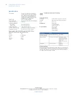
• Position the sensor to protect an area where an intruder is
most likely to walk across the detection pattern. (
Figure 1
).
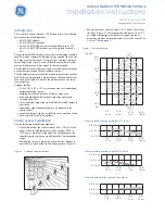
Figure 1. Overhead detection pattern
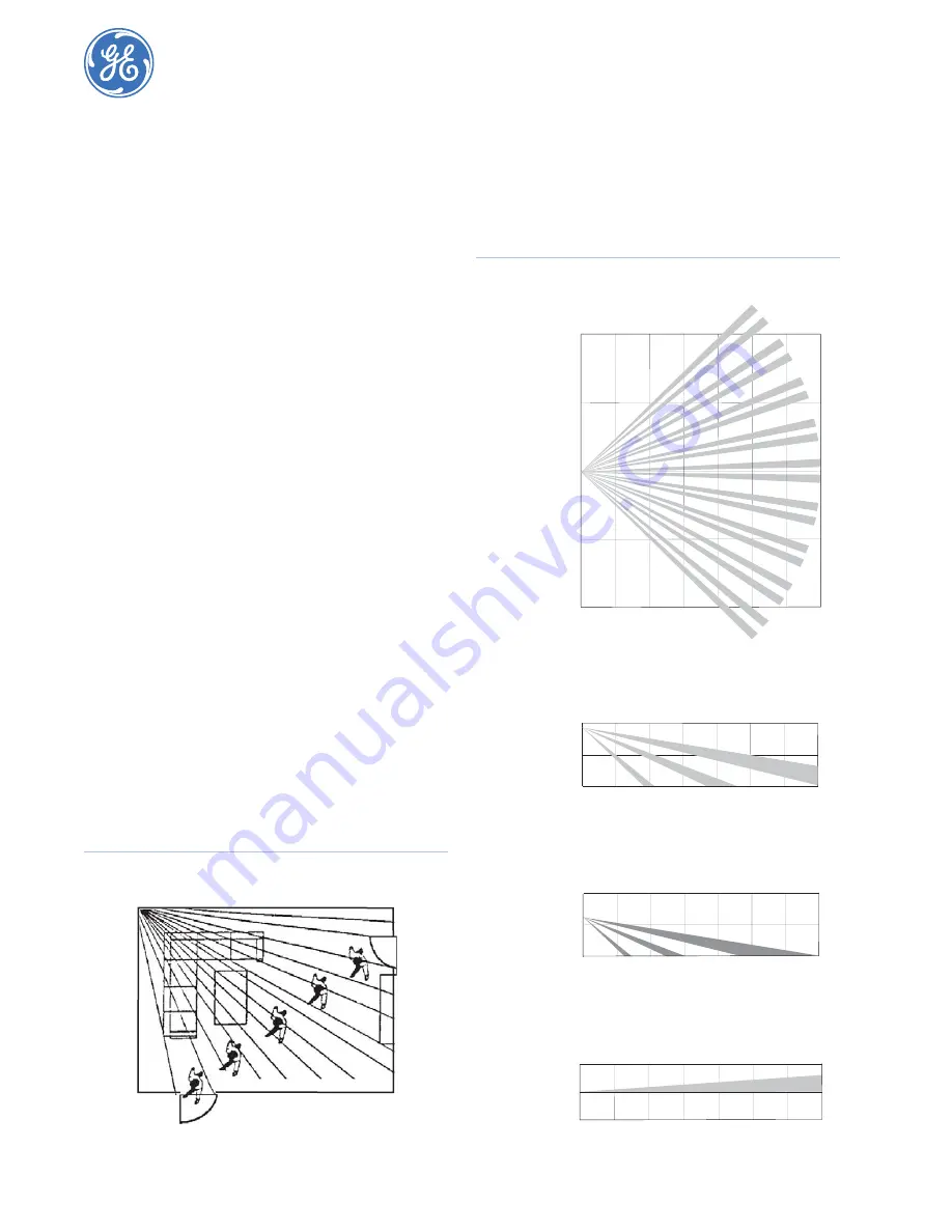
• Mount the sensor between 5 and 8 ft. (1.5 and 2.4 m) from
the floor (
Figure 2
). We recommend a height of 7.5 ft. (2.3
m). Higher mounting provides better range, and lower
mounting provides better protection close to the sensor. See
Pet alley lens
on page 3.
Figure 2. Detection pattern
Side view with mounting height of 7.5 ft. (2.3 m)
Top view
20 ft.
6 m
20 ft.
6 m
10 ft.
3 m
10 ft.
3 m
0 ft.
0 m
5 ft.
1.5 m
15 ft.
4.5 m
25 ft.
7.5 m
35 ft.
10.5 m
5 ft.
1.5 m
15 ft.
4.5 m
25 ft.
7.5 m
35 ft.
10.5 m
5 ft.
1.5 m
15 ft.
4.5 m
25 ft.
7.5 m
35 ft.
10.5 m
5 ft.
1.5 m
15 ft.
4.5 m
25 ft.
7.5 m
35 ft.
10.5 m
0 ft. (0 m)
0 ft. (0 m)
0 ft. (0 m)
8 ft. (2.4 m)
8 ft. (2.4 m)
4 ft. (1.2 m)
4 ft. (1.2 m)
Side view with mounting height of 5 ft. (1.5 m)
Side view with pet alley lens and flush mount
8 ft. (2.4 m)
4 ft. (1.2 m)


