background image

GE 

Sensing

OptiSonde™

General Eastern Chilled Mirror Hygrometer

User’s Manual

Summary of Contents for 1111H

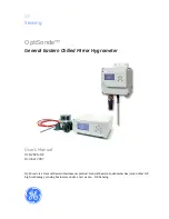
Page 1: ...GE Sensing OptiSonde General Eastern Chilled Mirror Hygrometer User s Manual ...

Page 2: ...stern Chilled Mirror Hygrometer User s Manual 910 282A GE October 2007 OptiSonde is a General Eastern Instruments product General Eastern Instruments has joined other GE high technology sensing businesses under a new name GE Sensing ...

Page 3: ... equipment was defective the warranty period is one year for general electronic failures of the instrument one year for mechanical failures of the sensor If GE Sensing determines that the equipment was damaged by misuse improper installation the use of unauthorized replacement parts or operating conditions outside the guidelines specified by GE Sensing the repairs are not covered under this warran...

Page 4: ...send your instrument to a service center it must be shipped prepaid to the authorized repair station indicated in the shipping instructions 3 Upon receipt GE Sensing will evaluate the instrument to determine the cause of the malfunction Then one of the following courses of action will then be taken If the damage is covered under the terms of the warranty the instrument will be repaired at no cost ...

Page 5: ...2 1 Benchtop Installation 2 1 Mounting the Benchtop 2 1 Wiring the Benchtop 2 1 Wall Mount Installation 2 3 Installing the Wall Mount 2 3 Wiring the Wall Mount 2 4 Input Power 2 6 Output Wiring 2 7 Analog Outputs 2 8 Alarm Outputs 2 8 Serial Output 2 10 Sensor Information 2 11 Sampling Lines 2 12 Ensuring Heat Transfer 2 12 Filter Requirements 2 13 Flow Rate 2 14 Sensor Installation 2 14 Model 111...

Page 6: ...nit 3 5 Supercooled Dew Points 3 6 Contamination 3 6 Mirror Flooding 3 8 Sample Line Maintenance 3 8 Pressure Effects 3 8 Chapter 4 Programming the OptiSonde Introduction 4 1 Programming Technique 4 2 Programmable Functions 4 3 Display 4 3 Analog Outputs 4 4 Alarms 4 5 Logging OptiSonde Data 4 6 OptiSonde Settings 4 9 Automatic Cleaning and Balance Function 4 10 Service Options 4 12 System Informa...

Page 7: ...Appears on the STATUS Display Line 5 7 Incorrect Dew Point Display 5 8 Balance Remains on the Status Line 5 9 No Analog Output 5 9 No Serial Output 5 9 Appendix A Specifications Performance A 1 Accuracy A 1 Measurement Ranges A 1 Response Time A 1 Update Time A 1 Functionality A 2 Alarms A 2 Operating Ranges A 2 Physical Bench Mount A 3 Physical Wall Mount A 3 Optional Accessories A 3 Appendix B H...

Page 8: ...rs Introduction D 1 Depression D 1 Measurement Range D 2 Comparing OptiSonde Sensors D 3 Appendix E Theory of Operation and Glossary Theory of Operation E 1 Hygrometer Function E 1 Hygrometer Calibration E 2 Other Hygrometer Applications E 3 The PACER Cycle E 4 Glossary E 5 ...

Page 9: ...Chapter 1 ...

Page 10: ...Features and Capabilities Introduction 1 1 Electronics Enclosure 1 2 The System 1 3 Sensors 1 4 ...

Page 11: ...lled mirror sensors to provide the following measurement ranges depending on the sensor selected one stage 45 depression 25 C and 1 ATM two stage 65 depression 25 C and 1 ATM depending on sensor as shown in Figure 1 1 below relative humidity from 0 02 to 100 moisture content from 0 9 ppmv to over 5 8 105 ppmv temperature from 100 to 100 C 148 F to 212 F Figure 1 1 Mirror Depressions at Various Tem...

Page 12: ... format for use in spreadsheets such as Excel or view screen captures in HyperTerminal Electronics Enclosure The OptiSonde is available in two configurations a benchtop model AC powered with DC option a wall mount unit housed in an IP65 enclosure See Chapter 2 Installation for details on how to mount the OptiSonde Front Panel The OptiSonde s front panel is shown in Figure 1 2 below The panel inclu...

Page 13: ...ort The OptiSonde uses the GE Sensing patented Programmable Automatic Contaminant Error Reduction PACER system for automated self cleaning and optics rebalancing Detailed specifications for the OptiSonde are given in Appendix A The System System Components A complete OptiSonde system consists of the following items Electronic monitor Temperature sensor Dew point sensor Maintenance kit Interconnect...

Page 14: ...ew point is to be determined In addition the OptiSonde is supplied with a temperature sensor GE Sensing provides the following sensors for various applications Dew Point Sensors Model 1111H Dew point single stage sensor with 1 M NDT Model 1111H GE Dew point single stage sensor with flange for duct mounting Model 1211H Two stage sensor high pressure and temperature Model D 2 Two stage sensor Temper...

Page 15: ...Chapter 2 ...

Page 16: ...Installation Introduction 2 1 Benchtop Installation 2 1 Wall Mount Installation 2 3 Output Wiring 2 7 Sensor Information 2 11 Sensor Installation 2 14 ...

Page 17: ... A metal stand on the bottom of the case can be unfolded to elevate the front of the instrument for easier viewing if desired Figure 2 1 OptiSonde Benchtop Dimensions Wiring the Benchtop Input Power The OptiSonde operates with input power from 100 to 240 VAC 10 See Figure 2 2 below The OptiSonde s voltage and frequency rating are listed on the product label A DC option offers a minimum of 18 to a ...

Page 18: ...nect the optional temperature sensor cable to the 9 pin temperature connector on the rear panel Other I O wiring connects to the appropriate terminal block Tighten all connector thumbscrews to prevent disconnections Figure 2 2 OptiSonde Benchtop Rear Panel Figure 2 3 OptiSonde DC Option Rear Panel ANALOG SHIELD RELAY SHIELD ANALOG SHIELD RELAY SHIELD ...

Page 19: ...designed to mount on a flat vertical surface such as a wall or panel To mount the wall mount version see Figure 2 4 and Figure 2 5 below Installing the Wall Mount Figure 2 4 OptiSonde Wall Mount Dimensions 8 17 208 10 48 266 4 49 114 2 86 73 7 80 198 4X Ø0 38 Ø10 Note units are inches mm ...

Page 20: ...rdware for the application such as with plasterboard or cement Wiring the Wall Mount Caution The wall mount unit meets IP65 rating for water ingress when tested with solid plugs In order to maintain this rating installation personnel must ensure that each of the two wiring ports use a single cable with a minimum diameter of 0 24 in 6 mm and a maximum diameter of 0 47 in 12 mm Recommended wire nuts...

Page 21: ...iring must be done in accordance with local codes Wire size cannot exceed 14 AWG 2 08 mm2 Insulation shall be stripped 6 mm prior to being inserted into the connection block Figure 2 6 Wall Mount Wiring Entrance Locations CHASSIS GROUND ANALOG INPUTS PIN 1 OUTA 2 OUTA 3 OUTB 4 OUTB FERRITE LOCAL SHOWN COVER ASSEMBLY NOT SHOWN RS232 PIN 1 TX 2 RX 3 RTN I O RELAY PIN 1 NO 2 NC 3 COMM A C POWER SHIEL...

Page 22: ... on the bottom of the unit Wiring of this terminal block is shown in Figure 2 7 below The external ground screw must connect the unit to protective earth using a wire that is sized equal to or great then the wire used for input power connections Grounding should be done in accordance with local codes Figure 2 7 Wall Mount AC Power Wiring A C POWER TERMINAL BLOCK 1 L LINE POWER CONNECTION 100 240VA...

Page 23: ...t in through the glands on the bottom of the unit and wired to the terminal blocks shown in Figure 2 8 below Terminal block screws must be torqued between 0 4 0 5 Nm Note Output programming is described in Chapter 4 Figure 2 8 Wall Mount Input Output Terminal Blocks ANALOG INPUTS PIN 1 OUTA 2 OUTA 3 OUTB 4 OUTB FERRITE RS232 PIN 1 TX 2 RX 3 RTN I O RELAY PIN 1 NO 2 NC 3 COMM A C POWER SHIELD EARTH...

Page 24: ...nects to the contacts of a 7 Amp Form C SPDT relay Make connections as follows For normally open contacts connect to NO and COMM For normally closed contacts connect to NC and COMM Any available parameter can be used to control an alarm relay by programming the parameter name and its threshold values An alarm can also be programmed to monitor the state of the Control PACER Balance or Service indic...

Page 25: ...the parameter is near the specified value The relay is activated when the parameter exceeds the upper limit and deactivated when the parameter goes below the lower limit Figure 2 9 Set Point Alarm Inner Band Alarm For the Inner Band alarm type the alarm relay activates whenever the parameter value is between the lower and upper limits Figure 2 10 Inner Band Alarm ...

Page 26: ...f the benchtop unit see Figure 2 2 on page 2 2 and inside the wall mount unit Figure 2 6 on page 2 5 The output provides RS 232C serial communications between the unit and a terminal or a PC running in terminal emulation mode The benchtop connector is a standard 9 pin D connector For connection to a serial device the wallmount cable is wired as shown in Figure 2 8 on page 2 7 The baud rate can be ...

Page 27: ...nstalling a sensor consider the following criteria Locate the sensor as close as is practical to the source of the gas to be measured to keep the sampling lines as short as possible This minimizes the system response time and reduces the error rate at low frost points due to sample line outgassing Caution The OptiSonde electronics and sensors are for General Purpose Locations only They are not for...

Page 28: ...g system should allow for periodic cleaning It may be helpful to install a tee and closing valve on the inlet side to permit the sensor to be shut off while the sampling lines are flushed At very low humidities even a trace amount of contamination can alter measured frost point so cleanliness is particularly important Ensuring Heat Transfer Be sure the sensor has an adequate heat sink when operati...

Page 29: ...the sample line s ambient temperature The simplest way to achieve this is to use heater tape either thermostatically controlled or continuously operating and sized to provide the required temperature rise At high temperatures use stainless steel tubing with adequate insulation to avoid hot and cold sections in the line and to avoid water absorption desorption cycling as the heater is thermostatica...

Page 30: ...l 1111H Sensor The Model 1111H is an open type sensor see Figure 2 12 below with 45 C depression capability at 25 C 1 ATM It can be threaded into standard pipe fittings or mounted in a type 0111D pressure boss which encloses it and adapts it for inch compression fittings When installing the sensor in the pressure boss remove the black aluminum sensor cover A second version the 1111H GE extends 9 i...

Page 31: ...e Figure 2 13 below For maximum thermal conductivity the base of the Model D 2 sensor should be coated with heat conducting grease When so installed on a surface suitable for dissipating heat the sensor will achieve its maximum rated depression See the Chilled Mirror Sensor Comparison Chart in Appendix D Figure 2 13 Model D 2 Sensor Model 1211H Sensor The Model 1211H is a two stage sensor with 65 ...

Page 32: ...responding sockets as shown in Figure 2 2 on page 2 2 for the benchtop unit or Figure 2 6 on page 2 5 for the wall mount unit The 1111H sensor can be mounted directly to the wall mount enclosure to facilitate room monitoring Ensure that the sensor or cable is fully inserted and the ring coupler fully hand tightened for reliable operation Tighten dome nut to 22 in lb 2 5 Nm to assure a proper seal ...

Page 33: ...Chapter 3 ...

Page 34: ...Operation Introduction 3 1 Normal Operation 3 1 Operating the OptiSonde 3 2 Status Line Indications 3 3 Sensor Balancing 3 5 Helpful Hints For Operating the Unit 3 5 ...

Page 35: ... wall mount unit For the benchtop unit switch the main power switch on the rear to ON I The OptiSonde begins its power up sequence which lasts about a minute The unit s software version is displayed on the initial screen Initializing Next the OptiSonde performs an AUTO or a PACER balance The PACER balance typically requires five to fifteen minutes depending on the sensor chosen and the humidity of...

Page 36: ...own in the upper right and the balance indicator is shown in the lower left Figure 3 1 Typical OptiSonde Display Screen To control the sensor press the ENT key If the OptiSonde keys are locked press the ESC key followed by the ENT key and then press the ESC key again The Function Control screen appears as shown in Figure 3 2 below Use the four arrow keys to select the desired function Figure 3 2 F...

Page 37: ...stable mirror temperature Service Req The sensor optics require service cleaning or adjustment Tracking The unit is responding to a changing dew point Control The unit is actively controlling the mirror temperature at a stable dew point Alarm The alarm has been activated Auto Cycle The Auto Cycle cleaning and balancing cycle is active PACER The PACER cleaning and balancing cycle is active Heating ...

Page 38: ... Data Field 2 Humidity Units Tdew C Temperature Units Tmp C Dry bulb Sound On Gas Molecular Weight of Gas 28 9645 typical for air Communication Parameters Baud rate 38 400 Serial Outputs Humidity Units Tdew C Humidity Units RH Temperature Units Tmp C Data Log COMM Status Stopped Interval 60 second Separator tab Parameters Td C Ta C RH Flags enabled Data Log FILE Status None Stopped Interval 60 sec...

Page 39: ... page 5 1 Helpful Hints For Operating the Unit Time response At dew points above 0 C the system stabilizes within a few minutes at a consistent dew layer The status Control is displayed when the system is stable and readings are valid When the system is operating at low frost points below 0 C extra care may be required when interpreting readings because of the longer response times of the system T...

Page 40: ...ation Mirror Cleanliness Proper operation of a condensation hygrometer depends on the condition of the mirror surface In general accuracy is reduced when contaminants accumulate on the mirror However the mirror does not have to be microscopically clean In fact the mirror performs best a few hours after cleaning when nucleation sites have formed On an unscratched freshly cleaned mirror there are re...

Page 41: ...ove the true dew point Because the measurement error increases gradually it often goes undetected To determine whether dissolved contaminants are affecting dew point measurement perform the following steps 1 Note the indicated dew point 2 Clean the mirror 3 Balance the detector by initiating a PACER cycle 4 Measure the dew point again If the new reading is lower than the first reading it is likely...

Page 42: ...minutes before the sensor dries out and valid readings can be obtained The drying process can be accelerated by heating the sensor Sample Line Maintenance Contaminated sample lines slow the unit s response time and can cause erroneous readings usually on the high side Clean the sample lines as often as necessary To determine the required cleaning frequency take dew point readings before and after ...

Page 43: ...Chapter 4 ...

Page 44: ...Programming the OptiSonde Introduction 4 1 Programming Technique 4 2 Programmable Functions 4 3 ...

Page 45: ...tings are selected from a list of choices others are entered as numeric or alphanumeric data using the keypad Table 4 1 Programming Functions Function Settings Display Select units for parameter display Outputs Select units and scaling test and trim values Alarms Alarm type and alarm limits Logs Selection of logging card or PC logs parameter choice units data format Settings Automatic balance soun...

Page 46: ...y to step through its available settings 4 For a particular setting press the ENT key to open the setting for editing If the setting uses a list of specific choices the T key and or S key are shown Press them to step through the choices Note To enter numeric data use the arrow keys to scroll to the appropriate column then use the S and T keys to scroll to the desired numeric value Note that certai...

Page 47: ... Dew frost point temperature in degrees Celsius Td F Dew frost point temperature in degrees Fahrenheit RH Percentage of relative humidity Ta C Temperature in degrees Celsius dry bulb Ta F Temperature in degrees Fahrenheit dry bulb e mbar Water vapor pressure in millibars Tw C Wet bulb temperature in degrees Celsius Tw F Wet bulb temperature in degrees Fahrenheit PPMv Parts per million by volume ΔT...

Page 48: ...ch output channel you will program A or B Units Choose the units for scaling the parameter on the selected channel See Table 4 2 on the previous page for the available units Type Choose the type of output 4 20 mA 0 20 mA Upper Set the parameter value that will produce full scale output span for the selected channel Enter a number Lower Set the parameter value that will produce zero output for the ...

Page 49: ...hen the OptiSonde is actively controlling mirror temperature Service Alarm activates when the Service indicator is activated PACER Alarm activates when the PACER or AUTO balance is active Table 4 4 Alarm Options Setting Description Available Options Status Enable or disable the alarm Off On Units Set the units for the parameter See Table 4 2 on page 4 3 Type Set the type of condition that will act...

Page 50: ...log on either File or Comm OptiSonde automatically closes the previous log 3 To enter logging parameters enter Units You can select any combination of the units available in Table 4 2 on page 4 3 for up to eight units Press ENT to confirm your selections 4 To select the logging interval enter Interval You can then enter the output interval in seconds up to 86400 Press ENT 5 To select the output fo...

Page 51: ...rt Enter Close to permanently stop and complete the log Only closed logs can be erased You can retain an internal File log in the SD transfer it to the PC or erase it To transfer a log to the PC enter Manage Transfer Then select the log from the list of logs and press ENT To erase a log from the SD enter Manage Erase Then select the log from the list of logs and press ENT The OptiSonde will displa...

Page 52: ...e log on internal SD card Comm log on PC Manage Internal or File logs only Handle individual logs Details displays file name interval and size Transfer transfer closed log to PC New Log set up new log Erase delete log from OptiSonde Units Set up to eight units to log See Table 4 2 on page 4 3 Interval Enter the output interval in seconds for Serial Mode All Enter a number up to 86400 Format Choose...

Page 53: ...ound Select whether the OptiSonde produces a sound when users press the keypad Off On Adjust Enter the offset values for the Dew Point Temperature and Filter parameters Enter the values by which the parameters will be offset Gas The molecular weight of the gas being analyzed The default value is the molecular weight of air 28 9645 g mole Enter a number Clock Enter the current time and date Enter t...

Page 54: ... 7 below explains the difference between the options Note The PACER function will provide more thorough cleaning than the AUTO function because it first develops a thick dew frost layer into which soluble contaminants dissolve When heated some of the contaminants are flash evaporated and the remaining residue accumulates in clusters resulting in the cleaning of much of the mirror s surface The PAC...

Page 55: ... Balance Menu and the Main Menu for the settings to take effect IMPORTANT For environments or a gas sample where the mirror accumulates contamination rapidly the use of an inline filter is recommended Lower flow rates will also reduce the accumulation of contaminants Cleaning and Balancing Options Table 4 8 Cleaning and Balancing Options Setting Description Available Options Type Select type of mi...

Page 56: ...ess to the Main Menu To unlock the keys press ESC ENT and ESC Press ESC again to reenter the Main Menu Table 4 9 Communication Parameter Options Setting Description Available Options Baud Set the baud rate to be compatible with the receiving device 1200 2400 4800 9600 19200 38400 57600 115 200 Note 38400 is the default value for PC communications Node ID Select Node ID number for PanaView transmis...

Page 57: ...Chapter 5 ...

Page 58: ...Maintenance Minor Maintenance of Sensor Optics 5 1 Field Replacement of Sensor Mirrors 5 5 Test and Calibration 5 7 Troubleshooting 5 7 ...

Page 59: ... increases and decreases in digital steps The bias screw adjusts the light signal received by the reference photodetector and is used as a coarse adjustment The automatic balance or PACER cycle discussed on page 1 6 electronically fine tunes the optical balance between the IR emitters and reference photodetectors In operation the position of the balance indicator will depend on the level of humidi...

Page 60: ...ton swab on the mirror in a circular motion spiral outwards to clean the mirror d Use a dry swab to dry and buff the mirror The mirror should be bright and shiny e Discard the used swabs IMPORTANT If the contamination is severe then solvents such as alcohol acetone or hexane may be used followed by a rinse of the cleaning solution then distilled water Be sure to dry and buff the mirror with a dry ...

Page 61: ...u are performing a coarse balance adjustment Figure 5 3 Balance Adjustment Screw Locations IMPORTANT This adjustment is made while the cap or cover is on the 1111H D2 sensors For the 1211 the adjustment is made with the cap removed In these cases the adjustment should not be made in sunlight bright incandescent or infrared light It might be useful to shade the sensor cavity with your hand or place...

Page 62: ...overshoot then it will stabilize assuming the sensor is exposed to constant humidity When a stable dew or frost layer is attained you will see the word Control in the lower left The OptiSonde is now reading the correct dew frost point and a stable dew or frost layer has been established When the OptiSonde is exposed to typical room humidity this process takes 5 6 minutes For very dry conditions th...

Page 63: ...with the copper and eventually pit the surface or form a copper sulfate coating The reflective surface may be gradually abraded by sharp dirt particles in the gas being measured The mirror surface may be accidentally scratched or gouged during use or cleaning If the sensor mirror has reacted with a corrosive material in the gas sample such as an acid or sulfur compound it should be replaced with a...

Page 64: ...4 Unscrew and discard the old mirror using a 3 16 inch 0 187 hex socket 5 Use a toothpick or similar tool to place a small amount of thermal compound in the hole supporting the mirror Caution Do not apply thermal compound to the mirror stem Do not use an amount large enough to leak out when the mirror is tightened Do not allow any compound to get on the mirror surface as it is very difficult to re...

Page 65: ...ability Troubleshooting The Display Doesn t Light Up 1 On the benchtop model check the POWER switch on the rear panel Make sure it s ON 2 Check the line cord Make sure both ends are plugged in and that it is plugged into a proper source of AC voltage 3 Check the power supply Make sure it is connected and has the proper output voltage 4 Check the fuse Make sure the proper fuse size is installed Mak...

Page 66: ...or refer to page 5 1 An alternative method for checking the accuracy of the unit s electronics is to use a precision resistance decade box in place of the platinum thermometer Wire the decade box to the unit s sensor connector as shown in Figure 5 4 below and verify that the resistance settings shown in the table produce the temperatures shown Figure 5 4 Using a Resistance Decade Box ...

Page 67: ...ct them and the unit will complete the PACER cycle after a short time 5 to 15 minutes The sensor bridge may be out of balance refer to page 5 1 No Analog Output If there is no analog output but the digital display indicates correctly check the analog output scaling No Serial Output Check the serial port programming for proper settings ...

Page 68: ...Appendix A ...

Page 69: ...Specifications Performance A 1 Functionality A 2 Physical Bench Mount A 3 Physical Wall Mount A 3 Optional Accessories A 3 ...

Page 70: ...0 09 F Repeatability 0 1 C 0 18 F Measurement Ranges Chilled Mirror Sensors available 1111H 1111H GE 1211H D 2 Range one stage 45 depression 25 C and 1 ATM two stage 65 depression 25 C and 1 ATM dew frost point depending on sensor used Temperature Sensor T 100E 100 C to 100 C 148 F to 212 F Recommended Sample Flow 0 5 to 2 5 scfh 0 25 to 1 25 L min Response Time Dew Frost Point Cooling Rate 1 5 C ...

Page 71: ...orm C SPDT 7 A 30 VDC resistive load Display 128 X 64 pixel monochrome LCD Power 100 240 VAC 10 50 60 Hz 18 minimum 32 maximum VDC benchtop only on special order Operating Ranges Dew Point Sensors Temperature 1111H 15 to 80 C D2 25 to 85 C 1211H 15 to 100 C Pressure 1111H 200 psig max D2 150 psig max 1211H 300 psig max Electronics Temperature 10 C to 60 C 14 F to 140 F Relative Humidity 85 maximum...

Page 72: ...2 4 cm Weight 3 lb 1 4 kg Environmental IP 20 Physical Wall Mount Dimensions 10 48 H 8 2 W 4 5 D 26 6 cm 20 8 cm 11 4 cm Weight 5 3 lb 2 4 kg Environmental IP 65 Optional Accessories PTFE GE Filter for 1111H GE PTFE FM 1 Rotameter BF12SS Inline filter Specifications subject to change without notice ...

Page 73: ...Appendix B ...

Page 74: ...Humidity Equations and Conversion Chart Introduction B 1 Vapor Pressure B 1 Humidity B 2 ...

Page 75: ...e C Vapor Pressure Saturation vapor pressure with respect to water is a function of temperature only and is given by the following B 1 Saturation vapor pressure with respect to ice requires a minor adjustment of the constants as given by the following B 2 In addition to yielding saturation vapor pressure as a function of ambient temperature the above equations also yield ambient vapor pressure as ...

Page 76: ... air according to the following B 4 Water vapor content expressed as parts per million by volume is given by the following B 5 Expressing water vapor content as parts per million by weight or mixing ratio requires multiplication of the above by the ratio of the molecular weight of water to that of air as given by the following B 6 See Figure B 1 on page B 3 for a graphical humidity conversion char...

Page 77: ...Humidity Equations and Conversion Chart B 3 October 2007 Figure B 1 Graphical Humidity Conversion Chart ...

Page 78: ...Appendix C ...

Page 79: ...Configuring the Serial Interface Wiring to a Personal Computer C 1 ...

Page 80: ...ial interface 2 Transmitted data TXD 3 Received data RXD 5 Signal ground GND To send the output of a benchtop OptiSonde to a personal computer use the cable arrangement shown in Figure C 1 below For a wall mount OptiSonde use the wiring shown in Figure C 2 on the next page Figure C 1 Wiring Diagram Benchtop OptiSonde to PC OptiSonde PC 9 Pin Female 9 Pin 3 2 5 3 2 5 TX RX GND ...

Page 81: ...October 2007 C 2 Configuring the Serial Interface Wiring to a Personal Computer cont Figure C 2 Wiring Diagram Wall Mount OptiSonde to PC RS232 PIN 1 TX 2 RX 3 RTN ...

Page 82: ...Appendix D ...

Page 83: ...Chilled Mirror Sensors Introduction D 1 Depression D 1 Measurement Range D 2 Comparing OptiSonde Sensors D 3 ...

Page 84: ...t the mirror block will eventually cool to its minimum temperature The difference between the temperatures of the mirror block and the sensor body when the mirror block is at this minimum temperature is defined as the depression capability of the sensor Depression capability is a function of how many stages the Peltier device has stacked in series Thus a two stage sensor typically has 60 C to 65 C...

Page 85: ...can be estimated by first estimating depression capability and then decreasing this range according to the minimum required differential For most gases other than air the effect on measurement range is negligible However gases such as hydrogen or helium which are more thermally conductive than air will result in a decrease of several degrees in the measurement range Measurement range will decrease...

Page 86: ...easurement Range at given ambient 1 atm at 25 C ambient at 25 C ambient at 25 C ambient Dew Frost Point 15 to 25 C 35 to 25 C 35 to 25 C RH equivalent 6 to 100 1 5 to 100 1 5 to 100 Functional Characteristics Power From OptiSonde From OptiSonde From OptiSonde Ambient Temperature Range 15 to 80 C 25 to 85 C 15 to 100 C Pressure Range psig 3 to 200 3 to 150 0 to 300 Auxiliary Cooling No No No Sensor...

Page 87: ...Appendix E ...

Page 88: ...Theory of Operation and Glossary Theory of Operation E 1 The PACER Cycle E 4 Glossary E 5 ...

Page 89: ...ted with a solid state infrared emitter IR A photodetector monitors the IR light reflected from the mirror The photodetector is fully illuminated when the mirror is clear of dew and it receives less light as dew forms A separate LED and photodetector pair are used as a known reference to compensate for any thermally induced changes in the OptiSonde components The photodetectors are arranged in an ...

Page 90: ...gainst their primary humidity standards A calibrated instrument can then be used as a transfer standard in local laboratories to calibrate lower echelon instruments Caution Field calibration is not recommended Hygrometers used as calibration standards must have the following characteristics The mirror thermometer must have suitable long term accuracy such as that obtained with a platinum resistanc...

Page 91: ...system cools and returns to the same dew point The GE Sensing OptiSonde condensation sensors cover a wide range of applications limited only by the heat pumping capabilities of the thermoelectrically cooled mirror At high dew points up to 100 C the sensor is limited by the thermal properties of the solid state OptiSonde components as well as the thermoelectric heat pump capacity In a typical appli...

Page 92: ...nants particularly for near ambient dew points The OptiSonde is equipped with the PACER cycle as well as AUTO balance as found on earlier models The user can choose which self cleaning and balancing routine to run depending on the severity of contamination The PACER cycle diagrammed in Figure E 2 below begins with a coalescence period during which the mirror is cooled well below the dew point of t...

Page 93: ...bility The temperature difference by which the chilled mirror can be lowered from the ambient temperature PACER GE Sensing patented Programmable Automatic Contaminant Error Reduction system which consolidates soluble contaminants to reduce their effect on system accuracy see The PACER Cycle on page E 4 Parameter A measured quantity available for display by the unit such as Dew Point in C Humidity ...

Page 94: ... OptiSonde 4 10 Communication Parameters OptiSonde 4 8 Contamination Gaseous Contaminants 3 7 Minimizing the Effects 3 8 Mirror Cleanliness 3 6 Particulate Matter 3 6 Water Soluble Contaminants 3 7 D Default Settings 3 4 Definitions E 5 Depression Capability D 1 E 5 Dew Point Sampling Lines 2 13 Supercooled 3 6 Display Balance Displayed 5 9 Incorrect Dew Point 5 8 Troubleshooting 5 7 E Electronics...

Page 95: ...e D 2 Ranges 1 1 Mirror Cleaning 5 1 Flooding 3 8 Mirror Cleaning and Balancing 5 1 O Operation Helpful Hints 3 5 Normal 3 1 OptiSonde 3 2 Theory of E 1 OptiSonde Alarms 4 5 Analog Outputs 4 3 Communication Parameters 4 8 Display Screen 3 2 Operation 3 2 Programmable Functions 4 3 Programming 4 1 OptiSonde Sensor Comparison D 3 Outer Band Alarm 2 10 Outputs 1 3 P PACER Cycle E 4 Definition E 5 Par...

Page 96: ...Troubleshooting 5 9 Wiring 2 10 Service Required 5 7 Set Point Alarm 2 9 Specifications Functional A 2 Optional Accessories A 3 Performance A 1 Physical Benchtop A 3 Physical Wall Mount A 3 Status Line Indications 3 3 Supercooled Dew Points 3 6 System Components 1 3 T Testing 5 7 Troubleshooting 5 7 Balance on Display 5 9 Service Required 5 7 Incorrect Dew Point Display 5 8 No Analog Output 5 9 No...

Page 97: ...USA 1100 Technology Park Drive Billerica MA 01821 4111 Web www gesensing com Ireland Sensing House Shannon Free Zone East Shannon County Clare ...

Reviews: