En-1
INSTALLATION MANUAL
PART NO. 9380228004
AIR CONDITIONER
OPTIONAL PARTS
External connect kit
For authorized service personnel only.
1. SAFETY PRECAUTIONS
WARNING
This mark indicates procedures which,
if improperly performed, might lead to
the death or serious injury of the user.
When installing each wire, please thoroughly read this
•
manual.
Before installation be sure that all sources of power have
•
been shut off. There is a danger of electric shock.
For External connect kit and locally purchased parts,
•
apply voltage indicated on specifications of parts.
Application of unspecified voltage may result failure or
malfunction of air conditioner.
CAUTION
This mark indicates procedures which,
if improperly performed, might possibly
result in personal harm to the user, or
damage to property.
Do not pull on the connectors with too much force.
•
2. ABOUT THE UNIT
2.1. General
This external connect kit is an adapter for connecting the
•
control PC board and the connected unit (local wiring) in
order to use external input function and external output
function of the outdoor unit.
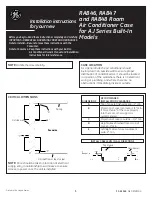
2.2. Accessories
The following installation parts are supplied.
•
Use them as required.
Contents
1. SAFETY PRECAUTIONS ................................................ 1
2. ABOUT THE UNIT ........................................................... 1
2.1. General ..................................................................... 1
2.2. Accessories .............................................................. 1
3. SETTING .......................................................................... 1
3.1. Control input setting.................................................. 1
3.2. Control output setting .....................................................2
4. CONNECTION METHOD TO OUTDOOR
CONTROL PC BOARD .................................................... 3
Name and shape
Q’ty
Description
Installation
manual
1
This manual
Binder
2
For fixing the wires.
Wire
1
For connecting to the
circuit for external input
and external output
3. SETTING
Connect the wire (External connect kit) and Connected
•
unit (local wiring). Refer to the following wiring method.
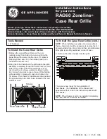
3.1. Control input setting
3.1.1
Wiring of connector
Input
Connector
Low noise mode
CN931
External input priority mode
CN932
Peak cut mode
CN933
Stop operation mode
CN934
* Make the distance from the PC board to the connected unit within
10m (33ft).
• Contact capacity : 24VDC or more, 10mA or more.
1
2
CN931
1
2
1
2
1
2
CN932
CN933
CN934
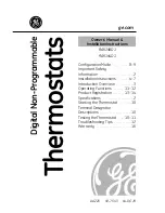
Circuit diagram example
Outdoor unit
control PC board
Connected unit
(Field supply)
Ex.) Switch
Wire
Signal
Connector
*10 m (33ft)
English
Français
Español
9380228004-01_IM.indb 1
24/9/2553 18:20:57