background image

English

Deutsch

Espa

ñol

Fran

ç

ais

Ital

iano

Portugu

ê

s

日 本 語

Póññêèé

÷–

Œƒ

Before Use

• INFORMATION......................................................................................................... E-2
• INSTALLATION ........................................................................................................ E-3

Usage

• PART NAMES AND FUNCTIONS............................................................................ E-4

Others

• OPTIONS.................................................................................................................. E-8
• MAIN SUPPORTED SIGNALS................................................................................. E-9
• SPECIFICATIONS.................................................................................................. E-10

Contents

Page

USER'S MANUAL

(Specification and Part Names)

WIDE PLASMA DISPLAY

P42VHA51W

P42HHA51W/P50XHA51W/P55XHA51W

P42HHA51A/P50XHA51A/P55XHA51A

Before using the display, read the User’s manual (1/2) and the User’s manual (2/2) carefully so that you know how to use the display
correctly.
Refer to this manual whenever questions or problems about operation arise.  Be sure to read and observe the safety precautions (see
the separate "Safety Precautions" manual).
Keep this manual where the user can see it easily.
* Installation and removal require special expertise.  Consult your product dealer for details.
* When "English" is selected at "Language" of the on-screen display, "colour" will be displayed but "color" is described in this manual.
* The residential warranty for "A model" is enclosed in accessories.
* The last digit of MODEL NO. (10 digit alphanumeric characters) indicated on the product means the body color indication alphabet or

the management number.

* The illustration of external appearance is for 42" model.

Please acknowledge some differences in the actual product of other models.

MHD01978_E.book  1 ページ  2005年10月7日 金曜日 午後5時18分

Summary of Contents for Plasmavision P42VHA51WS

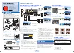
Page 1: ...ons or problems about operation arise Be sure to read and observe the safety precautions see the separate Safety Precautions manual Keep this manual where the user can see it easily Installation and removal require special expertise Consult your product dealer for details When English is selected at Language of the on screen display colour will be displayed but color is described in this manual Th...

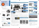
Page 2: ... When connecting the cord to the power input terminal RS232C input terminal attach one of these ferrite cores to the cord and the cable near the terminal Two small ferrite cores When connecting a cable to the external speaker output terminal attach one of these ferrite cores to the cable near the terminal CHECKING ACCESSORIES ATTACHING THE FERRITE CORES One power cable Two small ferrite cores One ...

Page 3: ...refore provide at least as much space as indicated below Make sure that the plasma display is installed in a location where the temperature can be maintained between 0 C and 40 C between 32 F and 104 F Never attempt to tilt the plasma display sideways or backward To prevent the power cord and other cables from being accidentally pulled make sure that they run along the wall or through corners To p...

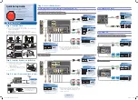
Page 4: ...Switches between picture input modes Volume button Volume button Adjusts the audio volume Wide screen selector button Switches the screen over to a desired wide screen ON OFF button Turns the power ON and OFF standby state Ambient Sensor Detects the brightness of external light Do not obstruct it Warning If the power indicator lamp flashes red or green this signifies that the display has developed...

Page 5: ...tor lamp will go out Power is still supplied to parts of the display even if the indicator lamp is off HDMI input terminal VIDEO5 INPUT HDMI Connect this terminal to the HDMI output terminal for DVD etc RS 232C terminal RS 232C This terminal is provided for you to control the display from the PC Connect it to the RS 232C terminal on the PC When connecting a cable attach a ferrite core to the cable...

Page 6: ...ut terminal VIDEO2 INPUT Connect this terminal to the S video output terminal of your VCR Audio3 input terminal AUDIO3 INPUT Audio2 input terminal AUDIO2 INPUT Audio1 input terminal AUDIO1 INPUT Connect this terminal to the audio output terminal of your VCR etc See the User s manual 2 2 for the selection of audio input for video input External speaker output terminal EXT SP Connect this terminal t...

Page 7: ...round Frame Ground RS 232C terminal RS 232C Pin No Signal 1 DCD Data Carrier Detect 2 RD Received Data 3 TD Transmit Data 4 DTR Data Terminal ready 5 GND Ground 6 DSR Data Set Ready 7 RTS Request To send 8 CTS Clear To Send 9 RI Ring Indication HDMI input terminal VIDEO5 INPUT HDMI Pin No Input signal Pin No Input signal 1 T M D S Data2 11 T M D S Clock Shield 2 T M D S Data2 Shield 12 T M D S Clo...

Page 8: ...er 1 set of 2 speakers P SP1000 for attaching to the display for 42 model 50 model P SP5010 for attaching to the display for 55 model P SP4200 for mounting on the speaker stands for 42 model P SP5010 for mounting on the speaker stands for 50 model 55 model Desktop Speaker Stand 1 set of 2 speaker stands P ST4200 for P SP4200 P ST5000 for P SP5010 Warning To prevent injury fire and electric shock a...

Page 9: ...l frequency Hz Signal 640 x 480 31 47 59 94 VGA 640 x 480 37 50 75 00 VGA 75 Hz 640 x 480 43 27 85 01 VGA 85 Hz 720 x 400 31 47 70 09 400 lines 800 x 600 37 88 60 32 SVGA 60 Hz 800 x 600 46 88 75 00 SVGA 75 Hz 800 x 600 53 67 85 06 SVGA 85 Hz 1024 x 768 48 36 60 00 XGA 60 Hz 1024 x 768 60 02 75 03 XGA 75 Hz 1024 x 768 68 68 84 99 XGA 85 Hz 1280 x 1024 63 98 60 02 SXGA 60 Hz 1280 x 1024 79 98 75 03...

Page 10: ... 75 Ω VIDEO3 VIDEO4 INPUT 3 RCA terminals Y 1 Vp p 75 Ω Component video input PB CB 0 7 Vp p 75 Ω PR CR 0 7 Vp p 75 Ω VIDEO5 INPUT HDMI input HDMI terminal HDMI type A connector PC input terminal RGB1 input mD sub 3 rows 15 pin Picture signal 0 7 Vp p 75 Ω Synchronization signal TTL level Audio terminals 2 audio input pin jacks L R 3 lines 500 mVrms at least 22 kΩ Control terminal RS 232C connecto...

Reviews: