


DS04-21381-1E
FUJITSU SEMICONDUCTOR
DATA SHEET
ASSP
Dual S
erial Input
PLL Frequency
Synthesizer
MB15F74UV
■
■
■
■
DESCRIPTION
The Fujitsu MB15F74UV is a serial input Phase Locked Loop (PLL) frequency synthesizer with a 4000 MHz and
a 2000 MHz prescalers. A 64/65 or a 128/129 for the 4000 MHz prescaler, and a 32/33 or a 64/65 for the
2000 MHz prescaler can be selected for the prescaler that enables pulse swallow operation.
The BiCMOS process is used, as a result a supply current is typically 9.0 mA at 3.0 V. The supply voltage range
is from 2.7 V to 3.6 V. A refined charge pump supplies well-balanced output current with 1.5 mA and 6 mA
selectable by serial date. The serial data format is the same as MB15F74UL. Fast locking is achieved for adopting
the new circuit.
MB15F74UV is in the small package (BCC18) which decreases a mount area of MB15F74UV about 50
%
com-
paring with the former BCC20 (for dual PLL) .
■
■
■
■
FEATURES
• High frequency operation
: RF synthesizer : 4000 MHz Max
: IF synthesizer : 2000 MHz Max
• Low power supply voltage
: V
CC
=
2.7 V to 3.6 V
• Ultra low power supply current : I
CC
=
9.0 mA Typ
(V
CC
=
3.0 V, Ta
=
+
25
°
C, SW
IF
=
SW
RF
=
0 in IF/RF locking state)
(Continued)
■
■
■
■
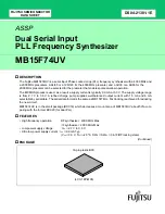
PACKAGE
18-pin plastic BCC
(LCC-18P-M05)