background image


Console Drawer (FD-1000AT) 

(for PC SERVER) 

User’s Manual 


Summary of Contents for FD-1000AT

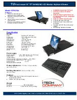
Page 1: ...Console Drawer FD 1000AT for PC SERVER User s Manual ...

Page 2: ...this device may not cause harmful Interference and 2 this device must accept any Interference received Including Interference that may cause undesired operation This Product is designed developed and manufactured as contemplated for general use including without limitation general office use personal use household use and ordinary industrial use but is not designed developed and manufactured as co...

Page 3: ...LES 12 Connecting Cables 12 Removing Cables 12 Connecting to Ports 13 OPERATION 14 Operating the Console Drawer 14 Adjusting the Monitor 17 Basic Adjustment Procedure 18 Menu Screen Display Example 18 Menu Description 19 Resolution and Refresh Rate 20 Using a Linux Operating System 21 Keyboard Operation 22 Pointing Device Operation 22 The Hot key and Reset Buttons 23 Using CRT KB Switcher 23 Stori...

Page 4: ...ii ...

Page 5: ...by ignoring this symbol the Console Drawer is operated incorrectly This logo indicates supplemental information comments or hints Text that is preceded by a number such as 1 indicates that the operation must be done in the order indicated Reference to important chapter titles and terminology are in brackets Packing List Make sure that the items in the following list were included in the shipping p...

Page 6: ...aged when unpacking 2 Remove the rubber stabilizer from the front left side of the Console Drawer The rubber stabilizer is inserted to prevent the Console Drawer from sliding when installing or moving it Be sure to keep it after finishing the installation for when it needs to be used again Rubber stabilizer removal diagram CAUTION ...

Page 7: ... Drawer Make sure that the rated voltage meets the specifications of this device Refer to Technical Specifications and the model plate on this device The power cable for the Console Drawer is specially certified Do not connect it to anyplace other than a grounded wall outlet Arrange the immediate area around the Console Drawer s power socket and the rack s power outlet so that the plug can be quic...

Page 8: ...ta cables connected to peripheral equipment Unplug the power plug from the grounded power outlet if there is a power outage Follow the instructions in the appropriate section in Operation when cleaning the server Keep this manual with the Console Drawer If you give the Console Drawer to a third party give them this manual also Do not use the Console Drawer as a foot rest or lean against it with it...

Page 9: ... Spacers will be at the back See the installing the guide rail diagram on page 6 1 Insert the rear spacer studs of the guide rails into the holes in the rear rack pillars Fasten each guide rail with two screws inserted from the outside of the pillar one into each of the top and bottom holes of the rear spacer 2 Extend the guide rails to reach the inside of the front rack pillar Fasten each guide r...

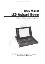
Page 10: ...6 Installing the Guide Rails diagram ...

Page 11: ...e Drawer does not slide easily into the guide rail or is heavy lift and insert it with two or more people 1 After installing the guide rails insert the Console Drawer into the front end of the guide rails 2 Push the Console Drawer in until it stops then fasten with two screws one on each side of the front of the Console Drawer Installing the Console Drawer diagram ...

Page 12: ...tric charges Only work on this device after checking that it has been electrically discharged Some metal edges may be sharp Be careful to not cut yourself To avoid damaging this device do not place foreign objects including metal objects water and or liquids inside it Also do not touch except as necessary To avoid damage only licensed engineers should install the 4 port KVM switch Philips screwdri...

Page 13: ... open space in the rear top panel making sure that the 4 port KVM switch s connectors face out from the rear of the Console Drawer 3 Reattach the KVM holder to the rear top panel with the four screws removed in step 1 Installation Method 1 4 port KVM switch Assembly Diagram viewed from the left rear ...

Page 14: ...he Installing Console Drawer operation on page 7 1 Remove the four screws that secure the KVM holder in place 2 Insert the 4 port switch into the open space in the rear top panel making sure that the 4 port KVM switch s connectors face out from the rear of the Console Drawer 3 Fasten the 4 port KVM switch in place with the four new screws inserted from underneath the rear panel 4 Reattach the KVM ...

Page 15: ...ft and right sides of the 4 port KVM switch Insert the 4 port KVM switch under the KVM holder between the two bent down flaps of the rear top panel making sure that the 4 port KVM switch s will face out from the rear of the Console Drawer Fasten it in place with the four screws removed in step 2 3 Reattach the rear top panel with 4 port KVM switch attached to the rear plate Comp using the ten scre...

Page 16: ... Cables 1 Unplug the power cords from the power outlets of all the equipment that is effected 2 Connect the keyboard cable mouse cable and the monitor cable to their respective pieces of equipment 3 Plug the power cable into the Console Drawer 4 Plug the power cable into a grounded power outlet Connecting cables to Console Drawer diagram Removing Cables Unplug the power cords from the power outlet...

Page 17: ...rts 1 Connect the keyboard cable to the KB port the mouse cable to the Mouse port and the monitor cable to the COMMON DISP port 2 Use the dedicated cable to connect the server keyboard port PS 2 and the mouse port PS 2 to the KB Mouse port 6 pin mini DIN 3 Connect the terminal monitor cable to the 1 DISP port 15 pin mini D SUB Connecting ports diagram If you are using a separate CRT KB switcher ra...

Page 18: ...s as pulling or pushing the slide module and opening and closing the LCD Operating the Console Drawer 1 If the rubber stabilizer has not been removed yet remove it now 2 Push down on the latch lever on the front left side of the Console Drawer Pull out the Console Drawer until it clicks Before pulling it out make sure that the two screws on the front of the Console Drawer are tightly fixed to the ...

Page 19: ... the slide module diagram 3 Push up on the LCD lock on the left side of the handle and then grasp the handle and open the top of the monitor 4 Turn on the power by pushing the POWER button Open the monitor completely ...

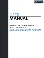
Page 20: ...16 Opening the LCD diagram ...

Page 21: ...n Push this button to adjust the monitor Button Push this button when selecting downward and to change values in a decreasing direction Button Push this button when selecting upward and to change values an increasing direction Button Push this button to select or enter things You can eliminate screen noise by adjusting the PHASE on the setting menu Be careful when applying a strong force to the eq...

Page 22: ...ustment screens with the button 4 Change setting values with the button and the button 5 Apply setting values and return to the menu screen with the button 6 Push the menu button to close the menu The menu button automatically closes if no button operations are done for a set time and are automatically set after the button is pressed Menu Screen Display Example ...

Page 23: ... Adjust the phase eliminate screen noise Clock Adjust the width of the display Auto Setup Adjusts automatically Language Select the language used for the menu Color Adjusts the color Special Press to change the settings shown below Factory Setting Return to factory default status DOS Mode Switch between 640 and 720 of the horizontal resolution in DOS mode Video Level Adjust the level of the input ...

Page 24: ...lution and Refresh Rate Resolution Horizontal frequency KHz Vertical frequency Hz Mode 31 47 60 0 37 86 72 0 600 480 37 5 75 0 37 9 60 0 48 1 72 0 800 600 46 9 75 0 48 4 60 0 56 5 70 0 1024 768 60 0 75 0 VESA ...

Page 25: ... INIT Switching to runlevel 3 INIT Sending processes the TERM signal press return to continue Follow the procedure listed below to reinstall X Windows so that it will start normally Startup the system using the installation CD then select the installation mode listed below to begin the installation Standard install mode Select Programmable up to MHz as the mode clock on the Select Video Card scree...

Page 26: ...ce twice or click the left button twice 1 The pointing device has been designed to be operated with one finger do not use it in the following ways 1 while wearing gloves 2 with a pen ballpoint pen or pencil etc 3 with two or more fingers 4 operating while something is placed on the operation surface 2 Normal operation may become impossible if the operation surface gets wet such as when there is hi...

Page 27: ...t when using various types of CRT controllers when setting up multiple servers Generally resolution and refresh rate vertical frequency are the same for all servers therefore just a set of one type of parameters supports these settings which are stored for the screen Displays on other servers are effected by correcting an on screen image that has shifted To correct shifted displays change the foll...

Page 28: ...e sure that the LCD lock catches 3 Push the locking springs on both sides of the slide rail and slide the Console Drawer into the rack Be sure the latch lever catches Be careful not to pinch your fingers or hands in the guide rails slide rails or the Console Drawer itself when storing the Console Drawer If the latch lever is not set the Console Drawer may slide out if the rack is moved We recommen...

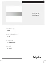
Page 29: ...25 Inserting the slide module diagram ...

Page 30: ...wer If liquids enter the interior of the Console Drawer it may result in malfunctions or damage Wipe the Console Drawer and monitor with a dry cloth If the dirt is excessive wipe it off with a soft cloth that has been thoroughly wrung out after being dipped in household cleanser diluted with water Remove dust with a soft brush Clean the keyboard and pointing device with a sterile cloth Lightly wip...

Page 31: ...m 3 2 the LCD are fully opened 485 mm x 1077 mm x 345 mm Weight 12 0 Kg Required Environment Operating Temperature 15 35 C Avoid condensation during use According to the server environment Monitor Panel monitor 15 TFT color LCD Resolution Max horizontal 1024 dots x vertical 768 line Pitch 0 297 x 0 297mm Refresh rate Max 75Hz Colors Max 16 777 216 dithering Brightness 250 cd m Connector mini D SUB...

Page 32: ...S layout European layout Number of keys Japanese layout 87 US layout 83 European layout 84 Connector mini DIN 6 pin Pointing Device Model Static Touch Pad Resolution 240 cpi counts inch Connector mini DIN 6 pin Button Number of buttons 3 ...

Page 33: ......

Page 34: ...rinted in Japan The contents of this manual may be modified for improvements without prior notice Fujitsu bears no responsibility for infringement of patent or other rights of third parties ascribable to the use of data in this manual Reprinting of this manual without permission is prohibited ...

Page 35: ...This manual is made of recycled paper 021220 ...

Reviews: