background image

Assembly Instructions

 SMARTCASE S520 

__________________________________________________________________________________________________________________________________________________________ 

Page 1 of 12 

V1.1 - 07/2019 

  www.fujitsu.com 


Assembly Instructions 


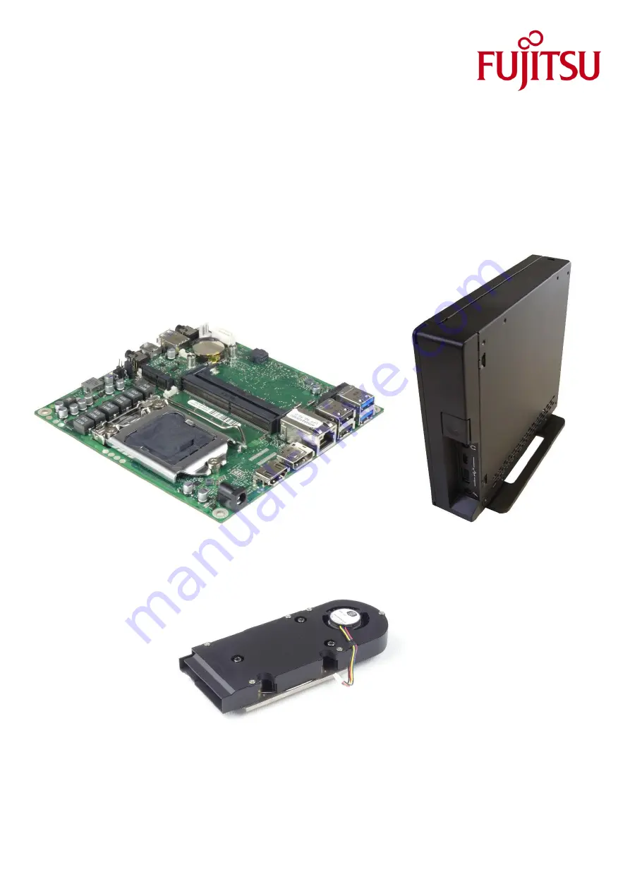
SMARTCASE S520 & D3654-B / D3664-B 


________________________________________________________________________________________________________ 
 

Summary of Contents for D3654-B

Page 1: ...________________________________________________________________________________________________ Page 1 of 12 V1 1 07 2019 www fujitsu com Assembly Instructions SMARTCASE S520 D3654 B D3664 B ________________________________________________________________________________________________________ ...

Page 2: ...____ Page 2 of 12 V1 1 07 2019 www fujitsu com Table of Contents Step 1 Preparing the Chassis 3 Step 2 Inserting additional Modules Memory M 2 4 Step 3 Mainboard Assembly 6 Step 4 Installing the Heatsink 7 Step 5 Installing optional HDD Tray updated 8 Step 6 Optional Components 9 Installing WLAN Antennas 9 Speaker Assembly 10 Step 7 Closing the Chassis updated 11 Step 8 Adding Stands 12 ...

Page 3: ...o hands by putting some pressure on your thumbs to push the cover reverse Remove top cover and unpack the accessories Remove the tape transportation lock of the thermal pad carefully Note Thermal pad has been implemented as running change may not be included in first shipments Rear Cover Chassis kit content Please install the additional EMI gasket in the position as marked in the chassis Note This...

Page 4: ...ide edges only Do not stick a barcode onto any modules The following procedure is recommended in order to ensure secure electrical contact 1 First insert the lower memory angular and pay attention to the notch 2 Remove the memory again completely from the DIMM socket 3 Insert memory again 4 Press down the memory until it clicks into place 5 Do not press in the middle of the memory but press down o...

Page 5: ...hile paying attention to the coding notch Both modules as shown in the picture have to be touched on the outside edges only For the M 2 Key M SSD and M 2 Key E WLAN BT the assembly nuts and screws are pre installed Recommended torque for the M 2 screw is 0 2Nm and 0 3Nm for the nut Processor assembly First open the CPU socket and remove the socket protection Then insert the CPU Consider the mechan...

Page 6: ...ards the front I O holes red circle 2 Move the mainboard carefully down to the final position Take care the thermal pad1 and the EMI gasket1 stay in the right position 1 May not be included in the first chassis shipments due to running change Push down the mainboard carefully while the four mounting holes fit onto the chassis nuts Assemble only the yellow marked mounting screws if you want to inst...

Page 7: ...heatsink solution Before assembling the mainboard into the chassis it is recommended to install the optional onboard components like cooler RAM M 2 etc Active Heatsink Note Recommended mounting torque for heatsink screws 0 6Nm max 0 8Nm Active heatsink positioning Heatsink must be positioned according to picture Hold the heatsink with one hand so that it doesn t tilt while installing the screws As...

Page 8: ...dated Plug the SATA and power cable to the onboard connectors Then insert the HDD Tray carefully into the chassis and assemble the four screws M3x4 5 red marked NOTE Consider the optionally installed WLAN antenna cables when installing the HDD Tray The protection foil of the HDD Tray has to be below the chassis metal blue arrow to protect the cables when closing the chassis Install the SSD into th...

Page 9: ...pectively gray Please note that the plastic front bezel has to be removed first Push the antenna cables completely through the opening in the housing and pay attention to the antenna cable notch see red circles Carefully install the WLAN antennas The metal plate must not be bent Insert the black antenna cable in the hooks see red circles and then plug the black antenna cable to socket 1 of the M 2...

Page 10: ...______ Page 10 of 12 V1 1 07 2019 www fujitsu com Speaker Assembly Please note that the plastic front bezel has to be removed first Insert speaker into rubber Install speaker rubber in front bezel Speaker cable lead to mainboard via appropriate chassis aperture Re assemble plastic front bezel carefully and install speaker connector to mainboard Speaker Rubber Speaker speaker location ...

Page 11: ... fujitsu com Step 7 Closing the Chassis updated Slide the cover on top of the chassis while pushing it forward Some pressure may be required Note As the mainboard D3664 B provides an additional USB type C port a different rear chassis wall is required for SMARTCASE S520 This chassis wall K1056 B520 is included in the D3664 B mainboard delivery kit Close the chassis rear cover using the screws incl...

Page 12: ...f 12 V1 1 07 2019 www fujitsu com Step 8 Adding Stands The chassis kit includes a desk stand for vertical use and four rubber feet for horizontal use They desk stand can be fixed by plastic clips in addition there are screws included for more secure stand assembly Assemble the two M2 5x6 0 screws with 0 25Nm for the desk stand blue or the four screws M3x5 for the rubber feet red Bottom of the chas...

Reviews: