background image

ࡕ࠺࡞

2724/2737/2742/2616/2624/2642

ޓޓޓ

2724/2737/2742/2616/2624/2642

19R-272A2

19R-273A2

19R-273B2

19R-274A2

19R-274B2

19R-261A2

19R-262A2

19R-264A2

19R-264B2

C120-E665-04XA

J

E

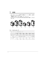
Summary of Contents for 19R-261A2

Page 1: ...ࡕ 2724 2737 2742 2616 2624 2642 ޓޓޓ 2724 2737 2742 2616 2624 2642 19R 272A2 19R 273A2 19R 273B2 19R 274A2 19R 274B2 19R 261A2 19R 262A2 19R 264A2 19R 264B2 C120 E665 04XA J E ...

Page 2: ...て 本製品は 一般事務用 パーソナル用 家庭用 通常の産業用等の一般的用途を想定して設計 製造されて いるものであり 原子力施設における核反応制御 航空機自動飛行制御 航空交通管制 大量輸送システム における運行制御 生命維持のための医療器具 兵器システムにおけるミサイル発射制御など 極めて高度 な安全性が要求され 仮に当該安全性が確保されない場合 直接生命 身体に対する重大な危険性を伴う用 途 以下 ハイセイフティ用途 という に使用されるよう設計 製造されたものではございません お客 様は 当該ハイセイフティ用途に要する安全性を確保する措置を施すことなく 本製品を使用しないでくだ さい ハイセイフティ用途に使用される場合は 弊社担当営業員までご相談ください 当社のドキュメントには 外国為替および外国貿易管理法 に基づく特定技術が含まれていることがありま す 特定技術が含まれている場合は...

Page 3: ...した記号は 警告 注意を促す内容であることを告げるもので す 記号の中やその脇には 具体的な警告内容が示されています で示した記号は してはいけない行為 禁止行為 であることを告 げるものです 記号の中やその脇には 具体的な禁止内容が示されて います で示した記号は 必ず従っていただく内容であることを告げるもの です 記号の中やその脇には 具体的な指示内容が示されています 記号 意味 お使いになる際の注意点や してはいけないことを記述しています 必ずお読みください ハードウェアやソフトウェアを正しく動作させるために必要なことが 書いてあります 必ずお読みください 参照ページや参照マニュアルを示しています 製品名称 本文中の表記 19 インチラック モデル 2724 2737 2742 2616 2624 2642 19R 272A2 19R 273A2 19R 273B2 19R 274A...

Page 4: ...4 改版記録表 注 変更箇所は最新版の項番を示しています ただし アスタリスク の付いている項番は 旧版の項番を示します 版数 日 付 変更箇所 変更種別 注 変更内容 01 2011 11 02 2012 01 全体 モデル 2737 を追加 03 2012 08 4 13 追加 コンセントボックスの取り付け手順 を追加 04 2012 12 1 2 変更 搭載可能装置を変更 ...

Page 5: ... 4 ラックの設置 21 3 5 ラックの連結 23 4 ラック設置後の取り扱いについて 29 4 1 ケージナット取り付け 取り外し手順 29 4 2 コアラットの取り付け 取り外し手順 33 4 3 扉回転軸位置の変更手順 35 4 4 汎用テーブル 固定式 の取り付け手順 52 4 5 汎用テーブル 可動式 の取り付け手順 58 4 6 ノートパソコン格納テーブルの取り付け手順 64 4 7 ケーブルホルダーの取り付け手順 69 4 8 ブランクパネルの取り付け手順 74 4 9 サイドケーブルダクトの取り付け手順 75 4 10スタビライザー L 字型 の取り付け手順 81 4 11スタビライザー 引出型 の取り付け手順 82 4 12耐震キットの取り付け手順 85 4 13コンセントボックスの取り付け手順 87 ...

Page 6: ...の外観イメージを以下 に示します 1 1 ラインナップ 本ラックのラインナップは次の表のとおりです モデル 2724 モデル 2737 モデル 2742 モデル 2616 モデル 2624 モデル 2642 収容ユニット数 24U 37U 42U 16U 24U 42U 型名 基本ラック 19R 272A2 19R 273A2 19R 274A2 19R 261A2 19R 262A2 19R 264A2 増設ラック 19R 273B2 19R 274B2 19R 264B2 サイズ 幅 奥行 高さ mm 700 1050 1200 700 1050 1800 700 1050 2000 600 1050 845 600 1050 1200 600 1050 2000 ...

Page 7: ...1 概要 7 J 1 2 搭載可能装置 本ラックには以下の富士通製品を搭載できます 注 PC サーバ UNIX サーバ ストレージシステム 基幹 IA サーバ ネットワーク製品 注 詳細は弊社ホームページ http jp fujitsu com にてご確認いただくか あるいは弊社 担当営業員までご相談ください ...

Page 8: ... 搭載装置 ラックの固定など の地震対策が必要です 床の強度が弱い場所に設置しないでください 最大搭載時の最大質量は 1000kg 程度になるため 強度が弱い床では床が抜け る可能性があります ラックシステムの正常な稼動 保守を容易にするために 設置エリアを確保し てください ラックの上または近くに 花びん 植木鉢 コップ などの水の入った容器 金属物を置かないでください 故障 火災 感電の原因となります 湿気 ほこり 油煙の多い場所 通気性の悪い場所 火気のある場所に置かな いでください 故障 火災 感電の原因となります 直射日光の当たる場所や 暖房器具の近くなど 高温になる場所には設置しな いでください また 10 未満の低温になる場所には 設置しないでください 故障の原因になります ラックの開口部 通風孔など をふさがないでください 通風孔をふさぐと内部に熱がこもり故障や火災の原因と...

Page 9: ...レ ベーターの積載質量が搬入する装置質量以上でも使用できることを事前に確認してくだ さい 装置搬入時は 転倒防止のためラック高さ方向の半分よりも下を押してください 本ラックに搭載する装置によっては 重心位置が高い場合があります また 側面からは押さないでください 転倒するおそれがあります 前扉の中央付近 吸気口部分を押すと扉が変形するおそれがありますので 扉の角を押 してください ラック搭載の本体製品を寒い場所から暖かい部屋へ搬入すると 製品内部が結露しま す 1時間あたりの温度上昇が 15 を超えないように室温調整を行い 結露を発生させな いようにしてください 結露の発生に関しては 次の表を参考にしてください 室内温度 備考 10 15 20 25 30 35 40 相対湿度 20 7 5 3 1 5 9 13 例 温度 25 で湿度 60 の場合 装置が 17 以下のとき 結 露します...

Page 10: ...運用時の留意事項 通気 保守エリアの確保 ラックを設置するときは 放熱と保守用にスペースが必要です 次のスペースを確保してください 1 ラックの外形寸法は各ラックの仕様による 2 上部通線エリアを使用する場合 ただし 16U ラックと 24U ラックは除く OO OO OO OO OO OO OO OO OO OO OO OO OO OO OO 7 OO 7 OO 7 OO 7 ࠢ೨㕙ⷞ ࠢ 㕙ⷞ ࠢ೨㕙 ㅢ ޔ ࠛ ࠕ ...

Page 11: ...あるレベリングフットで本ラックを支えるように設置しま す レベリングフットを調整し ラックが水平になるようにしてください キャスターは床面から 1 2mm 浮かした状態にしてください ラックはボルト等で床 スラブ に固定してください 固定しない場合 加速度 2 5m s2 250gal を超える地震が発生したとき ラックが 転倒するおそれがあります ラックが転倒した場合 死亡または重症を負うおそれがあります またラック内の 機器や周囲の物が破損するおそれがあります モデル名 耐震キット型名 基本ラック用 増設ラック用 2724 2737 2742 19R 27ST1 19R 27ST2 2616 2624 2642 19R 26ST1 19R 26ST2 ᮏయ ୖ㠃 ࣞ ࣜࣥࢢ ࣇࢵࢺ ࣕࢫࢱ ࣇࣟࣥࢺ ...

Page 12: ...い 固定設置 スタビライザーによる設置を しない状態でラック内部の装置を引き出すと ラックが転倒するおそれがあり ます ブランクパネルを装置未搭載部に取り付けないと 排気が吸気面に回り込んで 装置の故障や寿命を短縮するおそれがあります ラックの前扉 後扉は取り外さないでください 扉は質量があるため 倒れた り 落下したりしてケガの原因となることがあります 取り外す必要が生じた場合には 弊社担当保守員にご連絡ください ラック設置後にラックを移動する場合は 必ず弊社担当営業員または担当保守 員にご連絡ください 不用意に移動すると ラックが損傷することがあります ラックに登ったり寄りかかったりしないでください 転倒などの事故のおそれ があります ࡉ ࡦࠢࡄࡀ 7 ࡉ ࡦࠢࡄࡀ 7 ࡉ ࡦࠢࡄࡀ 7 㧔ขࠅઃߌᓟߩ ᘒ㧕 วࡇࡦ ᣇⓣ ਅᣇⓣ ਛᄩⓣ ...

Page 13: ...ご注意ください 注 2 扉のハンドルロックにはキー操作が必要です 項目 仕様 品名 19 インチラック モデル 2724 基本ラック 型名 19R 272A2 外観 黒色塗装 前後扉パンチングメタル仕様 収容ユニット数 24U サイズ WxDxH mm 700 1050 1200 搭載最大質量 kg ラック総質量 571kg 注 1 搭載総質量 480kg ラック本体除く ラック本体 91kg 扉の開口率 80 付属品 ラックに取り付けて出荷されるもの 前扉 後扉 サイドカバー 2 枚組 別梱包で添付品として出荷されるもの ラック扉用キー 2 個 注 2 ケーブルホルダー 前用 6 個 ケーブルホルダー 後用 6 個 M5 サイズのサラネジ コアラット 各 12 個 ケーブルホルダー用 ケージナット工具 取扱説明書 CD 1式 ...

Page 14: ...ック 型名 19R 273A2 19R 273B2 外観 黒色塗装 前後扉パンチングメタル仕様 収容 ユニット数 37U サイズ WxDxH mm 700 1050 1800 搭載最大 質量 kg ラック総質量 864kg 注 1 搭載総質量 740kg ラック本体除く ラック本体 124kg ラック総質量 840kg 注 1 搭載総質量 740kg ラック本体除く ラック本体 100kg 扉の開口率 80 付属品 ラックに取り付けて出荷されるもの 前扉 後扉 サイドカバー 2 枚組 前扉 後扉 注 2 別梱包で添付品として出荷されるもの ラック扉用キー 2 個 注 3 ケーブルホルダー 前用 8 個 ケーブルホルダー 後用 8 個 M5 サイズのサラネジ コアラット 各 16 個 ケーブルホルダー用 ケージナット工具 保護ブッシュ 2 個 取扱説明書 CD 1式 ラック扉用キー 2 個 ...

Page 15: ...2 増設ラック 型名 19R 274A2 19R 274B2 外観 黒色塗装 前後扉パンチングメタル仕様 収容 ユニット数 42U サイズ WxDxH mm 700 1050 2000 搭載最大 質量 kg ラック総質量 969kg 注 1 搭載総質量 840kg ラック本体除く ラック本体 129kg ラック総質量 943kg 注 1 搭載総質量 840kg ラック本体除く ラック本体 103kg 扉の開口率 80 付属品 ラックに取り付けて出荷されるもの 前扉 後扉 サイドカバー 2 枚組 前扉 後扉 注 2 別梱包で添付品として出荷されるもの ラック扉用キー 2 個 注 3 ケーブルホルダー 前用 10 個 ケーブルホルダー 後用 10 個 M5 サイズのサラネジ コアラット 各 20 個 ケーブルホルダー用 ケージナット工具 保護ブッシュ 2 個 取扱説明書 CD 1式 ラック扉用...

Page 16: ...ラック モデル 2616 基本ラック 型名 19R 261A2 外観 黒色塗装 前後扉パンチングメタル仕様 収容ユニット数 16U サイズ WxDxH mm 600 1050 845 搭載最大質量 kg ラック総質量 387kg 注 1 搭載総質量 320kg ラック本体除く ラック本体 67kg 扉の開口率 75 付属品 ラックに取り付けて出荷されるもの 前扉 後扉 サイドカバー 2 枚組 別梱包で添付品として出荷されるもの ラック扉用キー 2 個 注 2 ケーブルホルダー 前用 4 個 ケーブルホルダー 後用 4 個 M5 サイズのサラネジ コアラット 各 8 個 ケーブルホルダー用 ケージナット工具 取扱説明書 CD 1式 ...

Page 17: ...19 インチラック モデル 2624 基本ラック 型名 19R 262A2 外観 黒色塗装 前後扉パンチングメタル仕様 収容ユニット数 24U サイズ WxDxH mm 600 1050 1200 搭載最大質量 kg ラック総質量 559kg 注 1 搭載総質量 480kg ラック本体除く ラック本体 79kg 扉の開口率 80 付属品 ラックに取り付けて出荷されるもの 前扉 後扉 サイドカバー 2 枚組 別梱包で添付品として出荷されるもの ラック扉用キー 2 個 注 2 ケーブルホルダー 前用 6 個 ケーブルホルダー 後用 6 個 M5 サイズのサラネジ コアラット 各 12 個 ケーブルホルダー用 ケージナット工具 取扱説明書 CD 1式 ...

Page 18: ...ク 型名 19R 264A2 19R 264B2 外観 黒色塗装 前後扉パンチングメタル仕様 収容 ユニット数 42U サイズ WxDxH mm 600 1050 2000 搭載最大 質量 kg ラック総質量 954kg 注 1 搭載総質量 840kg ラック本体除く ラック本体 114kg ラック総質量 928kg 注 1 搭載総質量 840kg ラック本体除く ラック本体 88kg 扉の開口率 80 付属品 ラックに取り付けて出荷されるもの 前扉 後扉 サイドカバー 2 枚組 前扉 後扉 注 2 別梱包で添付品として出荷されるもの ラック扉用キー 2 個 注 3 ケーブルホルダー 前用 10 個 ケーブルホルダー 後用 10 個 M5 サイズのサラネジ コアラット 各 20 個 ケーブルホルダー用 ケージナット工具 保護ブッシュ 2 個 取扱説明書 CD 1式 ラック扉用キー 2 個 ...

Page 19: ...3 ラックの構成と設置 19 J 3 2 前扉の開き方 1 扉用キーを回し解除します ハンドルを手前に引きます 注意 前扉を閉めるときは 搭載装置を完全に固定したあとに行ってください 地震が発生した場合 装置が飛び出し破損するおそれがあります ...

Page 20: ...20 3 3 後扉の開き方 1 扉用キーを回し解除します ラックハンドルを手前に引き上げ 矢印の方向にハンドルを回転し 手前に引きま す ...

Page 21: ...する場合 3 4 2 加速度 10m s2 1000gal までの地震に耐えられる設置 方法 と同じ方法で設置 してください 2 ラックを固定設置しない場合 転倒防止用スタビライザーを取り付けて設置してください 注 スタビライザーは装置保守時のラック転倒防止対策として取り付けます 固定 設置しない場合は必ずスタビライザーを取り付けて設置してください スタビライザーはオプションです 本ラックにはスタビライザーは添付されていません ラックへの取り付け形態は以下のとおりです 取り付け後の状態を考慮して適切なスタビ ライザーを選択してください スタビライザー L 字型 ラック前面取り付け 従来のラックに添付されていたスタ ビライザーと同等のものです 注 従来のラックのスタビライザーは本ラックに取り付けできません スタビライザー 引出型 ラック底面取り付け ラック底面にスタビライザー本体を 収納可能...

Page 22: ...た固定 ラック周囲 前後 左右 に耐震キット オプションのため別途手配が必要 を取 り付け 耐震キットの穴を利用してスラブ 建屋床面 に固定します 2 レベルフットを使用した固定 ラックのレベルフット底面にあいているサイズ M20 深さ 17mm のネジ穴を使用し てスラブ 建屋床面 に固定します ラックを固定設置しない場合は上記いずれかのスタビライザーを手配し 必ず 取り付けてください 取り付けない状態でラック内部の装置を引き出すと ラックが転倒するおそれがあります ೨㕙ψ ࡏ ᡰᩇ ࡈ ࡓ ࡌ ࡈ ࡈ ࠕࠢ ࠬࡈࡠࠕ ࡌ ࡈ ࠍ ߒߚ ቯᣇᑼߩ 㔡ࠠ ขࠅઃߌࠗࡔ ࠫ ...

Page 23: ...部連結ネジ M12 呼び 19 なお 高所での作業が必要ですので 脚立をご準備ください ラックの連結を行う場合は サーバ本体および周辺装置の電源を切り 電源 ケーブルをコンセントから取り外してください 感電したり機器が故障するおそれがあります ラックの連結を行う場合は 必ず 2 人以上で行ってください ケガの原因となります ラック上部で行う作業の際 脚立の上に乗る場合があります 落下にご注意ください ラックの連結を行うとき ラックに足を載せないでください 品 名 数 量 備考 下部連結金具 2 上部連結金具 2 奥行き方向連結パッキン 1 長さ 880mm 高さ方向連結パッキン 1 2 長さ 1000mm 高さ方向連結パッキン 2 2 長さ モデル 2737 650mm モデル 2742 2642 860mm M6 コアラット 8 下部連結用 M6 サラネジ 8 下部連結用 M12 六角ボ...

Page 24: ...状態であることを確認してください 2 トップカバー固定ネジを取り外し サイドカバーを取り外します 連結側となる右側前後のトップカバーを固定している M12 ネジ 2 本を外します サイドカバーを固定しているネジ 10 本を外して サイドカバーを取り外します 注 トップカバー部の作業は高所作業となりますので注意してください またその 際 ラックに足を載せるなどの行為は大変危険ですので 絶対に行わないでく ださい サイドカバーの質量は約 13kg ありますので取り外しの際は注意してください ここで取り外したサイドカバーネジは あとで使用しますので紛失しないように ご注意ください ࡀࠫ ࡊࠞࡃ ࠨࠗ ࠞࡃ ࠨࠗ ࠞࡃ ࡀࠫ ...

Page 25: ...順については 4 2 コアラットの取り付け 取り外し手 順 を参照してください 4 連結パッキンを貼り付けます 既設ラック右側前後 H フレームに高さ方向連結パッキン 1 と高さ方向連結パッキ ン 2 を貼り付けてください どちらを上側に貼り付けてもかまいません 貼り付ける位置は 高さ方向連結パッキン貼付位置詳細図を参照してください 既設ラック上部右側の D フレームに奥行き方向連結パッキンを貼り付けてくださ い 貼り付ける位置は 奥行き方向連結パッキン貼付位置詳細図を参照してください ๓㠃 㠃 ࣇࣞ 0 ࢥ ࣛࢵࢺ ࣇࣞ 0 ࢥ ࣛࢵࢺ 㹂ࣇࣞ 㹆ࣇࣞ 㧗ࡉ᪉ྥ㐃 ࣃࢵ ࣥ ዟ ࡁ᪉ྥ㐃 ࣃࢵ ࣥ 㧗ࡉ᪉ྥ㐃 ࣃࢵ ࣥ ヲ ࣇࣞ 㧗ࡉ᪉ྥ㐃 ࣃࢵ ࣥ ዟ ࡁ᪉ྥ㐃 ࣃࢵ ࣥ ヲ ࣇࣞ ዟ ࡁ᪉ྥ㐃 ࣃࢵ ࣥ ...

Page 26: ...作業となりますので注意してください またその 際 ラックに足を載せるなどの行為は大変危険ですので 絶対に行わないでく ださい ラック前面の連結側となる H フレーム 正面から見て左側 の下部に M6 コアラッ トを取り付けます ラック背面の連結側となる H フレーム 背面から見て右側 の下部に M6 コアラッ トを取り付けます コアラットの取り付け手順については 4 2 コアラットの取り付け 取り外し手 順 を参照してください 6 既設ラックと増設ラックの高さを合わせます 既設ラックの横に増設ラックを並べ 増設ラックのレベルフットを調節し 既設 ラックと高さを合わせます ࡈ ࡓ ࠦࠕ 㧴ࡈ ࡓ ࡀࠫ ࡊࠞࡃ ࠦࠕ ...

Page 27: ...は高所作業となりますので注意してください またその 際 ラックに足を載せるなどの行為は大変危険ですので 絶対に行わないでく ださい 既設ラックと増設ラックを合わせる際に連結パッキンが飛び出る 中に入るな どした場合は 指で引っ張る 押し込むなどにより調整してください 手順 3 および手順 5 の作業にて ラック前後の H フレームに取り付けた M6 コア ラットを利用して 下部連結金具を M6 サラネジで固定してください 仮止めしていた上部連結金具固定用 M12 六角ボルトを本締めしてください 注 トップカバー部の作業は高所作業となりますので注意してください またその 際 ラックに足を載せるなどの行為は大変危険ですので 絶対に行わないでく ださい ୖ㒊㐃 㔠ල 0 භゅ ࣝࢺ ୗ㒊㐃 㔠ල 0 ࢧࣛࢿࢪ ࣞ ࣝࣇࢵࢺ ...

Page 28: ...カバーを取り付けます 既設ラックから取り外したサイドカバーを既設ラックから取り外したサイドカバー 固定ネジ 10 本で取り付けます 注 サイドカバーの質量は約 13kg ありますので取り付けの際は注意してください 9 既設 増設ラックの前後の扉を取り付けます 最後に 前後の扉を取り付けて ラックの連結作業は終了です 前後扉の取り付け手順については 4 3 扉回転軸位置の変更手順 を参照してくだ さい ࢧ ࢻ ࣂ ࢧ ࢻ ࣂ ࢿࢪ ...

Page 29: ...いて この章では ラック設置後の取り扱いについて説明します 4 1 ケージナット取り付け 取り外し手順 4 1 1 取り付け手順 1 ケージナットをラック内側より取り付けます ケージナットの一方の爪 を ラックのケージナット取り付け穴に引っ掛けます 図は下側に引っ掛けた場合をあらわしています 2 ケージナット工具先端の爪をケージナット取り付け穴の手前から挿入し ケージナットのもう一方の爪に嵌合させます ケージナット ケージナット工具 外観 ケージナット工具 工具先端爪部の方向 ...

Page 30: ...挿入して 工具の先端に近 い位置を指でつかみ ケージナットの爪を押し込みます 工具あるいはマイナスドライバを押し下げる前に ナットの爪とラック柱の間 に工具の先端あるいはマイナスドライバの先端が完全に押し込まれていること を確認してください 押し込みが不十分な場合 工具あるいはマイナスドライ バの先端が外れ ケガの原因となることがあります ケージナットがラック内に落ちないようテープ等で養生してください 手で保 持する場合はケージナットの左右を持つようにしてください 挿入方向 矢印 方向 に押す 手前 矢印方向 に引く 押し込む方 工具をつかむ位置 工具先端爪部の方向 ...

Page 31: ...いて 31 J 注意 2 工具を押し下げて取り外します ケージナットを落とさないよう注意してください 増設 移設作業時にも本工具が必要となりますので 大切に保管してください マイナスドライバを使った手順 注意 指定位置より先端をつかまないでください 押し込み時に指がラックに当たり ケガをする原因になります ケージナットがラック内に落ちないようテープ等で養生してください 手で保 持する場合はケージナットの左右を持つようにしてください ...

Page 32: ...32 1 マイナスドライバの先端をケージナットの爪とラック柱の間に挿入して ケージナットの爪に押し込みます 2 マイナスドライバを押し下げて取り外します ...

Page 33: ...取り扱いについて 33 J 4 2 コアラットの取り付け 取り外し手順 4 2 1 取り付け手順 1 コアラットをアルミフレームの溝に の方向に差込み後 の方向に回転 させてください 回転させる際にペン先や先の細いマイナスドライバなどを利用すると作業しやすく なります 2 コアラットがアルミフレームの溝の中で斜めになっていないことを確認し てください コアラットのネジ部が溝の外から見えるか注意してください ࣝ ࣇࣞ 㠃 ...

Page 34: ...34 4 2 2 取り外し手順 1 コアラットをアルミフレームの溝の中で の方向に押して の方向に回 転させてください 回転させる際にペン先や先の細いマイナスドライバなどを利用すると作業しやすく なります 2 コアラットを の方向に引っ張って外してください 取り外す際にペン先や先の細いマイナスドライバなどを利用すると作業しやすくな ります ࣝ ࣇࣞ 㠃 ...

Page 35: ...必ず再使用します 余剰は発生しません またラックに予備部 品は添付されていませんのでご注意願います 部品の取り外し 取り付けにある 程度のカが必要な場合があります 作業にあたってはご注意願います 以下の作業には プラスドライバ 2 番 3 番 トルクドライバ 2 番ビット 必須では ありません ケージナット工具 六角レンチ 呼び 3 呼び 4 ボックスレンチ 呼び 7 後扉の作業時のみに必要 などの工具が必要です 4 3 1 前扉の軸位置変更手順 1 ラックから前扉を取り外します 扉を約 90 開けます 扉を上に持ち上げ ラック本体側ヒンジから扉側ヒンジ ピン を抜いて 扉を横にずらして取り外します 注 扉の取り付け 取り外しの際に 扉とラックの隙間に指などを挟まないように 注意してください 前扉のヒンジ用切り欠き部には開閉角度規制用曲げがあるため 扉を横にずら して外しにくい場合がありま...

Page 36: ...4 2737 2742 2616 2624 の場合 M6 ネジを外して 上下のロック受けを外し M6 コアラットを取り外してくだ さい モデル 2642 の場合 M5 サラネジを外して 上下のロック受けを外し M5 コアラットを取り外して ください コアラットの取り外し手順については 4 2 コアラットの取り付け 取り外し手 順 を参照してください 取り外した部品およびネジ類は後ほど使用しますので 紛失しないように注意し てください 注 M6 六角穴付き止めネジを緩めると ヒンジ用バーナットは落ちる可能性があ りますので注意してください ࡕ ࡕ ࡀࠫ ࡠ ࠢฃߌ ࠦࠕ ࡀࠫ ᧄ ࡅࡦࠫ ⷺⓣઃ߈ᱛ ࡀࠫ ࡅࡦࠫ ࡃ ࡕ ࠨ ࡀࠫ ࡠ ࠢฃߌ ࠦࠕ ...

Page 37: ...コアラットを入れてください モデル 2724 2737 2742 2616 2624 の場合 M6 コアラットを入れます モデル 2642 の場合 M5 コアラットを入れます コアラットの取り付け手順については 4 2 コアラットの取り付け 取り外し手 順 を参照してください ヒンジ用バーナットをアルミフレームの溝に入れる際は中で回転させてくださ い ヒンジ用バーナットは M6 六角穴付き止めネジのセンター位置をアルミフレーム のポンチに合わせてください M5コアラットおよびM6コアラットはネジ穴のセンター位置をアルミフレームの ポンチに合わせてください ࠦࠕ ࠦࠕ ⷺⓣઃ߈ᱛ ࡀࠫ ࡅࡦࠫ ࡃ ࡕ ࡕ ࡕ ࠬࠤ ࡐࡦ ࠬࠤ ࡐࡦ ࡅࡦࠫ ࡃ ⷺⓣઃ߈ᱛ ࡀࠫ ᢿ㕙 ࠬࠤ ࡐࡦ ...

Page 38: ... 上下フレームに本体側ヒ ンジを M6 ネジで取り付けてください フレーム上下にコアラットを利用してロック受けを取り付けます モデル 2724 2737 2742 2616 2624 の場合 M6 ネジで固定します モデル 2642 の場合 M5 ネジで固定します 上下ロック受けにパッキンがついていることを確認してください 上側ロック 上側にパッキンがついていること 下側ロック パッキンが金具の下側についていること ࡕ ࠨ ࡀࠫ ࡠ ࠢฃߌ ࡄ ࠠࡦ ࡕ ࡕ ࡀࠫ ࡠ ࠢฃߌ ࡄ ࠠࡦ ࡀࠫ ᧄ ࡅࡦࠫ ...

Page 39: ...側ヒンジおよびドアバーを取り外します M5 六角穴付きボルトを外してドア側ヒンジを取り外してください M4 ネジを外してレールガイドと上側および下側ドアバーを取り外してください ドアバーからレールガイドを外してください 上下のドアバーを外す際はバーを矢印 の向きに回転させて取り外してくださ い レールガイドはドアバーから外す際 図 のように折り曲げます ࢻ ഃࣄࣥࢪ 0 භゅ ࡁ ࣝࢺ ࣞ ࣝ ࢻ 0 ࢿࢪ ୖഃࢻ ࣂ ୗഃࢻ ࣂ ᢡࡾ ࡆࡿ ࣞ ࣝ ࢻ ...

Page 40: ...ハンドル本体の向きを反転させるためハンドルを前扉から取り外します 13mm 長 タッピンネジと 25mm 長 タッピンネジを外し ハンドルを取り外して ください 注 化粧パネルはハンドル本体と別部品となっております タッピンネジを外すと 落ちることがあるため注意してください 取り外した部品やネジ類は後で使用しますので紛失しないようにご注意くださ い OO㐳 ࡇࡦࡀࠫ OO㐳 ࡇࡦࡀࠫ OO㐳 ࡇࡦࡀࠫ ൻ ࡄࡀ ࡂࡦ ᧄ ᐔࡢ ࠪࡖ ォⷙ ㇱ ...

Page 41: ...ジでハンドルを取り付けてください 回転規制部材はギヤ部が上になるように取り付けます 向きを間違わないように してください 手順 6 で取り外した箇所と同じ長さのタッピンネジを使用してください 違う長 さのネジで締め付けた場合 部品を壊すことがあります 注 タッピンネジはトルクドライバーを使用し 1 0N m の締め付けトルクで締め 付けてください トルクドライバーが無い場合 きつく締めないよう注意して ください 締めすぎた場合 ハンドル部分が壊れることがあります PP㛗 ࢱࢵࣆࣥࢿࢪ PP㛗 ࢱࢵࣆࣥࢿࢪ PP㛗 ࢱࢵࣆࣥࢿࢪ ࣃࢿࣝ ࣁࣥࢻࣝᮏయ ᖹ ࢵࢩࣕ ᅇ つไ㒊ᮦ ...

Page 42: ...取り付けてください ドアバーにレールガイドを取り付けてください M12 ネジでレールガイドと上側および下側ドアバーを取り付けてください ドア用ヒンジをドア本体板金にまっすぐに突き当ててください 上下のドアバーを取り付ける際はバーを斜めに傾けた状態から の向きに回転さ せて取り付けてください レールガイドはドアバーから外す際 図 のように折り曲げます ࠅᦛߍࠆ ࠕ ࡅࡦࠫ ⷺⓣઃ߈ࡏ ࡀࠫ ࠕࡃ ਅ ࠕࡃ ࠟࠗ ࠬࠤ ࠬࠤ ࠕ ࡅࡦࠫߩ 㕙ߣ 㕙ࠍ ࠕᧄ ߩ ߦ ߞߔߋ ߒߞ߆ࠅߣ ߈ᒰߡࠆ ...

Page 43: ... 90 開いた状態で 扉を横にずらしてラック本体側ヒンジに扉側ヒンジ ピン を差し込んでください 注 扉の取り付け 取り外しの際に 扉とラックの隙間に指などを挟まないように 注意してください 前扉のヒンジ用切り欠き部には開閉角度規制用曲げがあるため 扉を入れにくい 場合があります 扉側ヒンジ ピン が上下とも確実に本体側ヒンジに差し込まれていることを確 認してください 以上で 前扉の回転軸位置の変更作業は終了です ᮏయഃࣄࣥࢪ ᡬഃࣄࣥࢪ ࣄࣥࢪ ษࡾḞࡁ㒊 㛤㛢ゅᗘつไ ࡆ ...

Page 44: ...にくい場合があります 2 ラック本体側の金具類を取り外します M6 ネジを外して上下の本体側ヒンジを取り外します M6 六角穴付き止めネジを外して上下のヒンジ用バーナットを外してください 中央付近のロック受けを取り外し コアラットを取り外してください モデル 2724 2737 2742 2616 2624 の場合 M6 ネジを外して 中央付近のロック受けを外し M6 コアラットを取り外して ください モデル 2642 の場合 M5 サラネジを外して 中央付近のロック受けを外し M5 コアラットを取り外 してください コアラットの取り外し手順については 4 2 コアラットの取り付け 取り外し手 順 を参照してください 取り外した部品およびネジ類は後ほど使用しますので 紛失しないように注意し てください ᮏయഃࣄࣥࢪ ᡬഃࣄࣥࢪ ࣄࣥࢪ ษࡾḞࡁ㒊 㛤㛢ゅᗘつไ ࡆ ...

Page 45: ...4 ラック設置後の取り扱いについて 45 J 注 M6 六角穴付き止めネジを緩めると ヒンジ用バーナットは落ちる可能性があ りますので注意してください ࡕ ࡕ ࡀࠫ ࡠ ࠢฃߌ ࠦࠕ ࡀࠫ ᧄ ࡅࡦࠫ ⷺⓣઃ߈ᱛ ࡀࠫ ࡅࡦࠫ ࡃ ࡕ ࠨ ࡀࠫ ࡠ ࠢฃߌ ࠦࠕ ...

Page 46: ...い モデル 2724 2737 2742 2616 2624 の場合 M6 コアラットを入れます モデル 2642 の場合 M5 コアラットを入れます コアラットの取り付け手順については 4 2 コアラットの取り付け 取り外し手 順 を参照してください ヒンジ用バーナットをアルミフレームの溝に入れる際は中で回転させてくださ い ヒンジ用バーナットは M6 六角穴付き止めネジのセンター位置をアルミフレーム のポンチに合わせてください M5コアラットおよびM6コアラットはネジ穴のセンター位置をアルミフレームの ポンチにあわせてください ࠦࠕ ࠦࠕ ⷺⓣઃ߈ᱛ ࡀࠫ ࡅࡦࠫ ࡃ ࡕ ࡕ ࡐࡦ ࡕ ࡐࡦ ࠬࠤ ࡐࡦ ࠬࠤ ࡐࡦ ࡅࡦࠫ ࡃ ⷺⓣઃ߈ᱛ ࡀࠫ ᢿ㕙 ࠬࠤ ࡐࡦ ...

Page 47: ...7 J 4 本体側ヒンジおよびロック受けを取り付けます 3 の手順で取り付けたヒンジ用バーナットを利用して H フレームに本体側ヒン ジを M6 ネジで取り付けてください フレーム中央付近にコアラットを利用してロック受けを取り付けます モデル 2724 2737 2742 2616 2624 の場合 M6 ネジで固定します モデル 2642 の場合 M5 ネジで固定します ࡕ ࡀࠫ ࡠ ࠢฃߌ ࡕ ࡕ ࡀࠫ ࡠ ࠢฃߌ ࡀࠫ ᧄ ࡅࡦࠫ ...

Page 48: ...48 5 ドア側ヒンジおよびハンドルブランクを取り外します M5 六角穴付きボルトを外してドア側ヒンジを取り外してください M4 フランジ付き六角ナットを外してハンドルブランクを取り外してください ࢻ ഃࣄࣥࢪ 0 භゅ ࡁ ࣝࢺ ࣁࣥࢻࣝࣈࣛࣥࢡ 0 ࣇࣛࣥࢪ ࡁභゅࢼࢵࢺ ...

Page 49: ...6 ハンドルを取り外します M6 フランジ付き六角ボルトとタッピンネジを外し ハンドル本体 回転規制部 材 ロック金具を取り外してください 注 取手部分はハンドル本体と別部品となっております タッピンネジを外すと落 ちることがあるため注意してください 取り外した部品やネジ類は後で使用しますので紛失しないようにご注意くださ い ࢱࢵࣆࣥࢿࢪ ࢱࢵࣆࣥࢿࢪ 0 ࣇࣛࣥࢪ ࡁභゅ ࣝࢺ ࣁࣥࢻࣝᮏయ ࣟࢵࢡ㔠ල ᅇ つไ㒊ᮦ ࣁࣥࢻࣝᅛᐃ ᶞ ྲྀࡗᡭ㒊 ...

Page 50: ...回転させて取り付けてください 向 きを間違わないように注意してください 8 ドア側ヒンジおよびハンドルブランクを取り付けます M5 六角穴付きボルトでドア側ヒンジを取り付けてください M4 フランジ付き六角ナットでハンドルブランクを取り付けてください ドア用ヒンジをドア本体板金にまっすぐに突き当ててください ォⷙ ㇱ ࠡࡗ ᄌᦝ ࡇࡦࡀࠫ ࡇࡦࡀࠫ ࡈ ࡦࠫઃ߈ ⷺࡏ ࡂࡦ ᧄ ࡠ ࠢ ౕ ォⷙ ㇱ ࡂࡦ ቯ ᮸ ขᚻㇱ ࠬࠤ q ォߐߖࠆ ࠬࠤ ࢻ ഃࣄࣥࢪ 0 භゅ ࡁ ࣝࢺ ࣁࣥࢻࣝࣈࣛࣥࢡ 0 ࣇࣛࣥࢪ ࡁභゅࢼࢵࢺ ࢫࢣ ࣝ ࢻ ࣄࣥࢪࡢୖ㠃 ഃ㠃ࢆ ࢻ ᮏయࡢᯈ㔠 ࡲࡗࡍࡄ ࡋࡗ ࡾ ࡁᙜ ࡿ ...

Page 51: ... 90 開いた状態で 扉を横にずらしてラック本体側ヒンジに扉側ヒン ジ ピン を差し込んでください 注 扉の取り付け 取り外しの際に 扉とラックの隙間に指などを挟まないように 注意してください 後扉のヒンジ用切り欠き部には開閉角度規制用曲げがあるため 扉を入れにくい 場合があります 扉側ヒンジ ピン が上下とも確実に本体側ヒンジに差し込まれていることを確 認してください 以上で 後扉の回転軸位置の変更作業は終了です ᮏయഃࣄࣥࢪ ᡬഃࣄࣥࢪ ࣄࣥࢪ ษࡾḞࡁ㒊 㛤㛢ゅᗘつไ ࡆ ...

Page 52: ...り付ける 2 リヤブラケットを取り付ける 3 テーブルを取り付ける 4 4 1 ケージナットの取り付け ケージナットをラックの柱 前後 に取り付けます ケージナットの取り付け方法につい ては 4 1 ケージナット取り付け 取り外し手順 を参照してください 1 前扉を開け 前側のラックの柱に M6 ケージナットを取り付けます 取り付け位置はテーブル搭載位置 1U の高さ のロケーション線間にある角穴 3ヶの上下 2ヶ所 左右合計 4ヶ所となります 汎用テーブル 固定式 型名 19R 26TR1 構成品 数量 テーブル 1 リヤブラケット L 1 リヤブラケット R 1 M6 ケージナット 8 M6 ボルト 4 M6 ネジ 8 ベルト 2 取付手順書 1 ᦚ 8 ๓ഃ ࣟࢣ ࢩࣙࣥ ࣛࢵࢡࡢᰕ 0 ࢣ ࢪࢼࢵࢺ ...

Page 53: ...位置が高さ方向でずれないようにして ください 4 4 2 リヤブラケットの取り付けとテーブルの仮置き 1 4 4 1 ケージナットの取り付け 手順 2 で取り付けた後側の M6 ケージ ナットを利用して リヤブラケット R とリヤブラケット L をラックの柱 に仮固定します 固定には M6 ネジを使用します 次の手順 2 で リヤブラケット L とリヤブラケット R にテーブルを載せます テー ブルを載せた際に落下しない程度に仮固定してください リヤブラケット L リヤブラケット R の取り付け向きに注意してください ᚋഃ ᦚ 8 ࣛࢵࢡࡢᰕ ࣟࢣ ࢩࣙࣥ 0 ࢣ ࢪࢼࢵࢺ 0 ࢣ ࢪࢼࢵࢺ 0 ࢣ ࢪࢼࢵࢺ 0 ࢿࢪ 0 ࢿࢪ ࣜࣖࣈࣛࢣࢵࢺ㹐 ࣜࣖࣈࣛࢣࢵࢺ㹊 ࣛࢵࢡࡢᰕ ...

Page 54: ...4 1 ケージナットの取り付け 手順 2 で取り付けた M6 ケージナットの直上の角穴に差し込み 角穴下面に載せ てください 後ろ側は手順 1 にて取り付けたリヤブラケット L リヤブラケット R の上に載せて ください 3 仮置き用曲げを差し込んだ角穴が左右で同じ高さであるか確認してくださ い 仮置き状態ですので テーブルの上に物を載せるなどの荷重がかかる行為はしな いでください 0 ࢣ ࢪࢼࢵࢺ ࢸ ࣈࣝ ௬ ࡁ ࡆ ௬ ࡁ ࡆࢆᕪࡋ ࡴゅ ...

Page 55: ...けた M6 ケージナット に M6 ネジを使ってテーブルを固定します リヤブラケット L リヤブラケット R がテーブルを載せても落下しないか 確認 してから作業をしてください テーブルを仮置きする際 前側は仮置き用曲げが角穴に対して十分差し込まれ確 実にテーブルが載るようにしてください また 後側はリヤブラケット L リヤ ブラケット R にテーブルが確実に載るようにしてください なお テーブルを固定するまでは支える手を離さないようにしてください ࢸ ࣈࣝ ࣜࣖࣈࣛࢣࢵࢺ㹊 ࣜࣖࣈࣛࢣࢵࢺ㹐 0 ࢿࢪ 0 ࢣ ࢪࢼࢵࢺ ௬ ࡁ ࡆ ...

Page 56: ... R をテーブルにしっかりと押し付け 隙間が ないようにして固定してください B C 方向 リヤブラケット L リヤブラケット R をしっかり押し付けられない場合は 印の M6 ネジを少し緩めてから固定してください 3 M6 ネジを本締めして 4 4 2 リヤブラケットの取り付けとテーブルの仮 置き 手順 1 にて仮固定していたリヤブラケット L リヤブラケット R をラックの柱に固定してください ࠤ ࡉࡗ ޓ หߓ ᢿ㕙 ቯߦ ߔࠆ ࡗࡉ ࠤ 4ߩࡀࠫⓣ ࡉ ࡗࡉ ࠤ 4 ᓟࠃࠅ㧝 ߩࡀࠫⓣ ᓟࠃࠅ㧟 ߩࡀࠫⓣ ࡉ ࠢߩᩇ ࠢߩᩇ ࡗࡉ ࠤ 㧸 ࡗࡉ ࠤ 㧾 ࡏ ࡗࡉ ࠤ 㧾 ࡉ ࡀࠫ ࣛࢵࢡࡢᰕ ࣜࣖࣈࣛࢣࢵࢺ㹐 ࣜࣖࣈࣛࢣࢵࢺ㹊 0 ࢿࢪ ࣜࣖࣈࣛࢣࢵࢺ㹐 ...

Page 57: ...4 ラック設置後の取り扱いについて 57 J 4 すべての M6 ネジ M6 ボルトが締められていることを確認してくださ い テーブルが下部の U スペース搭載を侵していないことを確認してください 5 必要に応じてラックの柱に固定している M6 ネジを緩め 再調整をしてく ださい ୗ㒊ᦚ 8ࢫ ࢫ ࣟࢣ ࢩࣙࣥ ௨ୗ ࡽ ࡇ ...

Page 58: ...表参照 がすべて揃っていることを確認します また必要な工具類を準備します プラスドライバ 3 番 ケージナット工具 汎用テーブル 可動式 の取り付けは 以下の手順で行います 1 ケージナットを取り付ける 2 リヤブラケットを取り付ける 3 テーブルを取り付ける 汎用テーブル 可動式 型名 19R 26TR2 品 名 数 量 テーブル 1 リヤブラケット L 1 リヤブラケット R 1 M6 ケージナット 8 M5 ケージナット 2 M6 ネジ 12 ベルト 2 取付手順書 1 ...

Page 59: ...ナットの取り付け位置はテーブル搭載位置 1U の高さ のロケーション 線間にある角穴 3ヶの真ん中 1ヶ所 左右合計 2ヶ所となります M6 ケージナットの取り付け位置はテーブル搭載位置 1U の高さ のロケーション 線間にある角穴 3ヶの上下 2ヶ所 左右合計 4ヶ所となります 2 後扉を開け 後側のラックの柱に M6 ケージナットを取り付けます ラックの柱側の位置はロケーション線間にある角穴 3ヶの上下 2ヶ所 左右合計 4ヶ所となります 前後左右にて M6 ケージナットの取り付け位置が高さ方向でずれないようにして ください M5 ケージナットは前側のラックの柱のみ取り付け 後側は取り付けません ᦚ 8 ๓ഃ ࣟࢣ ࢩࣙࣥ 0 ࢣ ࢪࢼࢵࢺ 0 ࢣ ࢪࢼࢵࢺ ࣛࢵࢡࡢᰕ ᦚ 㸦 8㸧 ᚋഃ ࣟࢣ ࢩࣙࣥ 0 ࢣ ࢪࢼࢵࢺ ࣛࢵࢡࡢᰕ ...

Page 60: ...せた際に落下しない程度に仮固定してください 2 スライドレールの簡易保持機能によりフロントブラケット L フロントブ ラケット R がテーブルに保持され 動かないことを確認してください フロントブラケット L とフロントブラケット R は テーブルに組込み済みです 3 フロントブラケット L フロントブラケット R 前面の仮置き用曲げを 4 5 1 ケージナットの取り付け 手順 2 で取り付けた M6 ケージナットの 直上の角穴に差し込み 角穴下面に載せてください 後側は手順 1 にて取り付けたリヤブラケット L リヤブラケット R の上に載せてく ださい 0 ࢣ ࢪࢼࢵࢺ 0 ࢣ ࢪࢼࢵࢺ 0 ࢿࢪ 0 ࢿࢪ ࣜࣖࣈࣛࢣࢵࢺ㹐 ࣜࣖࣈࣛࢣࢵࢺ㹊 ࣛࢵࢡࡢᰕ 0 ࢣ ࢪࢼࢵࢺ ࢸ ࣈࣝ ௬ ࡁ ࡆ ௬ ࡁ ࡆࢆᕪࡋ ࡴゅ ࣇࣟࣥࢺࣈࣛࢣࢵࢺ㹐 0 ࢣ ࢪࢼࢵࢺ ...

Page 61: ...後側が下向きにならないように作業をしてください スライドレールの簡易保持機能によりフロントブラケット L フロントブラケッ ト R がテーブルに保持され動かないことを確認してから作業をしてください スライドレール フロントブラケット L フロントブラケット R はテーブルに組 込み済みです リヤブラケット L リヤブラケット R がテーブルを載せても落下しないか 確認 を行ってから作業をしてください テーブルを仮置きする際 前側は仮置き用曲げが角穴に対して十分差し込まれ確 実に載るように 後側はリヤブラケット L リヤブラケット R に確実に載るよう にしてください なお テーブルを固定するまでは支える手を離さないようにしてください 2 テーブルを約 185mm リヤブラケット L リヤブラケット R の固定用ネ ジ穴が見えるようになるまで 引き出してください スライドレールの簡易保持機能...

Page 62: ...ロントブラ ケット R にしっかりと押し付け 隙間がないようにして固定してください B C 方向 リヤブラケット L リヤブラケット R をしっかり押し付けられない場合は 印の M6 ネジを少し緩めてから固定してください テーブルの引き出し量は約 152mm リヤブラケット L リヤブラケット R の固定 用ネジ穴が見えるようになるまで とし テーブルを引き出しすぎないようにし てください 断面 G G 参照 4 手順 2 で引き出したテーブルを収納し スライドレールの簡易保持機能 が働くようにしてください ࡉ ᒁ ߒ OO ࠤ ࡉࡗ ޓ หߓ ᢿ㕙 ቯߦ ߔࠆ ࡗࡉ ࠤ 4ߩࡀࠫⓣ ࡉ ࡗࡉ ࠤ 4 ਅ ߩᓟࠃࠅ㧞 ߩࡀࠫⓣ ߩᓟࠃࠅ㧞 ߩࡀࠫⓣ ࡈࡠࡦ ࡉ ࠤ 㧾 ࡉ ᤨᓟ㕙 ࡉ ࠢߩᩇ ࡗࡉ ࠤ 㧸 ࡗࡉ ࠤ 㧾 ࡈࡠࡦ ࡉ ࠤ 㧸 ࡈࡠࡦ ࡉ ࠤ 㧾 ࡀࠫ ࡗࡉ ࠤ 㧾 ࡉ ࡀࠫ ...

Page 63: ...順 1 にて仮固定していたリヤブラケット L リヤブラケット R をラックの柱に固定します 6 すべての M6 ネジが締められていることを確認してください パネルファスナーを締め テーブルを固定してください テーブルが下部の U スペース搭載を侵していないことを確認してください 7 必要に応じてラックの柱に固定している M6 ネジを緩め 再調整をしてく ださい ࣛࢵࢡࡢᰕ ࣜࣖࣈࣛࢣࢵࢺ㹐 ࣜࣖࣈࣛࢣࢵࢺ㹊 0 ࢿࢪ ࣜࣖࣈࣛࢣࢵࢺ㹐 ࣃࢿࣝࣇ ࢫࢼ ࢸ ࣈࣝ ୗ㒊ᦚ 8ࢫ ࢫ ࣟࢣ ࢩࣙࣥ ௨ୗ ࡽ ࡇ ࣃࢿࣝࣇ ࢫࢼ ࢸ ࣈࣝ ...

Page 64: ...ン格納テーブルの取り付け手順 構成品の確認 構成品 下表参照 がすべて揃っていることを確認します また 必要な工具を用意します プラスドライバー 2 番 ケージナット工具 ラック添付品 ノートパソコン収納テーブル式 型名 19R 26TR3 品名 数量 テーブルユニット 1 ケーブルアーム 1 レールユニット 2 M5 ケージナット 10 付属品 M5 ネジ 9 付属品 面ファスナーベルト 1m 付属品 取付手順書 1 付属品 ...

Page 65: ... 1 ケージナット取り付け 取り外し手順 を 参照してください 1 前側のラックの柱に M5 ケージナットを取り付けます ラック前側の取り付け位置は テーブル搭載位置 1U の高さ のロケーション線 間にある角穴 3ヶ所 左右合計 6ヶ所となります 2 後側のラックの柱に M5 ケージナットを取り付けます ラック後側の取り付け位置は ロケーション線間にある角穴 3ヶの上下 2ヶ所 左 右合計 4ヶ所となります 前後左右にて M5 ケージナットの取り付け位置が高さ方向でずれないようにして ください ೨ タ 㧔 7㧕 ࠤ ࠫ ࡠࠤ ࠪ ࡦ タ 㧔 7㧕 ᓟ ࠤ ࠫ ࡠࠤ ࠪ ࡦ ...

Page 66: ...イドレール左右のディスコネクトスプリングを押し込んでテーブルユ ニットのロックを解除して レールユニットをテーブルユニットから取り 外します 2 レールユニットのリヤブラケットを後側のラックの柱に引掛けて 4 6 1 ケージナットの取り付け 手順1および2で取り付けた M5 ケージナット に添付品の M5 ネジでラック柱 前後 に固定します 8ヶ所 リヤブラケットの調整ネジ 2ヶ所を緩め 搭載するラック柱 前後 ピッチに調 整し 調整後はしっかりとネジを締めてください ࠖࠬࠦࡀࠢ ࠬࡊ ࡦࠣ ߒㄟߺᣇะ ࡉ ࠢᩇ㧔ᓟ㧕 ࠢᩇ㧔೨㧕 ೨ ࡀࠫ ᒁដߌㇱ ࡀࠫ ᓟ ࡀࠫ ቯⓣ ࡀࠫ ቯⓣ ...

Page 67: ...6 3 テーブルユニットの収納 テーブルユニットをレールユニットに挿入してラックに収納し 固定します 1 テーブルユニットをレールユニットに挿入します 最初の挿入時は動きが硬く感じる場合があります 数回の出し入れを繰り返しな がらテーブルユニットを徐々に押し込みます 2 スライドレール両側にあるディスコネクトスプリングを左右同時に押して テーブルユニットを更に奥まで収納します ࠕࡉ ࠤ ᢛࡀࠫ ࡈࡠࡦ ࡉ ࠤ ࡉ ߒㄟߺᣇะ ࠖࠬࠦࡀࠢ ࠬࡊ ࡦࠣ ...

Page 68: ...68 3 ケーブルアームを仮固定しているテープを剥がし 添付品の M5 ネジでリ ヤブラケットに固定します 4 テーブルユニット前面のパネルファスナーを締めて固定し 搭載完了で す 注意 テーブルをラック搭載し移動 出荷 する場合は ケーブルアームによるノッキ ング対策のために養生材 梱包材を再利用 をすきま部に取り付けることを推奨 します ࠤ ࡉ ࠕ ࡓ ࡀࠫ ࡄࡀ ࡈࠔࠬ ࡊ 㙃 ࠤ ࡉ ࠕ ࡓ ...

Page 69: ...スドライバ 2 番 M5 サラネジ用 ケーブルホルダーの取り付けは 以下の手順で行います ラックフレームにコアラットを取り付け ケーブルホルダーを固定する 以下にケーブルホルダーの取り付け方法を示します モデル 型名 前用 後用 2724 2737 2742 19R 27CM1 19RB27CM1 19R 27CM2 19RB27CM2 2616 2624 19R 26CM1 19RB26CM1 19R 26CM2 19RB26CM2 2642 19R 26CM11 19RB26CM11 19R 26CM21 19RB26CM21 構成品および数量 ケーブルホルダー 1 M5 サラネジ 1 M5 コアラット 1 ...

Page 70: ...70 4 7 1 ケーブルホルダーの取り付け コアラットの取り付け方法については 4 2 コアラットの取り付け 取り外し手順 を参 照してください コアラットの取り付けは ラックの前フレームまたは 後フレームです ๓㠃ഃ㸧 㸦 㠃ഃ㸧 ࢫࢣ ࣝ ๓ഃࣇࣞ ࢫࢣ ࣝ ᚋഃࣇࣞ ...

Page 71: ...4 ラック設置後の取り扱いについて 71 J ラックの前側フレームまたは 後側フレームに M5 コアラットを取り付け M5 サラネジ でケーブルホルダーを固定します 0 ࢥ ࣛࢵࢺ ࢣ ࣈࣝ ࣝࢲ 0 ࢧࣛࢿࢪ 5 0 5 0 ࡢሙྜ 5 0 5 0 ࡢሙྜ ࢣ ࣈࣝ ࣝࢲ 0 ࢥ ࣛࢵࢺ 0 ࢧࣛࢿࢪ ...

Page 72: ...72 5 0 5 0 ࡢሙྜ ࢣ ࣈࣝ ࣝࢲ 0 ࢥ ࣛࢵࢺ 0 ࢧࣛࢿࢪ 5 0 5 0 ࡢሙྜ ࢣ ࣈࣝ ࣝࢲ 0 ࢥ ࣛࢵࢺ 0 ࢧࣛࢿࢪ ...

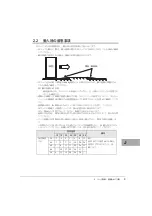
Page 73: ...4 ラック設置後の取り扱いについて 73 J 5 0 5 0 ࡢሙྜ ࢣ ࣈࣝ ࣝࢲ 0 ࢥ ࣛࢵࢺ 0 ࢧࣛࢿࢪ 5 0 5 0 ࡢሙྜ ࢣ ࣈࣝ ࣝࢲ 0 ࢥ ࣛࢵࢺ 0 ࢧࣛࢿࢪ ...

Page 74: ...め込 みます 1U 用の場合 中央の穴 左右合計 2ヶ所 2U 用の場合 2U 目の下方穴 左右合計 2ヶ所 3U 用の場合 2U 目の中央穴 左右合計 2ヶ所 図は 1U 2U 3U 用をまとめて表示していますが 実際の取り付けは空きスペー スに応じて 適切なサイズを選択し 取り付けてください 品 名 型 名 構成品および数量 1U ブランクパネル 19R 26BP1 19RB26BP1 ブランクパネル 1U 用 1 2U ブランクパネル 19R 26BP2 19RB26BP2 ブランクパネル 2U 用 1 3U ブランクパネル 19R 26BP3 19RB26BP3 ブランクパネル 3U 用 1 ࡉ ࡦࠢࡄࡀ 7 ࡉ ࡦࠢࡄࡀ 7 ࡉ ࡦࠢࡄࡀ 7 㧔ขࠅઃߌᓟߩ ᘒ㧕 วࡇࡦ ᣇⓣ ਅᣇⓣ ਛᄩⓣ ...

Page 75: ... 直径約 5mm の場合 90 本程度です 構成品を確認し 必要な工具類を準備します 構成品 下表参照 がすべて揃っていることを確認します また必要な工具類を準備します プラスドライバ 2 番 M5 セルフタッピンネジ用 プラスドライバ 3 番 M6 ネジ用 ケージナット工具 M6 ケージナット用 サイドケーブルダクトの取り付けは 以下の手順で行います 1 ケージナットを取り付ける 2 リヤブラケットを仮止めする 3 サイドケーブルダクト本体を差し込む 4 リヤブラケット サイドケーブルダクト本体 フロントパネルを固定す る 以下にサイドケーブルダクトの取り付け方法を示します 例 ラック左側へ取り付ける場合 サイドケーブルダクトを取り付ける箇所にケーブルホルダーが取り付けてある場合は ケーブルホルダーを取り外します サイドダクトケーブル 型名 19R 27SD1 品名 数量 フロントパネル...

Page 76: ...76 4 9 1 ケージナットの取り付け ケージナットの取り付け方法については 4 1 ケージナット取り付け 取り外し手順 を 参照してください 1 ラック前面側の開口部上下の角穴に M6 ケージナットを取り付けてくださ い 中央の穴 上下 2ヶ所 0 ࢣ ࢪࢼࢵࢺ 0 ࢣ ࢪࢼࢵࢺ ࢫࢣ ࣝ ...

Page 77: ...ケットの仮止め 1 背面側より 後側ラックの柱に5ケ1組で開けてあるネジ穴の一番下に M5 セルフタッピンネジを 5mm 程度ラックの柱と隙間ができるように仮 止めしてください 2 リヤブラケットの下側固定穴を手順1で取り付けた M5 セルフタッピンネ ジに引っ掛けて上側を M5 セルフタッピンネジで固定してください 3 仮止めしていた下側の M5 セルフタッピングネジを本締めして固定してく ださい 0 ࢭࣝࣇࢱࢵࣆࣥࢢࢿࢪ 㸦 㠃ഃ㸧 ࣛࢵࢡࡢᰕ ࣜࣖࣈࣛࢣࢵࢺ ...

Page 78: ...78 4 9 3 サイドケーブルダクト本体の挿入 1 サイドケーブルダクト本体を前面側からリヤブラケットに挿入します サイドケーブルダクト本体はまっすぐに挿入してください 左右方向に振れると リヤブラケットと干渉して挿入できない場合があります リヤブラケットと干渉 した場合は 一度 ケーブルダクト本体を引き出し再度まっすぐにして挿入して ください ๓㠃ഃ ࣜࣖࣈࣛࢣࢵࢺ ࢣ ࣈࣝࢲࢡࢺᮏయ ...

Page 79: ...4 ラック設置後の取り扱いについて 79 J 4 9 4 リヤブラケット サイドケーブルダクト本体 フロン トパネルの固定 1 背面側でサイドケーブルダクト本体とリヤブラケットを添付の M5 セルフ タッピンネジ 2 本で固定します 0 ࢭࣝࣇࢱࢵࣆࣥࢢࢿࢪ 㸦 㠃ഃ㸧 ...

Page 80: ...80 2 前面側よりフロントパネルをサイドケーブルダクト本体にかぶせ M6 ネ ジ 2 本で固定します フロントパネルはゴムがフロントパネルとサイドケーブルダクト本体の間に挟ま るように取り付けてください フロントパネルはサイドケーブルダクトと共締めになります ๓㠃ഃ 0 ࢿࢪ ࣇࣟࣥࢺࣃࢿࣝ ࢧ ࢻࢣ ࣈࣝࢲࢡࢺᮏయ ...

Page 81: ... 必要な工具類を準備します 構成品 下表参照 がすべて揃っていることを確認します また必要な工具類を準備します スパナ M10 ボルト用 以下にスタビライザー L 字型 の取り付け方法を示します 4 10 1 スタビライザー L 字型 の取り付け 1 前面より取り付け用ボルト 4 本を使用してスタビライザー本体をラック へ固定します スタビライザー スリム L 字型 型名 19R 26FS1 スタビライザー スタンダード L 字型 型名 19R 27FS1 品名 数量 スタビライザー本体 1 M10 ボルト 4 ဳࠬ ࡆ ࠗࠩขࠅઃߌࠗࡔ ࠫ ...

Page 82: ...成品を確認し 必要な工具類を準備します 構成品 下表参照 がすべて揃っていることを確認します また必要な工具類を準備します プラスドライバ 2 番 M5 サラネジ用 以下にスタビライザー 引出型 の取り付け方法を示します 4 11 1 スタビライザー 引出型 の取り付け 1 前面よりスタビライザー本体をラックの下へ差し込みます スタビライザー 引出型 型名 19R 26FS2 品名 数量 スタビライザー本体 1 取り付けプレート 1 M5 サラネジ 6 六角レンチ 6mm 1 ࢫࢱࣅࣛ ࢨᮏయ ๓㠃ഃ ...

Page 83: ...4 ラック設置後の取り扱いについて 83 J 2 前面より M5 サラネジでスタビライザー本体をラックに仮固定します 次の手順 3 で背面からスタビライザー本体を固定します スタビライザー本体が落下しない程度に仮固定してください 0 ࢧࣛࢿࢪ ๓㠃ഃ ...

Page 84: ...84 3 背面より M5 サラネジで取り付けプレートとラック およびスタビライ ザー本体を固定します 4 前面の M5 サラネジを本締めします 0 ࢧࣛࢿࢪ ྲྀ ࡅࣉࣞ ࢺ 㠃ഃ ...

Page 85: ...必要な工具類を準備します 構成品 下表参照 がすべて揃っていることを確認します また必要な工具類を準備します スパナ M10 ボルト用 耐震キット スリム 基本 型名 19R 26ST1 耐震キット スタンダード 基本 型名 19R 27ST1 品名 数量 前面パーツ 1 後面パーツ 1 側面パーツ 2 M10 ボルト 16 耐震キット スリム 増設 型名 19R 26ST2 耐震キット スタンダード 増設 型名 19R 27ST2 品名 数量 前面パーツ 1 後面パーツ 1 M10 ボルト 8 ...

Page 86: ...86 4 12 1 耐震キットの取り付け 以下に耐震キットの取り付け方法を示します 1 取り付け用ボルト各 4 本を使用して対象面のパーツをラックへ固定しま す 2 前面と背面のパーツは 2 本のボルトで床に固定します 3 側面のパーツは 3 本のボルトで床に固定します 床固定用の部材はお客様でご用意願います 床固定用穴径は φ20mm 耐震キットの板厚は 4 5mm です 㔡ࠠ ขࠅઃߌࠗࡔ ࠫ ...

Page 87: ...成品 数量 パワーディストリビューションユニット 100V NEMA 5 15Rx8 1U 19R 26P11 コンセントボックス 1 M5 ケージナット 4 M5 ネジ 4 パワーディストリビューションユニット 200V NEMA L6 15Rx8 1U 19R 26P21 コンセントボックス 1 M5 ケージナット 4 M5 ネジ 4 パワーディストリビューションユニット 200V IEC320 C13x4 1U 19R 26P31 コンセントボックス 1 M5 ケージナット 4 M5 ネジ 4 パワーディストリビューションユニット 200V IEC320 C19x3 1U 19R 26P41 コンセントボックス 1 M5 ケージナット 4 M5 ネジ 4 ...

Page 88: ...88 ...

Page 89: ...11 19R 26P21 19R 26P31 19R 26P41 1 後扉を開き コンセントボックスを搭載する位置を確認して ラック背面 の柱それぞれに M5 ケージナットを取り付けます 後扉の開き方については 3 3 後扉の開き方 を ケージナットの取り付け方法に ついては 4 1 ケージナット取り付け 取り外し手順 を参照してください 2 ラック背面より コンセントボックス 19R 26P11 19R 26P21 19R 26P31 19R 26P41 を挿入し M5 ネジ 4ヶ所 で固定します ...

Page 90: ...バーを操作して ON にしてください 注意 コンセントボックスに装置の電源プラグを接続する際は コンセントの奥まで差し 込んでください 奥まで差し込まずに使用すると 故障や火災の原因にとなりま す コンセントボックス 19R 26P31 19R 26P41 にあらかじめ用意されているケー ブルクランプは 電源ケーブルが自然に抜けることを防ぐための電源ケーブル保持 用です また 装置保守時などに 誤って電源ケーブルが抜けてしまわないように 対処が必要な場合は ラックのケーブルホルダーなどに電源ケーブルを固定するな どの対策を施してください コンセントボックスが過電流を検出して サーキットブレーカーが OFF になった場 合 接続されている装置に短絡 ショート などの異常が発生しています このま まサーキットブレーカーを ON にすると 分電盤のブレーカーが切断したり 接続 されている装置に焼...

Page 91: ...ーディストリビューションユニット 100V NEMA 5 15Rx8 0U 19R 27P10 コンセントボックス 1 金具キット 1 コアラット 3 M5 ネジ 3 パワーディストリビューションユニット 200V NEMA L6 15Rx8 0U 19R 27P20 コンセントボックス 1 金具キット 1 コアラット 3 M5 ネジ 3 パワーディストリビューションユニット 200V IEC320 C13x4 0U 19R 27P30 コンセントボックス 1 金具キット 1 コアラット 3 M5 ネジ 3 パワーディストリビューションユニット 200V IEC320 C19x3 0U 19R 27P40 コンセントボックス 1 金具キット 1 コアラット 3 M5 ネジ 3 ...

Page 92: ...92 ...

Page 93: ...R 27P10 19R 27P20 19R 27P30 19R 27P40 コンセントボックス 0U は 19 インチラックモデル 2724 2737 2742 にのみ搭載が可能 です また ラック背面の左右それぞれに 下表の台数が搭載可能です 搭載ラックとコンセントボックス 0U 最大搭載可能台数 ラック片側 19R 27P10 19R 27P20 19R 27P30 19R 27P40 モデル 2724 2 2 2 2 モデル 2737 2 2 2 2 モデル 2742 3 3 3 3 ...

Page 94: ...94 搭載数は サイドケーブルダクトが取り付けされていない場合に限っての台数です コンセントボックス 0U は サイドケーブルダクトと排他取り付けとなります サイドケーブルダクトについては 4 9 サイドケーブルダクトの取り付け手順 を参考に してください ...

Page 95: ...4 ラック設置後の取り扱いについて 95 J 1 コンセントボックス 0U を実装したい箇所にコアラットを取り付けま す コアラットの取り付けは 4 2 コアラットの取り付け 取り外し手順 を参照して ください ...

Page 96: ...96 M5 ネジ 2ヶ所 を外して金具キットから板を取り出し ラックの搭載予定位置にあてが います 鉛筆などでコアラット実装位置をマーキングすると 採寸の代替ができます 2 手順 1 で取り付けたコアラットを利用して 板を M5 ネジで固定します ...

Page 97: ...4 ラック設置後の取り扱いについて 97 J 3 手順 2 で取り付けた板に 下記の金具を沿わせるようにラック柱との間 に挿入して M5 ネジで固定します 4 コンセントボックスを下図のように挿入します 19R 27P10 19R 27P20 は コンセントボックスの左右に実装されている L 字金具を外し て挿入してください ...

Page 98: ...ンセントボックスが前方に出てこないように 添付のコンセントボック ス抑え金具を取り付けます 注 19R 27P30 19R 27P40 用の金具キットは共用ですが コンセントボックス抑 え金具は異なります コンセントボックスを取り付けた後に 1 種類が余ります が 大切に保管してください 6 添付のケーブルクランプをコンセントボックスのアウトレット付近に取り 付けます 19R 27P30 19R 27P40 のみ ...

Page 99: ...ーキットブレーカーを搭載しています コンセントボック スの電源プラグを PDU の入力電源プラグ形状に嵌合するコンセントに接続後は 各サー キットブレーカーのレバーを操作して ON にしてください 注意 コンセントボックスに装置の電源プラグを接続する際は コンセントの奥まで差し 込んでください 奥まで差し込まずに使用すると 故障や火災の原因にとなりま す コンセントボックス 19R 27P30 19R 27P40 にあらかじめ用意されているケー ブルクランプは 電源ケーブルが自然に抜けることを防ぐための電源ケーブル保持 用です また 装置保守時などに 誤って電源ケーブルが抜けてしまわないように 対処が必要な場合は ラックのケーブルホルダーなどに電源ケーブルを固定するな どの対策を施してください コンセントボックスが過電流を検出して サーキットブレーカーが OFF になった場 合 接続されて...

Page 100: ......

Page 101: ...y to death personal injury severe physical damage or other loss hereinafter High Safety Required Use including without limitation nuclear reaction control in nuclear facility aircraft flight control air traffic control mass transport control medical life support system missile launch control in weapon system You shall not use this Product without securing the sufficient safety required for the Hig...

Page 102: ...re copyrights of their respective manufacturers All Rights Reserved Copyright FUJITSU LIMITED 2011 2012 Symbols Meaning These sections explain prohibited actions and points to note when using this product Make sure to read these sections These sections explain information needed to operate the hardware and software properly Make sure to read these sections This mark indicates reference pages or ma...

Page 103: ...t edition An asterisk indicates a section in the previous edition Edition Date Revised section Added Deleted Altered Note Details 01 2011 11 02 2012 01 Whole manual Model 2737 was added 03 2012 08 Updated only Japanese edition 04 2012 12 Section 1 2 Changed Devices that can be mounted on this rack were changed ...

Page 104: ...alling the Rack 120 3 5 Connecting Racks 122 4 Handling the Rack after Installation 128 4 1 Inserting and Removing Cage Nuts 128 4 2 Installing and Removing Core Spring Nuts 132 4 3 Changing the Position of the Door Rotation Axis 134 4 4 Mounting a General purpose Table Fixed Type 151 4 5 Mounting a General purpose Table Movable Type 157 4 6 Mounting the Laptop Storage Rack 163 4 7 Attaching the C...

Page 105: ...724 2737 2742 2616 2624 and 2642 1 1 Specifications The rack specifications are listed below Model 2724 Model 2737 Model 2742 Model 2616 Model 2624 Model 2642 Unit mounting capacity 24 U 37 U 42 U 16 U 24 U 42 U Type name Base rack 19R 272A2 19R 273A2 19R 274A2 19R 261A2 19R 262A2 19R 264A2 Expansion rack 19R 273B2 19R 274B2 19R 264B2 Size W x D x H mm 700 x 1050 x 1200 700 x 1050 x 1800 700 x 105...

Page 106: ...n this rack This rack can accommodate the following types of Fujitsu products PC servers UNIX servers Storage systems Mission Critical IA Servers MC IA Servers Network products For more information consult your Fujitsu sales representative ...

Page 107: ...ay collapse since the maximum load associated with the rack may reach about 1 000 kg Secure a sufficient installation area to ensure normal operation and maintenance of the rack system Do not place metallic objects or containers bearing water such as vases flowerpots or drinking glasses on or near the rack It may lead to failure fire or electric shock Avoid placing the rack in locations exposed to...

Page 108: ...t of the rack rather than the middle of the rack to keep the rack from falling over The barycentric position of the rack can be higher than the center of the rack depending on where individual devices are installed Also do not push on the rack sides Doing so may cause the rack to fall over Pushing against the center of the front door or the air vent opening may cause them to become deformed Move t...

Page 109: ...e Secure the following space 1 The external rack dimensions depend on the specifications of the rack 2 This applies to cases where the upper wiring area is used However it does not apply to 16 U and 24 U racks 1 600mm 700mm 400mm 500mm 1000mm 1050mm 1400mm 1400mm 3400mm 3500mm 1 1400mm 1 600mm 700mm 2 200mm 1 845mm 16U 1200mm 24U 1800mm 37U 2000mm 42U Rack front view Rack top view Front of rack Sp...

Page 110: ...eling feet that are provided on the bottom of the rack Adjust the leveling feet so that the rack is level Keep the casters 1 to 2 mm above the floor Use bolts to secure the rack to the floor slab Failure to use bolts to secure the rack to the floor slab may cause the rack to fall over during any earthquake with an acceleration of more than 2 5 m s2 250 gal If the rack falls over the result may be ...

Page 111: ...device again through the suction surface which may result in device malfunction or a shortened service life of the device Do not remove the front or rear doors of the rack The sheer weight of these doors may result in serious injury if they fall over If the doors need to be removed contact a Fujitsu Limited maintenance engineer Contact a Fujitsu Limited maintenance engineer before attempting to mo...

Page 112: ...handle Item Specifications Product name 19 inch rack Model 2724 base rack Type name 19R 272A2 Appearance Coated black front and rear doors with punched metal finish Unit mounting capacity 24 U Size W x D x H mm 700 x 1050 x 1200 Maximum weight bearing load kg Total rack capacity 571 kg 1 Total load capacity 480 kg excluding rack Rack 91 kg Door opening ratio 80 Accessories Items already attached t...

Page 113: ... name 19R 273A2 19R 273B2 Appearance Coated black front and rear doors with punched metal finish Unit mounting capacity 37 U Size W x D x H mm 700 x 1050 x 1800 Maximum weight bearing load kg Total rack capacity 864kg 1 Total load capacity 740kg excluding rack Rack 124kg Total rack capacity 840kg 1 Total load capacity 740kg excluding rack Rack 100kg Door opening ratio 80 Accessories Items already ...

Page 114: ...4B2 Appearance Coated black front and rear doors with punched metal finish Unit mounting capacity 42 U Size W x D x H mm 700 x 1050 x 2000 Maximum weight bearing load kg Total rack capacity 969kg 1 Total load capacity 840kg excluding rack Rack 129kg Total rack capacity 943kg 1 Total load capacity 840kg excluding rack Rack 103kg Door opening ratio 80 Accessories Items already attached to the rack w...

Page 115: ...ted black front and rear doors with punched metal finish Unit mounting capacity 16 U Size W x D x H mm 600 x 1050 x 845 Maximum weight bearing load kg Total rack capacity 387kg 1 Total load capacity 320kg excluding rack Rack 67kg Door opening ratio 75 Accessories Items already attached to the rack when shipped Front door rear door and a pair of side covers Items in their own packages when shipped ...

Page 116: ...ear doors with punched metal finish Unit mounting capacity 24 U Size W x D x H mm 600 x 1050 x 1200 Maximum weight bearing load kg Total rack capacity 559kg 1 Total load capacity 480kg excluding rack Rack 79kg Door opening ratio 80 Accessories Items already attached to the rack when shipped Front door rear door and a pair of side covers Items in their own packages when shipped with the rack Rack d...

Page 117: ...ame 19R 264A2 19R 264B2 Appearance Coated black front and rear doors with punched metal finish Unit mounting capacity 42 U Size W x D x H mm 600 x 1050 x 2000 Maximum weight bearing load kg Total rack capacity 954kg 1 Total load capacity 840kg excluding rack Rack 114kg Total rack capacity 928kg 1 Total load capacity 840kg excluding rack Rack 88kg Door opening ratio 80 Accessories Items already att...

Page 118: ... 1 Turn the door key to unlock the door Pull the handle Caution Close the front door after fully securing the installed devices Failure to do so may cause the devices to fall off the rack and be damaged in the event of an earthquake ...

Page 119: ...3 Rack Configuration and Installation 119 E 3 3 Opening the Rear Door 1 Turn the door key to unlock the door Pull up the rack handle turn it in the direction of the arrow and pull ...

Page 120: ...0 m s2 1000 gal 2 Method where the rack is not anchored to a stabilizing surface Attach a stabilizer before installation Note The attached stabilizer is a means of preventing the rack from tipping over during device maintenance If the rack is not anchored to a stabilizing surface be sure to attach a stabilizer before installation The stabilizer is an optional product not supplied with this rack St...

Page 121: ...hen secure the rack to the slab building floor using the holes in the kit 2 Securing the rack using the leveling feet Anchor the rack to the slab building floor using the M20 screw holes in the ground plate of the leveling feet and M20 bolts with a length of 17 mm If the rack is not anchored to a stabilizing surface be sure to prepare one of the above stabilizers and attach it to the rack Failure ...

Page 122: ...e power to the server and peripherals and disconnect the power cables from the outlet Otherwise there may be electric shock or failure of the equipment To prevent injury ensure that at least two persons perform the rack connection work Otherwise injury may result You may get on a stepladder when working on the upper part of the rack Be careful not to fall from the stepladder Do not put your foot o...

Page 123: ...g screws for the top cover and then remove the side cover Remove the two M12 screws securing the top cover at the front and rear corners on the right since the other rack will be connected to the right of this rack Remove the 10 screws securing the side cover and then remove the side cover Note Be careful when working at height on the top cover Never put your foot on the rack because it is very da...

Page 124: ...of the existing rack Either one can be attached to the top For information on the locations for attaching them see the detailed figure that shows the locations for attaching the vertical shield rubber jointing strips Attach the horizontal shield rubber jointing strip to the upper D frame on the right side of the existing rack For information on the location for attaching it see the detailed figure...

Page 125: ...H frame of the rack on the side to be connected to the other rack left side when viewed from the front Install M6 core spring nuts at the bottom of the rear H frame of the rack on the side to be connected to the other rack right side when viewed from the rear For information on the procedure for installing the core spring nuts see 4 2 Installing and Removing Core Spring Nuts 6 Align the height of ...

Page 126: ...ld rubber protrudes from the racks or goes inside a rack when the expansion rack is aligned with the existing rack adjust it by pulling it out or pushing it inside with your fingers Using the M6 core spring nuts installed on the front and rear H frames of the racks in steps 3 and 5 secure the lower mounting fixture with M6 flat head screws Fully tighten the M12 hexagon bolts that were temporarily ...

Page 127: ...emoved from the existing rack Note The weight of the side cover is about 13 kg Be careful when mounting it 9 Mount the front and rear doors of the existing and expansion racks Lastly mount the front and rear doors to complete the rack connection procedure For information on the procedure for mounting the front and rear doors see 4 3 Changing the Position of the Door Rotation Axis Side cover Side c...

Page 128: ...nsert one edge of the cage nut into the cage nut hole of the rack The following figure shows the case where the edge of the cage nut is inserted into the lower edge of the hole 2 From the outside of the rack insert the tip of the cage nut tool into the hole that has the installed cage nut and snap the other edge of the cage nut into the hole Cage nut Cage nut tool appearance Cage nut tool Directio...

Page 129: ...the tool or standard screwdriver is completely inserted between the edge of the cage and the mounting flange If the tip is inserted incompletely the edge of the tool or standard screwdriver may slip off leading to potential injury Secure the cage nut such as with adhesive tape to prevent it from falling into the rack When holding the cage nut between your fingertips be sure to grasp its left and r...

Page 130: ...nded or relocated in the future Procedure using a standard screwdriver Caution Be sure not to place any finger anywhere past the points indicated Otherwise the finger may strike the rack when you push on the cage which may lead to injury Secure the cage nut such as with adhesive tape to prevent it from falling into the rack When holding the cage nut between your fingertips be sure to grasp its lef...

Page 131: ...tallation 131 E 1 Insert the tip of a standard screwdriver between the edge of the cage and the mounting flange and then press the edge of the cage 2 Push down on the standard screwdriver to remove the cage nut Standard screwdriver ...

Page 132: ... to rotate with the point of a pen or a small tipped standard screwdriver 2 Confirm that the core spring nut in the groove of the aluminum frame is not tilted Confirm that the screw thread of the core spring nut is visible from outside the groove ࠕ ࡒࡈ ࡓᢿ㕙 Aluminum frame Be careful that core spring nut is not tilted Cross section view of aluminum frame Core spring nut Aluminum frame Core spring nut...

Page 133: ...ion 1 and then rotate it in direction 2 It is easier to rotate with the point of a pen or a small tipped standard screwdriver 2 Pull the core spring nut in direction 3 to remove it It is easier to remove with the point of a pen or a small tipped standard screwdriver ࠕ ࡒࡈ ࡓᢿ㕙 Aluminum frame Core spring nut Cross section view of aluminum frame ...

Page 134: ... will require certain degrees of strength Work carefully The tools required for the following operations include a Phillips screwdriver No 2 and No 3 bits torque driver No 2 bit but not absolute necessary cage nut tool hexagon wrench socket sizes 3 and 4 and box wrench socket size 7 The box wrench is required only for work on the rear door 4 3 1 Changing the position of the rotation axis of the fr...

Page 135: ...ng nuts For Model 2642 Remove the M5 flat head screws to remove the upper and lower lock plates and then remove the M5 core spring nuts For information on the procedure for removing the core spring nuts see 4 2 Installing and Removing Core Spring Nuts Be careful not to lose the parts and screws removed here They will be used later Note Be careful because the bar nut for the hinge may fall out when...

Page 136: ...information on the procedure for installing the core spring nuts see 4 2 Installing and Removing Core Spring Nuts When inserting a bar nut for the hinge in the groove of the aluminum frame rotate it in the groove Align the center of the M6 hexagon socket set screw of the bar nut for the hinge with the punch on the aluminum frame Align the center of each screw hole of the M5 or M6 core spring nuts ...

Page 137: ... and lower parts of the frame For Models 2724 2737 2742 2616 and 2624 Secure them with M6 screws For Model 2642 Secure them with M5 screws Confirm that the shield rubber is attached to the upper and lower lock plates Upper lock The shield rubber should be along the top Lower lock The shield rubber should be along the bottom of the bracket Model 2642 Shield rubber Model 2724 2737 2742 Model 2616 26...

Page 138: ...de and the upper and lower door bars Remove the rail guide from the door bar Remove the upper and lower door bars by rotating the bar in the direction of arrow 1 When removing the rail guide from the door bar bend it as shown at 2 in the figure Door side hinge M5 hexagon socket bolt M4 screw Upper door bar Bending of guide Rail guide Rail guide Lower door bar ...

Page 139: ...screws which are 13 mm and 25 mm long Note The decorative panel is a part separate from the handle body Be careful because it may fall off when the tapping screws are removed Be careful not to lose the parts and screws removed here They will be used later 13 mm long tapping screws 25 mm long tapping screws Decorative panel Handle body Flat washer Rotation control member 13 mm long tapping screws ...

Page 140: ...or each tapping screw location use a tapping screw of the same length as that removed in step 6 Using a tapping screw of a different length may damage the part Note Use a torque driver to tighten the tapping screws to a tightening torque of 1 0 N m If no torque driver is available be careful not to overtighten them Otherwise you may damage the handle 13 mm long tapping screws 13 mm long tapping sc...

Page 141: ...r door bars using M12 screws Push the door side hinge straight into the metal plate of the door Install the upper and lower door bars by rotating the tilted bar to orientation 1 When removing the rail guide from the door bar bend it as shown at 2 in the figure Bending of guide Door side hinge M5 hexagon socket bolt M4 screw Upper door bar Lower door bar Rail guide ࠬࠤ Firmly push top and side of do...

Page 142: ...the door and the rack The front door may be hard to install because the notches for the hinges on the door are bent to control the opening and closing angle Confirm that both the upper and lower door side hinges pins are definitely inserted in the rack side hinges This completes the procedure for changing the position of the rotation axis of the front door Rack side hinge Door side hinge Notch for...

Page 143: ... Remove the M6 screws to remove the upper and lower rack side hinges Remove the M6 hexagon socket set screws to remove the bar nuts for the upper and lower hinges Remove the lock plate located near the center and then remove the core spring nut For Models 2724 2737 2742 2616 and 2624 Remove the M6 screws to remove the lock plate located near the center and then remove the M6 core spring nut For Mo...

Page 144: ... out when the M6 hexagon socket set screw is loosened Model 2724 2737 2742 Model 2616 2624 M6 screw M6 screws Rack side hinge M6 hexagon socket set screw Bar nut for hinge Model 2642 M5 flat head screws Lock plate M5 core spring nuts Lock plate M6 core spring nut ...

Page 145: ... For information on the procedure for installing the core spring nuts see 4 2 Installing and Removing Core Spring Nuts When inserting a bar nut for the hinge in the groove of the aluminum frame rotate it in the groove Align the center of the M6 hexagon socket set screw of the bar nut for the hinge with the punch on the aluminum frame Align the center of each screw hole of the M5 or M6 core spring ...

Page 146: ...s with M6 screws to the H frame Use the core spring nut s to install a lock plate near the center of the frame For Models 2724 2737 2742 2616 and 2624 Secure it with an M6 screw For Model 2642 Secure it with M5 screws Model 2642 Model 2724 2737 2742 Model 2616 2624 Lock plate Lock plate M6 screws Rack side hinge M6 screw M5 screws ...

Page 147: ...or side hinges and the handle hole cover Remove the M5 hexagon socket bolts to remove the door side hinges To remove the handle hole cover remove the M4 hexagon nuts with flange Door side hinge M5 hexagon socket bolt Handle hole cover M4 hexagon nuts with flange ...

Page 148: ...cket Note The grip is a part separate from the handle body Be careful because it may fall off when the tapping screws are removed Be careful not to lose the parts and screws removed here They will be used later Tapping screw M6 hexagon bolt with flange Handle body Lock bracket Rotation control member Resins for fixing handle in position Grip Tapping screw ...

Page 149: ...ges and the handle hole cover Install the door side hinges with the M5 hexagon socket bolts Install the handle hole cover with the M4 hexagon nuts with flange Push the door side hinge straight into the metal plate of the door Changing gear orientation of rotation control member ࠬࠤ Rotate by 90 degrees ࠬࠤ Resins for fixing handle in position Tapping screws Rotation control member Lock bracket M6 he...

Page 150: ...en the door and the rack The rear door may be hard to install because the notches for the hinges on the door are bent to control the opening and closing angle Confirm that both the upper and lower door side hinges pins are definitely inserted in the rack side hinges This completes the procedure for changing the position of the rotation axis of the rear door Rack side hinge Door side hinge Notch fo...

Page 151: ... nuts into the rack posts front and rear For information on the procedure for inserting the cage nuts see 4 1 Inserting and Removing Cage Nuts 1 Open the front door and insert the M6 cage nuts into the front post of the rack The mounting locations are as follows one nut in each of the upper and lower square holes among the three square holes height of 1 U at the location line marking the mounting ...

Page 152: ... of the left and right sides make up a total of four nuts Align the heights of all attached M6 cage nuts 4 4 2 Attaching rear brackets and temporarily mounting the table 1 Using the rear M6 cage nuts that were attached in step 2 according to 4 4 1 Inserting cage nuts temporarily fix rear brackets R and L to the rack post Use M6 screws to fix the brackets in position Mounting location 1 U Front Loc...

Page 153: ...allation directions for rear brackets L and R 2 Temporarily mount the table by inserting the hook at the front of the table into the square hole right above the M6 cage nut that was attached in step 2 according to 4 4 1 Inserting cage nuts Place the rear of the table on the rear brackets L and R that were attached in step 1 M6 screws Rear bracket R Rear bracket L Rack post M6 cage nut M6 cage nut ...

Page 154: ... nuts by applying M6 screws Start work after confirming that rear brackets L and R will not fall down when the table is placed on them When mounting the table provisionally ensure that the table is securely mounted with the front hook fully inserted in the relevant square hole Also ensure that the rear part of the table is securely mounted on rear brackets L and R Do not stop supporting the table ...

Page 155: ... against rear brackets L and R adequately do so after slightly loosening the M6 screws marked with an asterisk 3 Fully tighten the M6 screws to secure rear brackets L and R which were temporarily fixed in position in step 1 according to 4 4 2 Attaching rear brackets and temporarily mounting the table to the rack posts Same locations as in rear bracket L Cross section G G Screw holes in rear bracke...

Page 156: ...ts have been tightened Confirm that the table does not occupy the U space under the table 5 Make readjustments as required by loosening the M6 screws that secure the table to the rack posts U space after mounting Must not be below location line ...

Page 157: ...are the necessary tools Phillips screwdrivers No 3 bits Cage nut tool The procedure for mounting a general purpose table movable type is as follows 1 Insert cage nuts 2 Attach rear brackets 3 Mount the table General purpose table movable type Type name 19R 26TR2 Component name Quantity Table 1 Rear bracket L 1 Rear bracket R 1 M6 cage nut 8 M5 cage nut 2 M6 screw 12 Belt 2 Installation Guide 1 ...

Page 158: ...e holes among the three square holes height of 1 U at the location line marking the mounting location of the table Two nuts on each of the left and right sides make up a total of four nuts 2 Open the rear door and insert the M6 cage nuts into the rear post of the rack The mounting locations on rack posts are as follows one nut in each of the upper and lower square holes among the three square hole...

Page 159: ...the extent that the table will not drop down when it is placed on the rear brackets 2 Confirm that front brackets L and R being held in position by the simple retainer mechanism of the slide rails do not move Front brackets L and R are part of the table 3 Insert the hooks at the front of front brackets L and R into the square holes right above the M6 cage nuts that were attached in step 2 accordin...

Page 160: ...uch a way that the table rear does not face downward Start work after confirming that front brackets L and R are held by the table with the simple retainer mechanism of the slide rails and do not move The slide rails and front brackets L and R are assembled with the table before shipment Start work after confirming that rear brackets L and R will not fall down when the table is placed on them When...

Page 161: ... front bracket R so that no gaps appear in the directions of arrows B and C If you are unable to press against rear brackets L and R adequately do so after slightly loosening the M6 screws marked with an asterisk The table can be drawn out about 152 mm until the screw holes for securing rear brackets L and R are visible Do not draw it out too much see section G G 4 Put away the table that was draw...

Page 162: ...hat all M6 screws have been tightened Tighten the panel fastener to secure the table in position Confirm that the table does not occupy the U space under the table 7 Make readjustments as required by loosening the M6 screws that secure the table to the rack posts Rack post Rear bracket R M6 screws Rear bracket R Rear bracket L Panel fastener Table U space after mounting Must not be below location ...

Page 163: ...ed see the table below Also prepare the necessary tools Phillips screwdrivers No 2 bit Cage nut tool supplied with the rack Laptop storage rack table type Type name 19R 26TR3 Product name Quantity Table unit 1 Cable arm 1 Rail unit 2 M5 cage nut 10 Accessory M5 screw 9 Accessory Hook and loop fastener belt 1m Accessory Installation Guide 1 Accessory ...

Page 164: ...ion line marking the mounting location of the table Three nuts on each of the left and right sides make up a total of six nuts 2 Insert M5 cage nuts into the rear rack posts The mounting locations on the rear of the rack are as follows one nut in each of the upper and lower square holes among the three square holes at the location line Two nuts on each of the left and right sides make up a total o...

Page 165: ...ts of the rack Then using the supplied M5 screws secure them to the M5 cage nuts that were inserted in step 1 and 2 into the rack posts front and rear according to 4 6 1 Inserting cage nuts Eight screws Loosen the two adjusting screws on the rear brackets to adjust the units to the appropriate pitch between the rack posts front and rear on which they are mounted After the adjustment fully tighten ...

Page 166: ...inserting the unit for the first time the movement may feel stiff Gradually insert the table unit while moving it back and forth several times 2 Push the left and right disconnect springs on the slide rails simultaneously to further insert the table unit Rear bracket Adjusting screws Front bracket Table unit Rail unit Rail unit Push in this direction Disconnect spring ...

Page 167: ...n the panel fastener on the front of the table unit to secure the unit in position This completes the mounting work Caution For transport shipment of the rack with the table mounted we recommend placing cush ioning material reused packing material in gaps to prevent the cable arm from knocking against the rack Cable arm Rail unit M5 screw Panel fastener Tape Cushioning material Cable arm ...

Page 168: ...rocedure for attaching the cable holder is as follows Install the core spring nut on the rack frame and secure the cable holder The procedure for attaching the cable holder is shown below Model Type name Front Rear 2724 2737 2742 19R 27CM1 19RB27CM1 19R 27CM2 19RB27CM2 2616 2624 19R 26CM1 19RB26CM1 19R 26CM2 19RB26CM2 2642 19R 26CM11 19RB26CM11 19R 26CM21 19RB26CM21 Component and quantity Cable ho...

Page 169: ...ching the cable holder For information on the procedure for installing the core spring nuts see 4 2 Installing and Removing Core Spring Nuts The core spring nut will be installed on the front or rear frame of the rack Front Rear ࠬࠤ Front frame ࠬࠤ Rear frame ...

Page 170: ...he front or rear frame of the rack and secure the cable holder with the M5 flat head screw M5 core spring nut Cable holder M5 flat head screw For 19R 27CM1 19RB27CM1 For 19R 27CM2 19RB27CM2 M5 core spring nut Cable holder M5 flat head screw ...

Page 171: ...4 Handling the Rack after Installation 171 E For 19R 26CM1 19RB26CM1 M5 core spring nut Cable holder M5 flat head screw For 19R 26CM2 19RB26CM2 M5 core spring nut Cable holder M5 flat head screw ...

Page 172: ...172 For 19R 26CM11 19RB26CM11 M5 core spring nut Cable holder M5 flat head screw For 19R 26CM21 19RB26CM21 M5 core spring nut Cable holder M5 flat head screw ...

Page 173: ... and right at 1 U 2 U Two lower holes on the left and right at 2 U 3 U Two center holes on the left and right at 2 U The figure shows a general representation of 1 U 2 U and 3 U blank panels In actual work select and mount the appropriate size of blank panel according to the available space Component name Type name Component and quantity 1 U blank panel 19R 26BP1 19RB26BP1 1 U blank panel x 1 2 U ...

Page 174: ...d prepare the necessary tools Confirm that all components have been delivered see the table below Also prepare the necessary tools Phillips screwdriver No 2 bit For M5 self tapping screws Phillips screwdriver No 3 bit For M6 screws Cage nut tool For M6 cage nuts The procedure for attaching the side cable duct is as follows 1 Insert cage nuts 2 Temporarily secure the rear bracket 3 Insert the side ...

Page 175: ... For information on the procedure for inserting the cage nuts see 4 1 Inserting and Removing Cage Nuts 1 Insert M6 cage nuts in the square holes at the top and bottom of the opening in the front of the rack Two center holes at the top and bottom M6 cage nut M6 cage nut ࠬࠤ ...

Page 176: ...tighten it leaving a clearance of about 5 mm between the screw and the rack post 2 Fit the lower securing hole of the rear bracket to the M5 self tapping screw installed in step 1 and secure the upper part with an M5 self tapping screw 3 Fully tighten the lower M5 self tapping screw which was temporarily tightened to secure the bracket M5 self tapping screws Rear Rack post Rear bracket ...

Page 177: ...body from the front into the rear bracket Be sure to insert the side cable duct body straight in If it is moved slightly to the right or left during insertion it may hit the rear bracket edge preventing its insertion If it hits the rear bracket edge pull it out once and reinsert it Front Rear bracket Cable duct body ...

Page 178: ...Securing the rear bracket the side cable duct body and the front panel 1 From the rear secure the side cable duct body and the rear bracket with the two supplied M5 self tapping screws M5 self tapping screws Rear ...

Page 179: ... the side cable duct body and secure it with two M6 screws Install the front panel such that the rubber cones are between the front panel and the side cable duct body The front panel and the side cable duct are held firmly together by the screws Front M6 screws Front panel Cable duct body ...

Page 180: ...lso prepare the necessary tools Spanner For M10 bolts The procedure for attaching the stabilizer L shaped is shown below 4 10 1 Attaching the stabilizer L shaped 1 From the front secure the stabilizer body to the rack with four bolts Stabilizer slim L shaped Type name 19R 26FS1 Stabilizer standard L shaped Type name 19R 27FS1 Product name Quantity YStabilizer body 1 M10 bolt 4 Illustration of atta...

Page 181: ...ivered see the table below Also prepare the necessary tools Phillips screwdriver No 2 bit For M5 flat head screws The procedure for attaching the stabilizer pullout type is shown below 4 11 1 Attaching the stabilizer pullout type 1 From the front insert the stabilizer body under the rack Stabilizer pullout type Type name 19R 26FS2 Product name Quantity Stabilizer bodyf 1 Mounting plate 1 M5 flat h...

Page 182: ...re the stabilizer body to the rack with M5 flat head screws The stabilizer body will be secured from the rear in the next step step 3 Temporarily secure the stabilizer body to the extent that it will not fall off M5 flat head screws Front ...

Page 183: ...k after Installation 183 E 3 From the rear secure the mounting plate the rack and the stabilizer body with M5 flat head screws 4 Fully tighten the M5 flat head screws on the front M5 flat head screws Mounting plate Rear ...

Page 184: ...tools Spanner For M10 bolts Quake Proof Stabilizer kit slim base Type name 19R 26ST1 Quake Proof Stabilizer kit standard base Type name 19R 27ST1 Product name Quantity Front part 1 Rear part 1 Side part 2 M10 bolt 16 Quake Proof Stabilizer kit slim expansion Type name 19R 26ST2 Quake Proof Stabilizer kit standard expansion Type name 19R 27ST2 Product name Quantity Front part 1 Rear part 1 M10 bolt...

Page 185: ...ack using four mounting bolts per part 2 Anchor the front part and rear part to the floor each with two bolts 3 Anchor the side parts to the floor each with three bolts Customers are requested to provide their own components for floor anchoring The floor anchoring hole has a diameter of 20 mm and the board of the Quake Proof Stabilizer kit has a thickness of 4 5 mm Illustration of the attached Qua...

Page 186: ......

Page 187: ...y resulting from the use of the data contained in this manual All rights reserved We will replace your copy of this manual if any pages are missing or collated incorrectly 19 インチラック モデル 2724 2737 2742 2616 2624 2642 取扱説明書 19 inch Rack Model 2724 2737 2742 2616 2624 2642 User s Guide 19R 272A2 19R 273A2 19R 273B2 19R 274A2 19R 274B2 19R 261A2 19R 262A2 19R 264A2 19R 264B2 C120 E665 04XA 発 行 日 発行責任 ...

Page 188: ......

Reviews: