27" & 30" WARMER DRAWER INSTALLATION INSTRUCTIONS
INSTALLATION AND SERVICE MUST BE PERFORMED BY A QUALIFIED INSTALLER.
IMPORTANT: SAVE FOR LOCAL ELECTRICAL INSPECTOR'S USE.
READ AND SAVE THESE INSTRUCTIONS FOR FUTURE REFERENCE.
FOR YOUR SAFETY: Do not store or use gasoline or other flammable vapors and liquids in the
vicinity of this or any other appliance.
GENERAL INFORMATION
The Warmer Drawer can be used: As a stand alone appliance or as a combination Warmer Drawer with a built-in oven
mounted above
IMPORTANT:
The warmer drawer must be installed on a surface leveled from left to right, rear to front and the surface
must be capable of supporting 100 pounds (45 Kg).
P/N 318201807 (0606) Rev. B
English – pages 1-4
Español – páginas 5-8
Français – pages 9-12
D
A
B
F
E
C
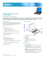
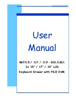
Warmer Drawer Dimensions
NOTE:
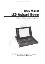
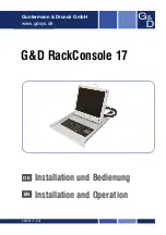
A 60" (152 cm) long cable is supplied with the
Warmer Drawer.
Stand Alone Installation
FLOOR
Warmer Drawer
Cutout
Warmer Drawer
60" (152 cm)
Cord
Minimum distance to floor
41/2" (11,4 cm)
* Note
: It is also possible to install this warmer drawer in a
height opening of 9¼" (23.5 cm). Please refer to page 3
for complete instructions.
Printed in United States
A. HEIGHT
B. WIDTH
C. DEPTH
27" Models
10" (25,4 cm)
27" (68,6 cm)
23 3/8" (59.4 cm)
30" Models
10" (25,4 cm)
30" (76,2 cm)
23 3/8" (59.4 cm)
D. CUTOUT
E. CUTOUT
F. CUTOUT G. HEIGHT
HEIGHT
WIDTH
DEPTH
27" - Min. 8 3/8" (21,3 cm)
25½ " (64,8 cm) 23 5/8" (60 cm) 1½" (3.8 cm)
Max. 8 5/8" (21,9 cm)
25¾ " (65,4 cm)
24" (61 cm)
30" -Min. 8 3/8" (21,3 cm)
28½ " (72,4 cm) 23 5/8" (60 cm) 1½" (3.8 cm)
Max. 8 5/8" (21,9 cm)
28¾" (73 cm)
24" (61 cm)
Depends on critical
dimension H
Depends on critical
dimension H
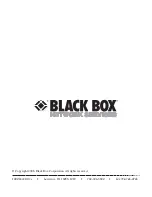
D. CUTOUT
E. CUTOUT
F. CUTOUT
HEIGHT
WIDTH
DEPTH
27" Models- Min. 8 3/8" (21,3 cm)
25 1/2 " (64,8 cm)
23 5/8" (60 cm)
Max. 8 5/8" (21,9 cm)* 25 3/4 " (65,4 cm)
24" (61 cm)
30" Models- Min. 8 3/8" (21,3 cm)
28 1/2 " (72,4 cm)
23 5/8" (60 cm)
Max. 8 5/8" (21,9 cm)*
28 3/4" (73 cm)
24" (61 cm)
A. HEIGHT
B. WIDTH
C. DEPTH
27" Models
10" (25,4 cm)
27" (68,6 cm)
23 3/8" (59.4 cm)
30" Models
10" (25,4 cm)
30" (76,2 cm)
23 3/8" (59.4 cm)
D
G
H*
F
E
J**
J**
A
B
C
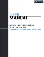
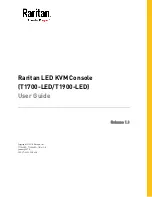
IMPORTANT:
The Warmer Drawer runs off a single
phase three-wire 120 volt, 60 hertz, AC only electrical
supply with ground.
H*
=10-1/8" (25.7 cm) Min.
is a Critical
dimension and must be applied
.
Bottom of oven cutout
Caution
: Two 3" (7,6 cm) wide X 3/
4" (1,9 cm) thick planks have to be
installed and they should be able to
support 200 pounds. (90,7 Kg)
29½"
(74.9 cm)
Combination Warmer Drawer/
30" (76 cm) Built-in Oven Installation
J**
= 3" (7.6cm) Max.
Electrical Junction Box for wall oven can be
lower than warmer drawer cutout or higher than walloven cutout.