background image

Publication #5995666392 

October 2015

Technical Service Manual

Laundry Center 

Summary of Contents for FFLE3911QW

Page 1: ...Publication 5995666392 October 2015 Technical Service Manual Laundry Center ...

Page 2: ...I ...

Page 3: ...7 2 WASHING CYCLE SELECTION 56 7 3 WASHING CYCLE SETTINGS 57 7 4 DRYING PROCEDURES 59 7 5 DRYING CYCLE SELECTION 61 8 ELECTRICAL CHARACTERISTICS FFLE3911QW AND FFLG4033QW 8 1 ELECTRONIC CONTROL 64 8 1 1 Electronic Control Board Dryer 64 8 1 2 Main Control Board Washer 66 8 1 3 User Interface UI Board Washer 67 8 1 4 Motor Control Board Washer 70 8 2 SCHEMATIC DIAGRAM FOR LAUNDRY CENTER DRYER ELECT...

Page 4: ...TY 107 11 6 COMPONENTS ACCESSIBILITY FROM FRONT PANEL 108 11 6 1 Motor Blower Accessibility 108 11 6 2 Drum Accessibility 109 11 6 3 Exhaust Thermistor Accessibility 111 11 6 4 Thermostat Safety Accessibility 111 11 6 5 Inlet Thermal Limiter Accessibility 111 11 6 6 Outlet Thermal Limiter Accessibility 112 11 7 HEATER ELECTRIC ASSEMBLY ACCESSIBILITY 112 11 8 HEATER GAS ASSEMBLY ACCESSIBILITY 113 1...

Page 5: ...ULT 165 E32 ELECTRONIC PRESSURE SENSOR CALIBRATION PROBLEMS 166 E35 WATER OVERLOAD 168 E41 DOOR LID OPENED 170 E42 DOOR LID LOCK FAILURE 171 E43 DOOR LID LOCK TRIAC FAILURE 172 E44 DOOR LID CLOSED SENSING FAILURE 173 E45 DOOR LID TRIAC SENSING FAILURE 174 E55 MOTOR UNDER SPEED FAILURE 175 E58 MOTOR OVER CURRENT 177 E59 MOTOR NOT FOLLOWING 179 E5A MOTOR CONTROL OVER HEATING 181 E5H MOTOR CONTROL UN...

Page 6: ...that requires special attention from the user CAUTION Used with the safety alert symbol indicates a hazardous situation which if not avoided could result in minor or moderate injury Read the entire manual before attempting to Install Assemble or Operate this product Pay attention to all Warnings Cautions and Notes Failure to do so could result in serious personal injury and or equipment damage DEF...

Page 7: ...rol System This manual is intended to use for service engineers of Electrolux The manual includes Product Features Specifications Exploded Views and Bills of Materials BOM Installation Operating Instructions Electrical Characteristics and Specifications Accessibility to the Electrical Components Settings Diagnostics Error alarm codes Troubleshooting based on alarm codes 1 Purpose of this Manual ...

Page 8: ...llecting drips of water Always empty the appliance before laying it on its side for any servicing The resistance values of the components shown in this Service Manual SM are purely indicative and approximate Replace the heating element with one that has the same characteristics to maintain safety measures for the appliance Ensure gas pipelines are connected properly as mentioned in the installatio...

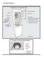
Page 9: ...8 3 Product Features ...

Page 10: ...Difference Description FFLE FFLG3911QW FFLE FFLG4033QW Heater Assembly Electric Gas Electric Gas Moisture Bar No Softener Valve 2 Valve 3 Valve Bleach Softener Dispenser Bleach Dispenser Bleach Softner Dispenser Energy Saver Option No ...

Page 11: ...mperature Control Yes Water Level Adjustments Yes Yes Bleach Dispenser Yes Yes Fabric Softener Dispenser Yes Agitate Speeds Strokes Min Variable Variable Spin Speeds RPM 600 600 Sound Package Silent Design Wash Cycles Wash Cycles Specialty Cycles 8 0 9 0 Washer Options Temperature Selections 3 Rotary 3 Rotary Water Levels 3 Automatic Energy Saver Option Yes Dryer Features Total Capacity D O E Cu F...

Page 12: ...sion Kit PN PCK3100 Drying Rack PN DRLC PN DRLC Certifications ENERGY STAR Yes Specifications Maximum Exhaust Duct Length1 Ft 56 56 Gas Connection Rear Power Supply Connection Location Middle Rear Middle Rear Water Inlet Connection Location Middle Rear Middle Rear Voltage Rating 240V 60Hz 30A 120V 60Hz 15A Connected Load kW Rating 240 Volts 5 1 1 03 Amps 240 Volts 22 13 120 Volts2 Heating Element ...

Page 13: ...b at www frigidaire com for detailed installation instructions 1 Rigid metal duct preferred semi rigid optional and allow deductions for elbows and vents Refer to Installation Guide on the web at www frigidaire com for additional information 2 For use on adequately wired 120 V dedicated circuit having 2 wire service with a separate ground wire Appliance must be grounded for safe operation ...

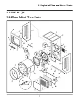
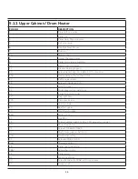
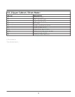
Page 14: ...13 5 1 FFLE3911QW 5 1 1 Upper Cabinet Drum Heater 5 Exploded View and List of Parts ...

Page 15: ...fle heater shield 18 Screw 10 16AB x 0 375 20 Glide flat dryer 21 Drum dryer svc kit galv steel 22 Panel Front weld white 22 Plug light hole 22A Pin panel locator 23 Seal felt lower 24 Seal felt upper 25 Door Catch upper 26 Switch door 27 Lint Trap 29 Screw quadrex head 10 14 x 1 00 vane mtg special 30 Vane straight low 31 Screw 10 16AB x 0 625 32 Shaft drum support ball hitch 33 Thermostat safety...

Page 16: ...ner door white 48 Panel outer door white 49 Door Strike 50 Insulator heat shield outer door 51 Insulator heater housing 52 Terminal Block heater housing 54 Wiring Harness door switch w o light 62 Screw 10 16AB x 0 500 80 Screw pan head 8 18B x 0 31 Functional parts Non Illustrated parts ...

Page 17: ...16 5 1 2 Motor Blower Belt ...

Page 18: ...9 Pan Upper L C dryer formed 22 Spring idler 23 Idler Arm Assy with pulley 23 Terminal Block main 25 Belt dryer LC 26 Block support 27 Clamp motor mtg 28 Motor dryer drive with pulley 33 Shield access 38 Elbow 90 Deg 4 Fixed 39 Screw 8 pan head 10 10B x 0 500 cr sq drive 41 Bracket support side 42 Bracket marriage dryer 44 Bracket L mounting cabinet rear external 48 Pan bottom LC dryer 50 Cover su...

Page 19: ...18 5 1 3 Control Panel ...

Page 20: ...cation with housing 15 Switch PTS cycle select 8 position 18 Console decorated white 21 Knob Cycle Selector 22 Screw 8 pan head 10 10B x 0 500 cr sq drive 23 Wiring Harness main LC 23 Terminal Block main 29 Wiring Harness LC Dryer electrical 32 Cable Tie 5 60 inch plastic 39 Switch Option 3 pos 80 Screw Phillips 6 19 x 0 650 Functional parts Non Illustrated parts ...

Page 21: ...20 5 2 FFLG4033QW 5 2 1 Upper Cabinet Drum Heater ...

Page 22: ...re sensor assembly 19A Clip end cap mtg U type 20 Glide flat dryer 21 Drum LC GALV GD 22 Panel Front weld asmy LC Dr 22 Plug light hole 22A Pin panel locator 23 Seal felt lower 24 Seal felt upper 25 Door Catch upper 26 Switch door 27 Lint Trap 29 Screw quadrex head 10 14 x 1 00 vane mtg special 30 Vane straight 31 Screw 10 16AB x 0 625 32 Shaft drum support ball hitch 33 Thermostat safety 35 Screw...

Page 23: ...7 Panel inner door white 48 Panel outer door white 49 Door Strike 50 Insulator heat shield outer door 52 Terminal block heater housing 54 Harness Door SW w sensor 62 Screw 10 16AB x 0 500 80 Screw pan head 8 18B x 0 31 Functional parts Non Illustrated parts ...

Page 24: ...23 5 2 2 Motor Blower Belt ...

Page 25: ...with pulley 25 Belt poly V 26 Block support 27 Clamp motor mtg 28 Motor dryer drive with pulley 31 Power Cord electric svce 33 Shield access area cover 34 Screw hex washer head 10 32 x 0 375 ground 38 Elbow exhaust duct 39 Screw 8 pan head 10 10B x 0 500 cr sq drive 41 Bracket support side 42 Bracket marriage dryer 44 Bracket L mounting cabinet rear external 48 Pan bottom LC dryer 50 Cover support...

Page 26: ... 76 Collar alignment gas valve 77 Burner gas 79 Sensor radiant 80 Screw pan head 8 18B x 0 31 80A Tube burner 85 Shield heat 86 Plate adapter 87 Cable Tie push mount 5 20 inch LP Conversion Kit natural to LP Functional parts Non Illustrated parts ...

Page 27: ...26 5 2 3 Control Panel ...

Page 28: ... 13 Switch on off white round 15 Switch PTS cycle select 9 pos 18 Console decorated control panel 21 Knob Cycle Selector 22 Screw 8 pan head 10 10B x 0 500 cr sq drive 23 Wiring Harness main 29 Harness main LC D gas 32 Cable Tie 5 60 inch plastic 39 Switch rotary 2 pos 40 Switch rotary 5 pos 41 Switch rotary 4 pos 80 Screw Phillips 6 19 x 0 650 Functional parts Non Illustrated parts ...

Page 29: ...3QW 5 3 1 Motor Gear Box Assembly Tub 5 3 1 Motor Gear Box Assembly Tub POS NO DESCRIPTION 1 Motor Gear Box Assembly 2 Screw 10 PLCS 3 Screw 2 PLCS 4 Motor Brake Actuator Clutch 5 Drain Pump Assembly 6 Screw 3 PLCS Functional parts ...

Page 30: ...29 5 3 2 Control Board Washer 5 3 2 Control Board Washer POS NO DESCRIPTION 1 Motor Access Panel 2 Screw 2 PLCS 3 Screw 2 PLCS 4 Main Board Assy UN Main Board Assy PRO Functional parts ...

Page 31: ...sher Cabinet Assembly 2 Cushion Pads 2 PLCS 3 Suspension Rods Assembly 4 PLCS 4 Pivots 4 PLCS 5 Cushion Pads Felt Only 2 PLCS 6 LPA CAP 7 Screw 8 Agitator Assembly 9 Screw 8 PLCS 10 Spin Tub Assembly 11 Hub Assembly 12 Splash Tub Assembly 13 Suspension Assembly 4 PLCS ...

Page 32: ...31 5 3 3 Wash Assembly POS NO DESCRIPTION 14 Screw 2 PLCS 15 Lock Hub Functional parts ...

Page 33: ...32 5 3 4 Cabinet Assembly ...

Page 34: ...Assembly 9 Structural Bracket LH 10 Screw 4 PLCS 11 3 Coil water valve Model FFLG4033QW 11A 2 Coil water valve Model FFLE3911QW 12 Low Frequency Analog Pressure Sensor 13 Top Panel and Lid Assembly 14 Lid Lock 15 Fastener 16 Screw 17 UIMC Assembly 18 Bracket UIMC 19 Cover UIMC 20 Softener Dispenser Assembly Model FFLG4033QW 20A Bleach Dispenser Model FFLE3911QW Functional parts ...

Page 35: ... accordance with the National Fuel Gas Code ANSI Z223 1 NFPA 54 The dryer is designed under ANSI Z 21 5 1 or ANSI UL 2158 CAN CSA C22 2 No 112 latest editions for HOME USE only This dryer is not recommended for commercial applications such as restaurants beauty salons and others Do not install a clothes dryer with flexible plastic or flexible foil venting material Flexible venting material are kno...

Page 36: ...Installation section 3 Wire Power Supply Cord KIT not supplied 3 wire receptacle NEMA type 10 30R The dryer MUST employ a 3 conductor power supply cord NEMA 10 30 type SRDT rated at 240 volt AC minimum 30 amp with 3 open end spade lug connectors with upturned ends or closed loop connectors and marked for use with clothes dryers For 3 wire cord connection instructions see ELECTRICAL CONNECTIONS FOR...

Page 37: ... system during any pressure testing of the gas supply piping system at test pressures in excess of 1 2 psig 3 45 kPa 7 Isolate the dryer from the gas supply piping system during any pressure testing of the gas supply piping system at test pressures equal to or less than 1 2 psig 3 45 kPa 8 Connections for the gas supply MUST comply with the Standard for Connectors for Gas Appliances ANSI Z21 24 6 ...

Page 38: ...r drain hose have a qualified technician install a longer drain hose according to your model number available from an authorized parts distributor For drain systems in the floor install a syphon break kit available from your local hardware store ...

Page 39: ...erials Flexible venting materials are known to collapse get easily crushed and trap lint These conditions will obstruct air flow in the clothes dryer and increase the risk of fire WARNING FIRE HAZARD A clothes dryer must be exhausted outdoors Do not exhaust dryer into a chimney a wall a ceiling an attic a crawl space or any concealed space of a building A clothes dryer produces combustible lint If...

Page 40: ...aust system is acceptable certain extenuating circumstances could affect the performance of the dryer 1 Use the rigid metal duct work only 2 Venting vertically through a roof may expose the exhaust system to down drafts causing an increase in vent restriction WARNING FIRE HAZARD Exceeding the length of duct pipe or number of elbows as seen in MAXIMUM LENGTH charts can cause an accumulation of lint...

Page 41: ... can be installed directly through the outside wall To exhaust to the side or down add an 8 inches 20 3 cm length of standard 4 inches 102 mm diameter duct and a 90 elbow Refer to Clearance Requirements for more information 6 3 Manufactured or Mobile Home Installation 1 Installation MUST conform to current Manufactured Home Construction and Safety Standard Title 24 CFR Part 32 80 formerly the Fede...

Page 42: ...op and bottom of the door is required Openings should be located 3 inches 7 6 cm from the bottom and top of door Openings are required to be unobstructed when a door is installed A louvered door with equivalent air openings throughout is acceptable WARNING DO NOT INSTALL YOUR LAUNDRY CENTER Do not set your Laundry Center under the following circumstances In an area exposed to dripping water or out...

Page 43: ...n hose length beyond clamp approximately 52 inches 132 cm WARNING EXPLOSION HAZARD Do not install the dryer where gasoline or other flammables are kept or stored If the dryer is installed in a garage it must be a minimum of 18 inches 45 7 cm above the floor Failure to do so can result in death explosion fire or burns ...

Page 44: ...ppliance MUST be properly grounded Electrical shock can occur if the dryer is not properly grounded Follow the instructions in this manual for proper grounding Do not use an extension cord with this dryer Some extension cords are not designed to withstand the amount of electrical current this dryer utilizes and can melt creating electrical shock and or fire hazard Locate the dryer within reach of ...

Page 45: ...er USA and Canada 1 The Laundry Center is equipped with a 3 prong grounding plug for your protection against shock hazard and should be plugged directly into a properly grounded 3 prong receptacle 2 The plug must be inserted into an appropriate outlet that is properly installed and grounded in accordance with all local codes and ordinances If in doubt call a licensed electrician 3 DO NOT modify th...

Page 46: ...rical Connection non Canada 4 wire cord 4 wire receptacle NEMA type 14 30R 1 Turn OFF the power supply to outlet 2 Remove the screw securing the terminal block access cover in the lower corner on the back of the dryer 3 Install a UL approved strain relief according to the power cord strain relief manufacturer s instructions in the power cord entry hole below the access panel At this time the strai...

Page 47: ...ng the Laundry Center on the ground 1 With the Laundry Center within 4 feet 1 m of its final location place a level on top of the washer lid 2 Use adjustable pliers to adjust the leveling of legs so that the Laundry Center is levelled front to rear and side to side and stable corner to corner 3 Press down on alternate corners and sides and feel for the slightest movement Adjust the appropriate leg...

Page 48: ...2 3 turns with pliers Do not bend kink or pinch water inlet hoses 4 Turn ON the water and check for leakages Connecting Vents 1 Remove the two screws items A to the right securing the front access panel of the dryer to the dryer cabinet Lift the panel until the tabs can be disengaged from the cabinet remove the panel and set aside 2 Connect the exhaust duct to the outside exhaust system Use a 4 in...

Page 49: ...er It contains valuable and helpful information that will save you time and money 5 Run the washer through a complete cycle checking for water leakages and proper operation 6 If you have any questions during initial operation review the Avoid Service Checklist in your Use and Care Guide before calling for service 7 Place these instructions in a location near the appliance for future reference NOTE...

Page 50: ... N 137019200 A Universal Appliance Wrench is available to aid in dryer washer feet adjustment Touch Up Paint Pens White Touch Up Pen P N 5304468812 Other colors may be available Contact the source from where you purchased your Laundry Center Replacement Parts If replacements parts are needed for your Laundry Center contact the source where you purchased your laundry center or refer to your Use and...

Page 51: ... installation 6 6 Gas Connection 1 Remove the shipping cap from the gas pipe at the rear of the dryer 2 Connect a 1 2 inch 1 27 cm I D semi rigid or approved pipe from the gas supply line to the 3 8 inch 0 96 cm pipe located on the back of the dryer Use a 1 2 inch to 3 8 inch 1 27 cm to 0 96 cm reducer for the connection Apply an approved thread sealer that is resistant to the corrosive action of ...

Page 52: ...er pressure MUST be between 10 psi 0 69 bars and 120 psi 8 27 bars The pressure difference between hot and cold water cannot be more than 10 psi The water department can advise you of the water pressure 6 8 Drain System Requirements 1 Drain capable of eliminating 17 gals 64 3 L per minute 2 A standpipe diameter of 1 1 4 inches 3 18 cm minimum 3 The height of the standpipe above the floor should IM...

Page 53: ...tallations requiring a longer drain hose get a qualified technician to install a longer drain hose according to your model number available from an authorized parts distributor For drain systems in the floor install a syphon break kit available from your local hardware store ...

Page 54: ...of fiberglass left in the drum may transfer to fabrics in other loads and cause skin irritation and or damage to fabrics 2 Prepare Items for Washing a Empty pockets b Brush off lint and dirt Shake out rugs and beach towels c Close zippers fasten hooks button up buttons and tie strings sashes Remove non washable trims and ornaments d Mend rips and tears to prevent further damage during washing e Tu...

Page 55: ...e lid b Refer to the bleach manufacturer s directions for quantity to add c Then add 1 cup 240 ml of water to flush the dispenser d Do not use powdered bleach in the bleach dispenser Add powdered bleach to the empty tub 6 Add laundry load to washer a For best washing performance dry load level should not be higher than the upper row of holes in the wash tub Do not overload the washer b Combine lar...

Page 56: ...ons on following pages 9 Start the Washer a Close the washer lid The washer will not operate with the lid open b Push in or turn the cycle selector knob or turn any option knob to wake the washer You will hear three beeps to indicate that the washer is ready to operate c After making your selections push in the selector knob to start the cycle You will hear one beep and the washer lid will lock d ...

Page 57: ...s wrinkling color transfer or odors may develop in items left in the washer after the cycle has ended 7 2 Washing Cycle Selection FFLE3911QW FFLG4033QW This manual covers many models and not all cycles options or features listed are available on every model Consoles shown are for reference only Your model may differ Turn the cycle selector in either direction to the cycle required To change the cy...

Page 58: ...elect models only For example quickly wash a small lightly soiled load in 25 minutes Quick Wash on select models only Quickly wash a small lightly soiled load in 25 minutes Rinse and Spin Select rinse spin for loads that need a cold water rinse or to add fabric softener that may have been omitted in a regular cycle Presoak Use this cycle to soak heavily soiled and stained items before washing Any ...

Page 59: ...on select models only If your model is equipped with an automatic fabric softener dispenser turn ON the fabric softener switch for correct operation See Care and Cleaning section for dispenser cleaning procedures Energy Saver on select models only The energy saver option reduces water temperature to save energy lowers water usage slightly and also extracts more water to reduce drying time Safe Sta...

Page 60: ...e items that shed lint from those that attract lint c Check for stains that may not have been removed in washing Repeat stain removal process and wash again before drying The heat from the dryer may set some stains permanently d Place delicate or small items in a mesh bag e Be sure buckles buttons and trim are heatproof and would not damage the drum finish Close zippers button up buttons and faste...

Page 61: ...each load See the section Dryer Operating Instructions for more information 5 Start the Dryer a Close the dryer door The dryer will not operate with the door open b Push in or turn the cycle selector knob or turn any option knob to wake the dryer You will hear three beeps to indicate that the dryer is ready to operate c After making your selections push in the selector knob to start the cycle You ...

Page 62: ...of the load as it tumbles through the heated air With Auto Dry cycles the load will automatically be dried at the selected temperature to a specific dryness level Auto Dry cycles save time and energy and protect fabrics When the load has reached the dryness level it will continue to tumble during a cool down period This helps to reduce wrinkling and makes items easier to handle during unloading Th...

Page 63: ...age following a trip It provides approximately 10 minutes of tumbling followed by a 5 minute cool down period Timed Dry To manually select the drying time for any load turn the knob to a numbered setting 15 on select models 30 60 or 90 minutes Moisture sensing bars if equipped are not active and the dryer will continue to heat throughout the cycle until the final cool down period Drying Cycle Sett...

Page 64: ...Leave space between items but do not let items hang over the sides or through the grids Do not tumble other items when using the drying rack 4 Select a timed cycle If items to be dried contain plastic foam rubber rubber like materials feathers or down then only use the air dry temperature setting 5 When items are dry remove the rack and replace the lint screen If the lint screen is not in place tu...

Page 65: ...y the User Interface UI Board by turning the Program and Dryness Level selector are sent to the Electronic Control Board which powers all the electrical components Thermistors Thermal limiters High limit thermostat Heater Assembly Door switch and so on It controls the temperature of inlet and exhaust air through the Thermistor sensor It senses and controls the opening closing and locking condition...

Page 66: ...oard FFLE3911QW and FFLG4033QW Dryer NOTE The Dryer Electronic Control Board controls all the functions of dryer whereas the Washer User Interface and the Motor Control Board is accommodated separately for specific functions ...

Page 67: ...ard Washer and all other electrical components The commands acquired by the User Interface UI Board by turning the selector and so on are sent to the Main Control Board which powers all the electrical components Lid Lock Solenoid Valve Pressure sensor Drain Pump Negative Thermal Co efficient NTC Motor Brake Clutch and so on ...

Page 68: ...g temperature to select the required program and to activate ON OFF Fabric softener if required It also accommodates Energy Saver option for model FFLG4033QW It is possible to select the programmes by turning the Selector Knob The buzzer where featured is powered by the User Interface Board User Interface of Laundry Center FFLE3911QW ...

Page 69: ...68 User Interface of Laundry Center FFLG4033QW ...

Page 70: ...69 User Interface User Interface UI Board FFLE3911QW Washer User Interface UI Board FFLG4033QW Washer ...

Page 71: ...from the Main Control Board and sends voltage to the drive motor to spin the drive motor in the proper direction and speed If the motor control is not working properly the drive motor might not spin at all or might spin at the wrong speed Motor Brake Clutch functions is controlled by the Main control Board and the Motor Control Board is powered by the Main Control Board Motor Control Board FFLE391...

Page 72: ...71 8 2 Schematic Diagram for Laundry Center Dryer Electronic Control Board FFLE3911QW and FFLG4033QW ...

Page 73: ...72 8 3 Schematic Diagram for Laundry Center Washer Main Control Board FFLE3911QW and FFLG4033QW ...

Page 74: ...73 8 4 Schematic Diagram for Laundry Center Washer User Interface UI FFLE3911QW and FFLG4033QW ...

Page 75: ...74 8 5 Schematic Diagram for Laundry Center Washer Motor Control Board FFLE3911QW and FFLG4033QW ...

Page 76: ...75 8 6 Wiring Diagram FFLE3911QW Electric Dryer Model ...

Page 77: ...76 8 7 Wiring Diagram FFLG4033QW Gas Dryer Model ...

Page 78: ...77 8 8 Wiring Diagram FFLE3911QW and FFLG4033QW Washer Model ...

Page 79: ...nly PERFORMANCE SPECIFICATIONS Voltage cycles 115V 60Hz 4 8 AMPS Breakdown torque ft oz 24 4 nom Locked rotor current amps 47 max Full load torque ft oz 12 2 nom Full load current amps 4 6 nom Full load watts 340 nom Full load rpm 1685 nom Horse power 1 4 hp output Locked rotor trip time 3 6 sec INSULATION CLASS F 4 Heating Element For Electrical Dryer Model only Wattage 4500W 3 Voltage 240V Resis...

Page 80: ... 6 Outlet Thermal Limiter U L Rated 240V 10A F L A and 60A L R A at 350ºF C S A Rated 120V 15A Resistive Opening Temp 222ºF 8ºF Closing Temp 31ºF 7 Igniter For Gas Dryer Model only Steady State Current to be 2 1 to 3 4 AMPS AT 80 1 VAC and 75º 10ºF Igniter must not exceed 2800 ºF in 10 seconds at 132 1 VAC 75ºF 10ºF Ambient ...

Page 81: ...or 7 GPM MIN 3 Dispenser Solenoid valve 3 coil For Model FFLG4033QW 1375 Ω 10 Resistance at 25 ºC 120 V 60 Hz 6 5 Watts 4 Dispenser Solenoid valve 2 coil For Model FFLE3911QW 1375 Ω 10 Resistance at 25 ºC 120 V 60 Hz 6 5 Watts 5 3 Phase Synchronous Motor M1 M2 6 to 8 Ω M2 M3 6 to 8 Ω M1 M3 6 to 8 Ω 150 V 180 V 54 2 83 3 Hz 2 76 1 96 A 385 420 W 650 1000 RPM 6 Motor Brake Clutch 2900 to 3100 Ω Resi...

Page 82: ...metal chamber Electrical current flowing through the coil creates heat and the air being pulled through the chamber absorbs this heat and becomes hot For Gas Models Gas models are equipped with gas valve and burner assemblies Gas flowing through the valves are burned with the help of an igniter that creates heatand the air being pulled through the chamber absorbs this heat and becomes hot WARNING ...

Page 83: ...82 Specifications S NO Component Specifications 1 Heater Electrical Model Wattage 4500W 3 Resistance Across The Terminals 11Ω 10 Wiring Diagram Gas Dryer FFLG4033QW ...

Page 84: ...rature The thermistor measures the temperature of the air in the dryer and adjusts the heat accordingly When a thermistor fails it can cause the dryer not to heat at all or heat up to the wrong temperature Outlet Thermistor is used to check the temperature of air at exahust WARNING When replacing the Outlet Control Thermistor refer to the code shown in the list of spare parts relating to the appli...

Page 85: ...84 S NO Component Specifications 1 Outlet Control Thermistor Resistance 50KΩ 5 at 25ºC Resistance 12 4KΩ 2 at 60ºC Operating Temp 40 C to 105 C Wiring Diagram FFLG4033QW Specifications ...

Page 86: ...he Dryer Door Switch also senses the position of the door open or closed thus allowing the dryer to start its function only when the door is closed Wiring Diagram FFLE9311QW Door Switch and Drum Light Wiring Diagram FFLG4033QW Door Switch and Drum Light S NO Component Specifications 1 Door Switch Contact Rating to Meet 10A 1 3HP 125 250 VAC 2 Drum Light Voltage 3 5VDC Current 350Ma NOTE The Drum L...

Page 87: ...n the fields and the current induced in the rotor bars generates opposing torque The Motor Assembly is used to drive the Dryer Drum and the Blower The motor is activated from the Electronic Control Board through the Door Switch The motor is equipped with Overload Thermal Protection Tripper This ensures that the motor is switched OFF if any thermal overload occurs 9 5 Single Phase Induction Motor F...

Page 88: ...or current amps 47 max Full load torque ft oz 12 2 nom Full load current amps 4 6 nom Full load watts 340 nom Full load rpm 1685 nom Horse power 1 4 hp output Locked rotor trip time 3 6 sec INSULATION CLASS F Specifications FFLE3911QW and FFLG4033QW Dryer Wiring Diagram FFLE3911QW Wiring Diagram FFLG4033QW ...

Page 89: ...lowing the timer to advance or by stopping it Moisture Sensor Control counts the number of times this short circuit occurs over a given period and act upon that information appropriately More hits would mean more wet clothing in the dryer In such cases the control may delay in advancing the timer for a longer period to allow more time for them to dry Less hits would mean fewer or less damp clothin...

Page 90: ... A Rated 125 250 VAC 25 A Resistive 125 VAC 20 F L A 60 L R A Inductive 240 VAC 10 F L A 60 L R A Inductive Opening Temp 275º 10 8ºF Closing Temp 31ºF Specifications 9 8 Outlet Thermal Limiter FFLE3911QW 9 8 1 General Characteristics It is a heat sensitive fuse attached to the rear panel and it disconnects electrical power to the heater when the dryer gets overheated The specific purpose of the Th...

Page 91: ...90 Wiring Diagram FFLE3911QW Wiring Diagram FFLG4033QW ...

Page 92: ...Limit Thermostat is closed allowing current to flow to the heater without interruption Under normal conditions the dryer s primary operating thermostat will cycle the heater to switch ON and OFF to prevent the temperature from rising too high within the dryer The Hi Limit thermostat will remain unaffected through all these cycles because the temperature inside the dryer will remain lower than what...

Page 93: ...body is stuck in the wheel the rotor can perform small movements clockwise and anticlockwise until the foreign body is released WARNING When replacing the Pump refer to the code shown on the list of spare parts related to the appliance IMPORTANT Synchronous pumps when powered on empty disconnected from the water circuit may not start in some cases because their very construction makes them need an...

Page 94: ... FFLG4033QW S NO Component Specifications 1 Drain Pump 12 to 17 Ω Resistance at 25 ºC 120 V AC 60 Hz 1 4 A 80W Discharge Rate Under Variable Head At 3 FT height from floor 12 GPM MIN At 8 FT height from floor 7 GPM MIN Specifications ...

Page 95: ...Tub and the Pressure sensor When the tub is filled with water it creates a pressure inside the hydraulic circuit that causes the membrane to change position This in turn modifies the position of the core inside the coil thus changing the inductance and the frequency of the oscillating circuit The Main Control Board recognizes how much water has been filled into the tub according to the frequency O...

Page 96: ...for UL application Pressure working range 0 600 mm of H2O Specifications Presssure Frequency Diagram At Water Level 0 mm empty tub Frequency will be 45 4 Hz Mm H20 Hz Points with 100 control of frequency output on assembly line Pressure mm H2O Nominal frequency Hz Water Level at 0 45 400 150 43 140 200 42 350 350 39 990 500 37 772 600 36 560 ...

Page 97: ...loses the door and selects the program the Lid Switch sends the signal to the Lid Lock to lock the Door Thereby the user cannot open the Door while the program is running Wiring Diagram FFLE3911QW and FFLG4033QW S NO Component Specifications 1 Lid Lock Internal contacts 120 240 VAC 50 60 Hz Electrical Life 15000 cycles 3A External Micro switch 16A 250V Power 1 HP 125 VAC 2 HP 250 VAC and Resiatanc...

Page 98: ... magnetic field which rotates in time with the oscillations of the line current The rotor with permanent magnets or electromagnets turns in step with the stator field at the same rate and as a result the rotor provides the second synchronized rotating magnet field of any AC motor It is possible to get an idea of the efficiency of the motor by measuring the resistance of the coils 6 to 8 ohm contac...

Page 99: ...Mechanical jamming of the Solenoid Valve The Solenoid Valve may jam or open without being actuated which will cause flooding if the Pressure Sensor controlling the water level does not trip If this occurs the electronic control system which continuously monitors the flow sensor will lock the door start the Drain Pump and display an ALARM simultaneously 9 14 4 Low Water Pressure The Flow Sensor may...

Page 100: ...99 Wiring Diagram FFLE3911QW and FFLG4033QW S NO Component Specifications 1 Dispenser Solenoid Valve 1375 Ω 10 Resistance at 25 ºC 120 V 60 Hz 6 5 Watts Specifications ...

Page 101: ...r with the agitator and during the spin it disengages the motor with the agitator and engages it with the drum Incase of a door lock failure and when the user opens the door while the program is running the MBC applies the brake to stop the rotation of motor Wiring Diagram FFLE3911QW and FFLG4033QW S NO Component Specifications 1 Motor Brake Clutch MBC 2900 Ω to 3100 Ω Resistance at 25 ºC AC 120 V...

Page 102: ...ough the igniter The igniter is lighted by using a battery powered spark generator that burns the gas and produces heat This heat is used to dry the clothes inside the dryer 10 4 Radiant Flame Sensor 10 4 1 General Characteristics Flame sensor is a device that detects the presence of a flame due to combustion It detects the flame by detecting electromagnetic radiation ionization or heat When the d...

Page 103: ... 1 Loosen the screws 2 See Fig 1 that fixes with left and right panel of the dryer to remove the access panel Step 2 Loosen the Control Panel screws 2 that fixes with the left and right panel of the dryer Step 3 Hold the Control Panel at the bottom and pull See Fig 2 it out Then detach the connectors See Fig 3 to removethe control panel ...

Page 104: ...ontrol Panel console to separate the Electronic Control Board Assembly from the console 11 1 2 Program Selector Accessibility Step 1 Remove the Program Selector knob from the console as shown in Figs 1a and 1b Step 2 Detach the connector from Cycle Selector Switch See Fig 2 and unfasten the 2 snaps to remove the switch from the console See Fig 3 11 1 3 Temperature Selector Accessibility Step 1 Rem...

Page 105: ...ibility FFLG4033QW Gas Dryer Step 1 Loosen the screws 2 See Fig 1 that fixes with the left and right panel of the dryer to remove the access panel Step 2 Loosen the Control Panel screws 2 that fixes with the left and right panel of the dryer Step 3 Hold the Control Panel at the bottom and pull See Fig 2 it out Then detach the connectors See Fig 3 to separate the Control Panel ...

Page 106: ...ch is fitted with the Control Panel console to separate the Electronic Control Board Assembly from the console 11 2 2 Program Selector Accessibility Step 1 Remove the Program Selector knob from the console as shown in Figs 1a and 1b Step 2 Detach the connector from the Cycle Selector Switch See Fig 2 and unfasten the 2 snaps to remove the switch from the console See Fig 3 11 2 3 Temperature Select...

Page 107: ...2 4 Chime Selector Accessibility Step 1 Remove the Chime knob from the console as shown in Figs 1a and 1b Step 2 Detach the connector from the Chime Switch See Fig 2 and unfasten the 2 snaps to remove the switch from the console See Fig 3 11 3 Front Panel Assembly Accessibility Step 1 Loosen the screws 4 of the Front panel Door Assembly as shown in Fig 1 ...

Page 108: ...See Fig 1 from the Electronic Control Board to remove the Front Panel Assembly and then detach the terminals See Fig 2 of the Door switch Step 2 Press the snaps See Fig 3 and pull it out from the front side of the panel assembly to remove the Door Switch 11 5 Moisture Sensor Accessibility Step 1 Loosen the Moisture sensor screws 2 that fits with the Back side of the Front Panel Assembly Drum insid...

Page 109: ...l Limiter 5 Outlet Thermal Limiter 11 6 1 Motor Blower Accessibility Step 1 Loosen the screws 2 which are fixed to the Dryer Back Panel Motor Access Panel and take out the Motor Access Panel Step 2 Push the Idler Arm Assembly See Fig 1 against the spring force and loosen the belt from the motor pulley Figs 2a and 2b Then remove the belt from the front side of the machine as shown in Fig 3 ...

Page 110: ... the base panel of the dryer Step 5 Remove the Idler Arm Assembly from the Motor Cradle Motor support Figs 4a and 4b by unlocking from the pivot hinge Step 6 Detach the connector of the motor See Fig 5 and the earth terminal from the Motor Cradle See Fig 6 Step 7 Loosen the screw that connects the Blower with the exhaust duct Step 8 Pull out the Blower and the Motor Assembly from the Front Side of...

Page 111: ...tep 11 Detach the Blower wheel snaps to separate the Blower wheel from the Motor shaft Step 12 Loosen the screws 2 to remove the Motor and Cradle Assembly from the Blower rear housing Step 13 Remove the Motor clamps 2 with the help of the Plier from the Cradle projection as shown in Figures 6 and 7 NOTE To separate the motor from the Blower Assembly follow these steps ...

Page 112: ...ter Accessibility Detach the Inlet Thermal Limiter terminals See Fig 1 and loosen the screws 2 See Fig 2 that is fixed with the Heating Element Assembly NOTE 1 To access the Exhaust Thermistor access the Front Panel Assembly and the Drum 2 Refer to the Front Panel Accessibility and Drum Accessibility sections for accessing the Drum and Front Panel Assembly NOTE 1 To access the Thermostat Safety ac...

Page 113: ...has to be accessed 2 Refer to the Front Panel Accessibility and Drum Accessibility sections for accessing the Drum and Front Panel Assembly NOTE 1 To access the Outlet Thermal Limiter access the Front Panel Assembly and the Drum 2 Refer to the Front Panel Accessibility and Drum Accessibility sections for accessing the Drum and Front Panel Assembly NOTE Ball Hitch and Dryer Drum support are fixed w...

Page 114: ...1 8 Heater Gas Assembly Accessibility Step 1 Loosen the LCD Support Cover screws 6 which is fixed to the left Panel 2 screws right Panel 2 screws and Access area shield cover 2 screws NOTE 1 To access the Heater Assembly access the Front Panel Assembly and the Drum 2 Refer to the Front Panel Accessibility and the Drum Accessibility sections for accessing the Drum and Front Panel Assembly NOTE Befo...

Page 115: ...crews 2 which are fixed with the Access area shield cover Step 5 Detach the connector See Fig 5 and pull out the Heater Assembly Then detach the Radiant Sensor terminals 2 See Fig 6 while taking the Gas Assembly outside 11 8 1 Radiant Flame Sensor Accessibility Remove the screw See Fig 1 of the Radiant Sensor that fits with the Burner Tube Also remove the clamp See Fig 2 and then detach the termin...

Page 116: ...ed with the Burner Tube Step 2 Remove the wire clip 1 and loosen the screw 2 from the Adapter plate to separate the igniter NOTE The Igniter material is soft and brittle Handle it with care 11 8 3 Gas Valve Assembly Accessibility Loosen the Gas Valve Bracket screws 3 to separate the Gas Valve Assembly ...

Page 117: ... Wait for 5 8 seconds and then reconnect the power cord OR switch ON the Cold Power 5 Within 15 seconds of the power reset or power Up with the Dryness Level Selector if mounted at the High position turn the Cycle Selector to the Casual cycle and the Temperature Selector to the left most highest temperature available position and press and release the Cycle Selector knob There will be a short beep...

Page 118: ...es C NTC short 0 25s On 0 25s Off 0 25s On 3s Off Repeats 255 Times 2 Temp Selector Medium Normal Rocker Switches select models ON Motor Heater Check the Motor and Heater function LEDs On Drying and Cool Down On NOTE If the Diagnostic Mode cannot be entered even after the correct execution of Steps 1 4 check the wiring and the edge connectors i e J7 LC Main Board J7A FSD UI Board J8 LC Main Board ...

Page 119: ... Pattern 5 1s On 1s Off 1s On 1s Off 1s On 1s Off 1s On 3s Off Repeats 255 Times Same LED Pattern 4 N A Error code display Check error codes The repeating sequence will time out automatically after 255 times To refresh the counter change the cycle selector to a different position while still in Diagnostic Mode and come back to the initially selected position 7 Follow the instructions below to exit...

Page 120: ...Stopped in the middle of a cycle 126 6 E54 Centrifugal Switch 2 Heater Thermal Limiter 2 Wiring 127 7 E55 Motor Sensing failure on Main Board Heater Thermal Limiter 2 Wiring 128 8 E56 Belt 128 9 E61 Heater Relay Failure 129 10 E62 Heating Timeout 130 11 E65 High Limit Thermostat trip count too high 131 NOTE 1 1E followed by the numbers mean that it is the first error code recorded Similarly 2E fol...

Page 121: ... Main Board 131 13 E71 NTC Failure 132 14 E72 NTC Failure 133 15 E81 Program Selector Encoder 134 16 E82 Key Stuck 134 17 E93 Software Configuration 135 18 E94 Software Configuration 135 19 E97 Software Configuration 135 20 EA1 Line Frequency 136 21 EA2 High_Line 136 22 EA3 Low_Line 137 23 EA5 Line Amplitude Sensing failure on Main Board 137 ...

Page 122: ...he connectors are correctly inserted Check for any foreign object interfering with Contact Sensor YES Remove the foreign object and repeat the Diagnostic Cycle to check for any further alarms N O Check all the Contact Sensor wiring terminals are connected properly Connector J3 NO Connect it properly and repeat the Diagnostic Cycle to check for any further alarms Replace the Electronic Control Boar...

Page 123: ...ing Remove the obstacle and repeat the Diagnostic Cycle to check for any further alarms Check the Door Switch wiring terminals are connected properly NO Make the connections proper and repeat the Diagnostic Cycle to check for any further alarms Check the continuity between terminals of Door Switch in closed condition Continuity is there Change the Door Switch and repeat the Diagnostic Cycle to che...

Page 124: ...tach the connectors and measure between the terminals 5 4 3 of motor and the earth contact See Figures 2 and 3 Is Resistance value not 0 NO Replace the Motor and repeat the Diagnostic Cycle to check for any further alarms Replace the Motor and repeat the Diagnostic Cycle to check for any further alarms Check Inlet Thermal Limiter for the continuity NO Replace Inlet Thermal Limiter repeat the Diagn...

Page 125: ...124 ...

Page 126: ...the appliance body See Fig 1 Is Resistance value not 0 NO Replace the Electronic Control Board and repeat the Diagnostic Cycle to check for any further alarms Replace the Motor and repeat the Diagnostic Cycle to check for any further alarms Check if wiring between Electronic Control Board and Motor is properly connected NO Replace the wiring and repeat the Diagnostic Cycle to check for any further...

Page 127: ...ings See Fig 2 Replace the defective component After clearing any obstacles wait till the motor is cool because thermal protector may take 30 minutes to reset thermal protector may be tripped because of motor overheating Repeat the Diagnostic Cycle to check for any further alarms Detach the connector from the motor and measure the resistance between terminals 5 4 Check Resistance value are in betw...

Page 128: ...ween 2 6 Ω to 3 2 Ω See Fig 1 NO Replace the motor and repeat the Diagnostic Cycle to check for any further alarms Replace the Heater and repeat the Diagnostic Cycle to check for any further alarms Measure the resistance between the terminals of Heating Element and check whether it is between 11 Ω 10 at room temperature 20 25 C See Fig 3 NO Replace the Heater and repeat the Diagnostic Cycle to che...

Page 129: ...ors are correctly inserted Replace the Electronic Control Board and repeat the Diagnostic Cycle to check for any further alarms E56 E56 Belt Fault E56 Belt Broke and Loose Belt WARNING Check that all the connectors are correctly inserted Check the belt Replace the belt if found broken or loose and repeat the Diagnostic Cycle to check for any further alarms ...

Page 130: ...nic control board See Fig 1 Is Resistance value not 0 NO Replace the Control board and repeat the Diagnostic Cycle to check for any further alarms Replace the heating element and repeat the Diagnostic Cycle to check for any further alarms Check Replace the wiring and repeat the Diagnostic Cycle to check for any further alarms Detach the connectors and measure between the heating element and the ea...

Page 131: ... between the terminals of heating coil is 11 Ω 10 See Fig 2 NO Replace the Heater and repeat the Diagnostic Cycle to check for any further alarms Check Thermal limiter 2 Inlet Thermal Limiter for continuity Continuity is there Replace the Thermal Limiter 2 and repeat the Diagnostic Cycle to check for any further alarms NO Y E S Replace the Electronic Control board and check for any further alarms ...

Page 132: ...rther alarms Check whether the Exhaust vent system is proper there should not be any air blockage See Fig 2 Remove the air blockage and make the exhaust vent system proper and repeat the Diagnostic Cycle to check for any further alarms NO Y E S Replace Repair the High Limit Thermostat and repeat the Diagnostic Cycle to check for any further alarms Y E S Check whether the ventilation of the dryer i...

Page 133: ...urther alarms Measure the value of the Exhaust Thermistor between terminals of J4 wiring connector Is the value correct Between 47 KΩ 66 KΩ at 20 to 25 C See Fig 1 NO Detach the connector and measure directly on the Exhaust Thermistor Is the value correct Between 47 KΩ 66 KΩ at 20 to 25 C See Fig 2 Y E S NO Replace the Thermistor and repeat the Diagnostic Cycle to check for any further alarms Chec...

Page 134: ... further alarms Measure the value of the Thermistor between terminals of J4 wiring connector Is the value correct Between 47 KΩ 66 KΩ at 20 to 25 C See Fig 1 NO Detach the connector and measure directly on the Thermistor Is the value correct Between 47 KΩ 66 KΩ at 20 to 25 C See Fig 2 Y E S NO Replace the Thermistor and repeat the Diagnostic Cycle to check for any further alarms Check Replace the ...

Page 135: ...s and repeat the Diagnostic Cycle to check for any further alarms Does the same Error Code still appear YES E82 E82 Key stuck E82 Key Stuck error wiring cycle selector switch main board and software defect WARNING Check that all the connectors are correctly inserted Remove the selector and knob and restart the dryer Does the problem exist NO Replace the selector and knob and check for any further ...

Page 136: ... error E94 Microprocessor corrupted WARNING Check that all the connectors are correctly inserted Replace the Electronic Control Board and repeat the Diagnostic Cycle to check for any further alarms E97 E97 Software Configuration E97 Wrong MCF data loaded cycle selector switch failure WARNING Check that all the connectors are correctly inserted Replace Cycle Selector Switch and retry if the problem...

Page 137: ...and the Diagnostics Mode cannot be accessed The complete alarm can only be read when the situation has normalized EA1 EA1 Main supply Frequency out of Range EA1 Power supply frequency out of configured range 46 54Hz for 50Hz system and 56 64Hz for 60Hz system WARNING Check that all the connectors are correctly inserted Is the supply line disturbed or the main voltage out of range Replace the Elect...

Page 138: ... system of the home checked repaired by the proper Body Y E S EA3 EA3 Voltage too Low EA3 Line voltage too Low or Electronic Control Board fault WARNING Check that all the connectors are correctly inserted Is the supply line disturbed or the main voltage out of range V 180Vrms for 240V system V 90Vrms for 120V system Replace the Electronic Control Board and repeat the Diagnostic Cycle to check for...

Page 139: ... screws 2 that fixes with the left and right panel of the Laundry Center Dryer Step 3 Hold the Control Panel at the bottom and pull it out Figs 2 and 3 then detach the connector See Fig 4 to remove the Control Panel 14 1 1 User Interface UI Board Accessibility Step 1 Loosen the Screws 3 from the Control Panel console See Fig 1 and then detach the connectors Figs 2a and 2b to separate the Washer Us...

Page 140: ...tor Switch See Fig 2 and then unfasten the snaps 2 to remove the switch from the console See Fig 3 14 1 3 Temperature Selector Accessibility Step 1 Remove the Temperature Selector knob from the console as shown in Fig 1 Step 2 Detach the connector from the Temperature Selector Switch See Fig 2 and unfasten the snaps 2 to remove the switch from the console See Fig 3 ...

Page 141: ...ig 1 Step 2 Detach the connector from the Softener switch See Fig 2 and then unfasten the snaps 2 to remove the switch from the console See Fig 3 14 1 5 Energy Saver Switch Accessibility Step 1 Detach the Energy Saver Switch terminals Step 2 Press the snaps and pull out the switch from the Control Panel console ...

Page 142: ...y Bracket See Fig 1 Step 2 Release the clip that fits in the pocket of the Top Panel See Fig 1 and then lift the Front Panel to remove the panel from the machine See Fig 2 14 3 Motor Control Board Accessibility Step 1 Loosen the screws 2 that fits with the Bracket of the Left Panel as shown in Fig 1 ...

Page 143: ...afely on the floor as shown in Fig 1 so that the bottom of the machine is completely visible Then loosen the Screws 3 that are fitted with the Washer Tub See Fig 2 Step 2 Remove the Drain Hose Clamp See Fig 3 and pull out the drain hose See Fig 4 then detach the connector See Fig 5 and take it out NOTE There is a possibility of water leakage while servicing the drain pump and drain hose Therefore ...

Page 144: ...otor Brake Clutch 14 6 Motor Gear Box Assembly Accessibility Step 1 Lean down the machine safely on the floor as shown in Fig 1 so that the bottom of the machine is completely visible Then remove all the wire clips which are fixed to the Motor Gear Box Assembly See Fig 1 Step 2 Detach the Earth Terminal by loosening the screw which is fitted to the leg Dome and Bracket Assembly See Fig 2 Step 3 Pr...

Page 145: ... key as shown in Fig 5 to disengage the Motor Gear Box Shaft from the Drum Hub Assembly Step 6 Loosen the Motor Gear Box Assembly screws See Fig 6 from the Drum and pull it out as shown in Fig 7 14 7 Main Control Board Accessibility Step 1 Loosen the Main Control Board cover screws 2 which are fitted with the Laundry Center Dryer Rear Panel See Fig 1 and take it out as shown in Fig 2 ...

Page 146: ...en detach the Connectors from the Main Control Board Assembly as shown in Figs 6a and 6b to separate the Motor Control Board Assembly 14 8 Lid Top Panel Assembly Accessibility Step 1 Remove the Softener and the Bleach Dispenser Cover as shown in Fig 1 Step 2 Loosen the Softener and the Bleach Dispenser Screw See Fig 2 which is fitted to the Top Panel then push the dispenser See Fig 3 to take it ou...

Page 147: ...ly remove the Softener and the Bleach Dispenser Assembly 14 8 1 Lid Lock Accessibility Press the snap of the lock and slide it up Now press it from the Top Panel Assembly and pull it out through the other side as shown in Fig 1d NOTE To access Lid lock and remove the Top Panel Assembly Refer to the Top Panel Accessibility section ...

Page 148: ...ews and two service professionals are required to remove in the dryer unit Step 1 Below figure shows top view of washer unit after dryer unit is removed Step 2 Detach the Pressure Sensor snap that fits with the Rear Panel of the washer unit Figs 1a and1b and detach the connector Fig 2 then remove the pressure tube at the switch end See Fig 3 ...

Page 149: ... the Tub hook See Fig 2 which has been attached to the Motor Tub for easy accessibility of the Solenoid Valve Step 2 Detach the hot cold and Secondary Coil connectors and valve outlet to the Tub Connector from the Solenoid Valve Remove the two Solenoid Valve outlet hose clips 1 2 and pull out the hoses Dispenser Hose and Tub Fill Hose to separate the Solenoid Valve See Fig 3 ...

Page 150: ...f times as the second digit of the error code 0 5 seconds ON 0 5 seconds OFF 4 The buzzer stays silent until the Start Pause Cancel buttons are pressed momentarily to read the next error code 15 2 Diagnostic Mode Use this mode under the following conditions In a factory assembly line to perform a manual test of the machine functionality final assembly test By service personell to check for faults ...

Page 151: ...ltaneously 6 Turn the Cycle Selector knob 5 clicks clockwise from the Normal position The drum will stop and the drain pump will activate draining out any water in the tub After draining the clutch actuator will start moving continuously for about 1 minute 7 Turn the Cycle Selector knob 6 clicks clockwise from Normal position The Drain Pump turns on until no water is detected on the sensor the clu...

Page 152: ...rking conditions Door locked water level lower then 140mm for a maximum period of 5 minutes The clutch moves to the agitate position if it is in spin 15 8 Cold Water Valve Test Selector position Turn 2 clicks clockwise from the top Purpose of the test Water loading from the cold water valve Activated components Door lock and cold water valve Clutch Actuator UI behaviour None Working conditions Doo...

Page 153: ...ditions Door locked drum stop run clutch to spin mode and drain until empty 10 seconds more Run clutch actuator for about 100 seconds 15 12 Drain and Spin Test Selector position Turn 6 clicks clockwise from the top Purpose of the test Verify drain system and Pressure Sensor calibration procedure Activated components Door lock main motor drain pump UI behaviour None Working conditions Door locked e...

Page 154: ...Water draining takes too long timed during each drain Drain pipe blocked Drain pump defective or rotor locked Pressure switch defective or blocked Drain pump not energized wiring or main board Cycle Paused after 2 attempts START ON OFF RESET 163 4 E31 Pressure sensor fault Frequency of electronic pressure sensor out of limits Pressure sensor Wiring or main board Cycle abort RESET 165 5 E32 Electro...

Page 155: ...t Safety drain RESET 174 12 E55 Motor under speed Failure During spin the motor speed is lower than the target for 2 minutes Foam or drum weight overload Drum mechanical drag Motor Drain pump Cycle abort ON OFF RESET 175 13 E58 Motor over current High current on motor phase 4 5A Foam or drum weight overload Motor Wiring or Motor Control Board Cycle abort ON OFF RESET 177 14 E59 Motor not following...

Page 156: ...ard Fault Motor Control Board control board is continuously in reset Wiring Motor control board Main board Cycle ends ON OFF RESET 185 21 E71 Washing NTC failure Wrong input signal to microprocessor open circuit or short circuit Wiring open Washing NTC Wiring or main board Water load not temperature controlled START RESET 185 22 E87 User Interface microcontroller fault User interface microcontroll...

Page 157: ...between Motor Control Board and MB not aligned Main board Motor Control Board Cycle blocked OFF ON 189 29 E9C User interface configuration fault Configuration wrongly or not received User interface No actions ON OFF START RESET 189 30 EB1 EH1 Power supply frequency out of limits Power supply period lower higher than configured values AC input Main Board Wait for improved power supply conditions OF...

Page 158: ... board Safety drain Cycle abort RESET 191 35 EC6 Clutch Alarm Clutch positioning timeout to reach or failure to stay in desired position Clutch mechanism failure Main board defective Wiring connection problem Cycle abort 192 36 EC7 Clutch triac sensing Failure The sensing of the clutch triac is out of the limits Clutch mechanism failure Main board defective Wiring connection problem Cycle abort 19...

Page 159: ... ensure no obstruction Is the wiring connection on the pressure sensor connected properly Is the frequency of pressure sensor between 45 Hz to 45 5 Hz Measure it on the pressure sensor wiring connector at Main Control Board when machine is powered with empty tub No water See Fig 2 Replace the Main Control Board and repeat the Diagnostic Cycle to check for any further alarms See Next Page Repair th...

Page 160: ...roximately 1375Ω 10 Measure it directly on the Solenoid Valve terminals without wiring See Fig 4 Replace the Solenoid Valve and repeat the Diagnostic Cycle to check for any further alarms Reconnect the connector and measure approximately 1375Ω 10 on the Solenoid Valve wiring connector on the circuit board side between terminals J20 1 J20 3 J18 1 J18 3 and J18 4 J18 6 See Fig 5 Is the Solenoid Valv...

Page 161: ...160 ...

Page 162: ...y proper and repeat the Diagnostic Cycle to check for any further alarms Is the air tube connected properly check also for kinking and leaking Disconnect the tubes and blow into them to make sure the system is unobstructed See Fig 2 Replace Repair the air tube and repeat the Diagnostic Cycle to check for any further alarms Is the frequency of Pressure Sensor between 45 Hz to 45 5 Hz Measure it on ...

Page 163: ...he connector and measure approximately 1375Ω 10 on the Solenoid Valve wiring connector on the circuit board side between terminals J20 1 J20 3 J18 1 J18 3 and J18 4 J18 6 See Fig 5 Is the Solenoid Valve wiring ok Replace Repair the wiring and repeat the Diagnostic Cycle to check for any further alarms NO Y E S ...

Page 164: ...mp approximately 12Ω to 17Ω Measure it directly on the circuit board side between terminals J15 3 J15 4 See Fig 2 Is the resistance measurement of the Drain pump approximately 12Ω to 17Ω Measure it directly on the pump See Fig 3 Replace the Drain pump and repeat the Diagnostic Cycle to check for any further alarms Check Replace the wiring and repeat the Diagnostic Cycle to check for any further al...

Page 165: ...164 ...

Page 166: ...m is unobstructed See Fig 1 Replace or Repair the air tube and repeat the Diagnostic Cycle to check for any further alarms Is the frequency of Pressure Sensor between 45 Hz to 45 5 Hz Measure it on the pressure sensor wiring connector at Main Control Board when machine is powered with empty tub No water See Fig 2 Replace Pressure Sensor and repeat the Diagnostic Cycle to check for any further alar...

Page 167: ... 1 J20 3 J18 1 J18 3 and J18 4 J18 6 See Fig 3 Is the resistance measurement of the Solenoid Valve approximately 1375Ω 10 Measure it directly on the solenoid valve without wiring See Fig 4 Replace the Solenoid Valve and repeat the Diagnostic Cycle to check for any further alarms Check Replace the wiring and repeat the Diagnostic Cycle to check for any further alarms Is the drain pipe positioned co...

Page 168: ...167 ...

Page 169: ...e and repeat the Diagnostic Cycle to check for any further alarms Reconnect the connector and measure approximately 1375Ω 10 on the Solenoid Valve wiring connector on the circuit board side between terminals J20 1 J20 3 J18 1 J18 3 and J18 4 J18 6 See Fig 4 Is the Solenoid Valve wiring ok Replace Repair the wiring and repeat the Diagnostic Cycle to check for any further alarms Replace the Main Con...

Page 170: ...169 ...

Page 171: ... lock and measure the resistance between terminals 2 3 Is the resistance between 100Ω to110Ω See Fig 1 Replace the Lid lock and repeat the Diagnostic Cycle to check for any further alarms Attach the connector of Lid lock and measure the resistance between terminals J13 2 J13 3 of connector on Main Control Board side Is the resistance between 100Ω to110Ω Replace the Lid lock wiring and repeat the D...

Page 172: ...ar the obstacles and repeat the Diagnostic Cycle to check for any further alarms Detach the connector of Lid lock and measure the resistance between terminals 2 3 Is the resistance between 100Ω to110Ω See Fig 1 Replace the Lid lock and repeat the Diagnostic Cycle to check for any further alarms Attach the connector of Lid lock and measure the resistance between terminals J13 2 J13 3 of connector o...

Page 173: ...r alarms Detach the connector of Lid lock and measure the resistance between terminals 2 3 Is the resistance between 100Ω to110Ω See Fig 1 Replace the Lid lock and repeat the Diagnostic Cycle to check for any further alarms Attach the connector of Lid lock and measure the resistance between terminals J13 2 J13 3 of connector on Main Control Board side Is the resistance between 100Ω to110Ω Replace ...

Page 174: ...ther alarms Detach the connector of Lid lock and measure the resistance between terminals 2 3 Is the resistance between 100Ω to110Ω See Fig 1 Replace the Lid lock and repeat the Diagnostic Cycle to check for any further alarms Attach the connector of Lid lock and measure the resistance between terminals J13 2 J13 3 of connector on Main Control Board side Is the resistance between 100Ω to110Ω Repla...

Page 175: ...her alarms Detach the connector of Lid lock and measure the resistance between terminals 2 3 Is the resistance between 100Ω to110Ω See Fig 1 Replace the Lid lock and repeat the Diagnostic Cycle to check for any further alarms Attach the connector of Lid lock and measure the resistance between terminals J13 2 J13 3 of connector on Main Control Board side Is the resistance between 100Ω to110Ω Replac...

Page 176: ...rminals 1 2 2 3 and 1 3 without wiring See Fig 2 Is the resistance measurement of Motor approximately 6Ω to 8Ω Measure it directly on the Motor wiring connector on the Motor Control Board side between terminals J2 1 J2 2 J2 2 J2 3 and J2 3 J2 1 See Fig 3 Replace Repair the wiring and repeat the Diagnostic Cycle to check for any further alarms See Next Page Make the power supply proper as per produ...

Page 177: ...ximately 12Ω to 17Ω Measure it directly on the Drain pump See Fig 5 Replace the Drain pump and repeat the Diagnostic Cycle to check for any further alarms Replace the Motor Control Board and check for further alarms Is the appliance ok Check Replace the wiring and repeat the Diagnostic Cycle to check for any further alarms Replace the Main Control Board and repeat the Diagnostic Cycle to check for...

Page 178: ...g any difficulty in rotating See Fig 1 Replace Repair the defective component and repeat the Diagnostic Cycle to check for any further alarms Is the resistance measurement of the Motor approximately 6Ω to 8Ω Measure it directly on the Motor terminals 1 2 2 3 and 1 3 without wiring See Fig 2 Replace the Motor and repeat the Diagnostic Cycle to check for any further alarms Is the resistance measurem...

Page 179: ...178 ...

Page 180: ...t the Diagnostic Cycle to check for any further alarms Is the resistance measurement of the Motor approximately 6Ω to 8Ω Measure it directly on the Motor terminals 1 2 2 3 and 1 3 without wiring See Fig 2 Replace the Motor and repeat the Diagnostic Cycle to check for any further alarms Is the resistance measurement of Motor approximately 6Ω to 8Ω Measure it directly on the Motor wiring connector o...

Page 181: ...180 ...

Page 182: ...rther alarms Is the resistance measurement of the Motor approximately 6Ω to 8Ω Measure it directly on the Motor terminals 1 2 2 3 and 1 3 without wiring See Fig 1 Replace the Motor and repeat the Diagnostic Cycle to check for any further alarms Is the resistance measurement of Motor approximately 6Ω to 8Ω Measure it directly on the Motor wiring connector on the Motor Control Board side between ter...

Page 183: ...182 ...

Page 184: ...ck for the continutity Replace Repair the wiring and repeat the Diagnostic Cycle to check for any further alarms Replace the Motor Control Board and check for further alarms Is the appliance ok Replace the Main Control Board and repeat the Diagnostic Cycle to check for any further alarms Replace the Motor Control Board and check for further alarms Is the appliance ok Replace the Main Control Board...

Page 185: ... the wiring and repeat the Diagnostic Cycle to check for any further alarms Replace the Motor Control Board and check for further alarms Is the appliance ok Replace the Main Control Board and repeat the Diagnostic Cycle to check for any further alarms Is the wiring between Main Control Board Motor Control Board and User Interface Board proper Check for the continutity Replace Repair the wiring and...

Page 186: ...heck for further alarms Is the appliance ok Replace the Main Control Board and repeat the Diagnostic Cycle to check for any further alarms Is the resistance measurement of the Washing NTC approximately 50kΩ to 67kΩ Measure it directly on the Washing NTC terminals without wiring See Fig 1 Replace the Washing NTC and repeat the Diagnostic Cycle to check for any further alarms Reconnect the connector...

Page 187: ... the connectors are correctly inserted WARNING Check that all the connectors are correctly inserted Is the wiring between Main Control Board Motor Control Board and User Interface Board proper Check for the continutity Replace Repair the wiring and repeat the Diagnostic Cycle to check for any further alarms Replace the User Interface Board and check for further alarms Is the appliance ok Appliance...

Page 188: ...tor J17 Main Control Board which connects Main Control Board and User Interface Board Does the E92 alarm appear again Replace the User Interface Board and repeat the diagnostic cycle to check for any further alarms Check the wiring between the Main Control Board and the User Interface Board Detach and reconnect the connectors on both boards several times Check for the continuity of wiring between ...

Page 189: ...o check for any further alarms E97 E97 Software selector and cycles configuration error E97 Main Control Board defective Checks to perform Replace the Main Control Board and repeat the Diagnostic Cycle to check for any further alarms WARNING Check that all the connectors are correctly inserted WARNING Check that all the connectors are correctly inserted ...

Page 190: ...r J12 Main Control Board which connects Main Control Board and Motor Control Board Does the E98 alarm appear again Replace the Motor Control Board and repeat the Diagnostic Cycle to check for any further alarms Check the wiring between the Main Control Board and the Motor Control Board Detach and reconnect the connectors on both boards several times Check for the continuity of wiring between Main ...

Page 191: ...m is displayed and the Diagnostics Mode cannot be accessed The complete alarm can only be read when the situation has normalized WARNING Check that all the connectors are correctly inserted WARNING Check that all the connectors are correctly inserted Is the power supply as per product specification Voltage 240V Electric 120V Gas Models and Frequency 60HZ Make the power supply proper as per product...

Page 192: ...Checks to perform Check the wiring of motor If it is proper replace the Motor Control Board and check problem is solved If not sloved replace the Main Control Board and repeat the Diagnostic Cycle to check for any further alarms EBF EHF EBF EHF Motor Control Board relay sensing error EBF EHF Main Control Board defective Checks to perform Replace the Main Control Board and repeat the Diagnostic Cyc...

Page 193: ... directly on the clutch terminals without wiring See Fig 1 Replace the Clutch and repeat the Diagnostic Cycle to check for any further alarms Is the resistance measurement of clutch approximately 2800Ω to 3100Ω Measure it directly on Clutch wiring connector on the Main Control Board side between terminals J9 1 J20 6 See Fig 2 Replace Repair the wiring and repeat the Diagnostic Cycle to check for a...

Page 194: ...ostic Cycle to check for any further alarms Is the resistance measurement of clutch approximately 2800Ω to 3100Ω Measure it directly on Clutch wiring connector on the Main Control Board side between terminals J9 1 J20 6 See Fig 2 Replace Repair the wiring and repeat the Diagnostic Cycle to check for any further alarms Is the resistance measurement of Motor approximately 6Ω to 8Ω Measure it directl...

Page 195: ...ss of suds is generated that causes the overheating of motor because of the improper quantity or quality of detergent In the future reduce detergent dose or use high efficient HE detergent 3 Alarm is silent and the cycle is extended EF6 EF6 Safety reset EF6 Main Control Board defective Checks to perform Replace the Main Control Board and repeat the Diagnostic Cycle to check for any further alarms ...

Reviews: