Epson SMD-100 series, Specification
The Epson SMD-100 series offers high-quality performance and reliability. With its advanced features and sleek design, this product is perfect for a wide range of applications. Easily access the detailed specification and user manual for free, downloadable from manualshive.com. Experience the excellence of Epson SMD-100 series today.
Share
Download


Reviews:
No comments
Related manuals for SMD-100 series

Que!
Brand: QPS Pages: 41

AMIGA 2010
Brand: Commodore Pages: 20
DataTrak 8
Brand: Qume Pages: 19
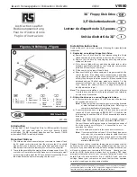
V9580
Brand: RS Pages: 4
RF-4755732
Brand: Renkforce Pages: 4
QumeTrak 242
Brand: Qume Pages: 90
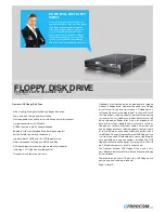
FLOPPY DISK DRIVE
Brand: Freecom Pages: 2
IO-FMP220
Brand: Koutech Pages: 13
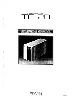
TF-20
Brand: Epson Pages: 79
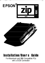
Zip-100
Brand: Epson Pages: 23

Modular Floppy Disk Drive
Brand: Fujitsu Pages: 8
MP-1802
Brand: Hitachi Pages: 92
FB-100
Brand: Brother Pages: 4
M255XK
Brand: Fujitsu Pages: 94
1.44MB Floppy
Brand: HI-VAL Pages: 6
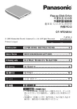
CF-VFD Series
Brand: Panasonic Pages: 8
CF-VFDU03U - 1.44 MB Floppy Disk Drive
Brand: Panasonic Pages: 16

CF-VFDU03W
Brand: Panasonic Pages: 8


