background image

Installation Guide

Summary of Contents for ELPHD02

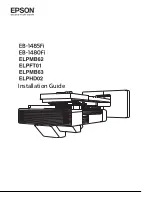
Page 1: ...Installation Guide ...

Page 2: ... short throw projector EB 1485Fi EB 1480Fi using the wall mount ELPMB62 Installing the Touch Unit ELPFT01 Installing the Touch Unit using the touch unit bracket ELPMB63 Installing the Control Pad ELPHD02 Installing the Pen Stand Equipment and mounts brackets that are not included can be purchased as optional accessories ...

Page 3: ...fications 24 External dimensions 25 Adjustment range 27 Vertical slide 27 Horizontal slide 28 Forward backward slide 28 Mini PC installation plate 29 Installation Procedure for the Wall Mount 30 Installing the Bracket 31 Determining the installation position projection distance tables 31 Attaching the adjustment unit to the projector 43 Install the wall plate on the wall 45 Attaching the setting p...

Page 4: ...108 Turning on the Touch Unit 109 Adjusting the Angle of the Laser Touch Unit Auto Setup 110 When auto adjustment fails 116 Calibrating the touch operation position 119 Setting the Projector Batch Setup Function 122 Setup Using a USB flash drive 122 Saving settings to the USB flash drive 122 Copying saved settings to other projectors 123 Setup by Connecting the Computer and Projector with a USB Ca...

Page 5: ...raphical symbols to show how to use this product safely The indications and their meaning are as follows Make sure you understand them properly before reading the guide Symbol Explanation Warning This symbol indicates information that if ignored could possibly result in personal injury or even death due to incorrect handling Caution This symbol indicates information that if ignored could possibly ...

Page 6: ... Package Contents Confirm that you have all necessary items before beginning installation Wall mount Main Mount M4 x 12mm No Part name End cap Adjustment unit Setting plate Wall plate Wall plate cover Hexagonal axis ...

Page 7: ...es after performing wiring Masking sticker Stick this over the groove in the arm of setting plate to cover it up after instal ling Safety wire set Connect to the wall mount and the projectortopreventtheprojectorfrom falling See the user s guide supplied withthesafetywiresetformoredetails Hexagon wrench for M4 No 13 open ended spanner for M8 and M6 No 6 for hexagonal axis M4 x 12 mm hexagon sock et...

Page 8: ... the wall plate at least x4 M10 screw for securing the wall plate temporarily x1 Make sure you prepare cables to connect the projector to devices such as mini PCs in advance For details on the cable connections for your devices see the projector s User s Guide on the Document CD ROM Touch Unit Part Name Application Touch Unit Template sheet for secur ing the Touch Unit Attach this to the wall befo...

Page 9: ... securing the Touch Unit with screws prepare two commercially available M4 screws Touch Unit Bracket Use this when attaching the Touch Unit to outside of the projection surface Part Name Application Touch Unit Bracket Template sheet for Touch Unit Bracket Attach this to the wall before attaching the Touch Unit Bracket and use it to drill necessary holes M4x25mmhexagonsocket head cap bolts x2 Secur...

Page 10: ...apter AC adapter holder Secure the AC adapter to the wall USB cable approx 1 8 m Connects the Control Pad to the com puter Items to prepare in addition to items supplied with the product Use commercially available M4 x 20 mm screws x4 to secure the Control Pad to the wall Pen stand Part Name Application Main unit ...

Page 11: ... the pen stand Spacers for screw holes x3 Attach them to the screw hole when securing the pen stand with screws Items to prepare in addition to items supplied with the product When securing the pen stand with screws prepare commercially available M4 x 20 mm screws x2 ...

Page 12: ...d peripheral devices in the following order a Mount projector on wall and adjust the projected image s p 18 b Install the Control Pad s p 73 c Install the pen stand s p 82 d Perform pen calibration s p 86 e Install and adjust touch unit and perform finger touch calibration s p 90 ...

Page 13: ...nstall the Control Pad s p 73 c Install the pen stand s p 82 d Calibrate the Interactive Pen s p 86 e Install and adjust touch unit and perform finger touch calibration s p 90 f Select Multi Projection settings s p 128 g Calibrate the Interactive Pen s p 86 h Calibrating touch function operations s p 119 ...

Page 14: ...nd remove the projector When using the Touch Unit install the projector so that there is a gap between the projected image and the edges of the screen as shown in the following image 100mm 5 7 50mm 20 50mm 16 6 21 9 20mm 100mm 100mm When projecting a screen with multiple projectors use the Edge Blending function to create a seamless image When projecting a screen with an aspect ratio of 3 1 set th...

Page 15: ...troduction 14 600 c If you cannot set the Blend Range to 600 you can also set it to a value that is less than 600 If you set a value less than 600 black bands may appear on the left and right of the image ...

Page 16: ... Unit and the Control Pad You need the following cables when using the Touch Unit and the Control Pad Prepare a commercially available LAN cable and USB cable to connect the projector and the Control Pad 1080p60p Max 70m CAT6a CAT7 4K30p Max 40m CAT6a CAT7 ...

Page 17: ... interactive function c When two projectors are installed side by side you can only use interactive mouse operations When drawing on the projection screen use the drawing application Easy Interactive Tools You can download this from the following Website http epson sn Max 5m When not using the interactive function You can install two to four projectors when not using the interactive function The f...

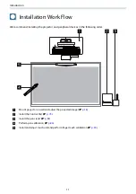
Page 18: ...Introduction 17 Max 5m Max 5m ...

Page 19: ... the projector or mounting surface If this product falls it could cause death or personal injury When installing on a wall install so that it can sufficiently support the mass of the projector and the Wall mount and resist any horizontal vibration Use M10 or 3 8 inch x 60 mm nuts and bolts Nuts and bolts smaller than M10 or 3 8 inch x 60 mm could cause the setting plate to fall Epson accepts no re...

Page 20: ... not interfered with the nuts and bolts Incorrect handling of the cables may cause fire or electric shock When turning on the projector do not look into the projection lens This could cause damage to eyesight due to the powerful light emitted Take particular care when there are children present When turning on the projector at a distance using the remote control make sure there is no one looking i...

Page 21: ...laser beam emitted from the projection lens while projecting Based on IEC EN60825 1 2014 For North South America This projector is a Class 2 laser product that complies with the IEC EN60825 1 2007 international standard for lasers Complies with FDA performance standards for laser products except for deviations pursuant to Laser Notice No 50 dated June 24 2007 ...

Page 22: ...ourprojector model may be exceeded Such an environment may damage the projector Install this product in a place free from excessive dust and humidity to prevent the lens or optical components from becoming dirty Do not use excessive force when adjusting this product This product may break resulting in personal injury This projector is a Class 1 laser product that complies with the IEC EN60825 1 20...

Page 23: ...nteractivefunctionmaynotoperate correctly Carry out power supply wiring work at the installation location of the projector in advance Install the projector away from other electric devices such as fluorescent lights or air con ditioners Some types of fluorescent lights could interfere with the remote control or the pen Wheninstallingtheprojector makesurethereisagapbetweenthewallandtheprojector s a...

Page 24: ... approx 20mminalldirections andinstalled approximately 400 mm from the exhaust vent and 200 mm from the intake vents 400mm 200mm Install the projector so that it is tilted at an angle of no more than 3 degrees or 3 degrees vertically and horizontally in relation to the screen Whenusinginteractivefunctions installtheprojectorsothattheprojectedimageiswithin reach It is recommended to keep connection...

Page 25: ... the Wall mount 24 Wall Mount Specifications Item Specification Wall mount mass setting plate hexagonal axis adjustment unit wall plate wall plate cover end cap Approx 9 2 kg Maximum load capacity Approx 15 0 kg ...

Page 26: ...Installing the Wall mount 25 External dimensions 550 458 LENS CENTER 280 27 5 125 134 160 8 223 5 338 5 418 5 75 233 375 160 630 70 ...

Page 27: ...Installing the Wall mount 26 30 5 31 8 496 234 8 192 2 4 x M4 208 5 74 117 112 25 41 1 35 7 48 2 891 508 162 26 12 20 5 3 125 9 2 x M4 ...

Page 28: ... mount 27 496 234 8 138 8 79 130 2 186 4 192 2 8 5 81 81 120 5 17 5 23 2 35 7 28 3 47 8 10 2 130 130 103 103 8 x M4 10 2 10 5 10 5 24 99 110 131 116 99 24 45 45 10 2 24 60 110 131 116 Adjustment range Vertical slide 40 40 ...

Page 29: ...Installing the Wall mount 28 Horizontal slide 45 45 Forward backward slide 0 383 ...

Page 30: ...Φ3 8 102 116 100 75 14 7 22 7 35 2 130 145 5 21 7 7 7 8 7 150 8 138 8 5 6 75 100 20 2 32 7 Item Specification Screw holes for installing PC VESA compliant 75 mm x 75 mm 100 mm x 100 mm Supported PC sizes Within 150 mm x 150 mm x 44 mm Supported PC weight 0 7 kg or less ...

Page 31: ...ojection distance tables to determine the installation position s p 31 b Attach the adjustment unit to the projector s p 43 c Install the wall plate on the wall s p 45 d Adjust the arm length of the setting plate and then attach it to the wall plate s p 47 e Attach the adjustment unit to the setting plate and then connect the cables and peripheral devices s p 51 f Adjust the position of the image ...

Page 32: ...he value when the setting plate is in the middle of the wall plate See in the following illustration S a c d b x x a Projection distance Minimum Wide to Maximum Tele c Distance from the top edge of the image to the installation screw hole for the wall plate at the bottom b Number on the arm slide scale on the set ting plate d Distance from the top edge of the image to the temporary screw hole for ...

Page 33: ...g the Wall mount 32 See the following for the values of c and d when projecting at an aspect ratio of 16 6 or 21 9 c1 d1 When Screen Position is in the middle c2 d2 When Screen Position is at the top c2 d2 c1 d1 ...

Page 34: ...47 177 328 167 318 206 398 69 1528 859 183 336 173 326 207 399 70 1550 872 190 345 180 335 209 401 71 1572 884 196 353 186 343 210 402 72 1594 897 202 362 192 352 212 404 73 1616 909 209 370 199 360 214 406 74 1638 921 215 379 205 369 215 407 75 1660 934 221 211 217 409 76 1682 946 228 218 219 411 77 1705 959 234 224 220 412 78 1727 971 240 230 222 414 79 1749 984 247 237 223 415 S ...

Page 35: ...291 194 235 427 87 1926 1083 297 200 236 428 88 1948 1096 304 207 238 430 89 1970 1108 310 213 240 432 90 1992 1121 316 219 241 433 91 2015 1133 323 226 243 435 92 2037 1146 329 232 245 437 93 2059 1158 335 238 246 438 94 2081 1171 342 245 248 440 95 2103 1183 348 251 249 441 96 2125 1195 354 257 251 443 97 2147 1208 361 264 253 445 98 2170 1220 367 270 254 446 99 2192 1233 373 276 256 448 100 221...

Page 36: ...09 401 66 1422 888 198 356 188 346 211 403 67 1443 902 205 366 195 356 213 405 68 1465 915 212 375 202 365 215 407 69 1486 929 219 384 209 374 216 408 70 1508 942 226 393 216 383 218 410 71 1529 956 232 403 222 393 220 412 72 1551 969 239 412 229 402 222 414 73 1572 983 246 421 236 411 223 415 74 1594 996 253 430 243 420 225 417 75 1615 1010 260 250 227 419 76 1637 1023 267 257 229 421 77 1659 103...

Page 37: ... 335 238 246 438 87 1874 1171 342 245 248 440 88 1895 1185 349 252 250 442 89 1917 1198 356 259 251 443 90 1939 1212 363 266 253 445 91 1960 1225 369 272 255 447 92 1982 1239 376 279 257 449 93 2003 1252 383 286 258 450 94 2025 1265 390 293 260 452 95 2046 1279 397 300 262 454 96 2068 1292 404 307 264 456 97 2089 1306 410 313 265 457 98 2111 1319 417 320 267 459 99 2132 1333 424 327 269 461 100 21...

Page 38: ... 410 63 1280 960 235 406 225 396 220 412 64 1300 975 242 416 232 406 222 414 65 1321 991 250 426 240 416 224 416 66 1341 1006 258 437 248 427 226 418 67 1361 1021 266 447 256 437 228 420 68 1382 1036 273 458 263 448 230 422 69 1402 1052 281 468 271 458 232 424 70 1422 1067 289 479 279 469 234 426 71 1443 1082 297 489 287 479 236 428 72 1463 1097 304 500 294 490 238 430 73 1483 1113 312 510 302 500...

Page 39: ...8 87 1768 1326 421 324 268 460 88 1788 1341 428 331 270 462 89 1808 1356 436 339 272 464 90 1829 1372 444 347 274 466 91 1849 1387 452 355 276 468 92 1869 1402 459 362 278 470 93 1890 1417 467 370 280 472 94 1910 1433 475 378 282 474 95 1930 1448 483 386 284 476 96 1951 1463 490 393 286 478 97 1971 1478 498 401 288 480 98 1991 1494 506 409 290 482 99 2012 1509 514 417 292 484 100 2032 1524 521 424...

Page 40: ...62 192 352 361 553 212 404 68 1617 606 209 371 199 361 365 557 214 406 69 1641 615 216 380 206 370 369 561 215 407 70 1665 624 223 389 213 379 373 565 217 409 71 1689 633 229 398 219 388 377 569 219 411 72 1712 642 236 408 226 398 381 573 221 413 73 1736 651 243 417 233 407 385 577 222 414 74 1760 660 250 426 240 416 389 581 224 416 75 1784 669 257 435 247 425 393 585 226 418 76 1807 678 263 444 2...

Page 41: ...31 536 234 439 437 629 245 437 87 2069 776 338 545 241 448 441 633 247 439 88 2093 785 345 555 248 458 445 637 249 441 89 2117 794 352 564 255 467 449 641 251 443 90 2140 803 359 262 453 645 252 444 91 2164 812 365 268 457 649 254 446 92 2188 821 372 275 461 653 256 448 93 2212 829 379 282 465 657 258 450 94 2236 838 386 289 469 661 260 452 95 2259 847 393 296 473 665 261 453 96 2283 856 400 303 4...

Page 42: ...4 474 377 520 712 282 474 108 2569 963 481 384 524 716 283 475 109 2592 972 488 391 528 720 285 477 110 2616 981 495 398 532 724 287 479 111 2640 990 502 405 536 728 289 481 112 2664 999 508 411 540 732 290 482 113 2687 1008 515 418 544 736 292 484 114 2711 1017 522 425 548 740 294 486 115 2735 1026 529 432 552 744 296 488 116 2759 1035 536 439 556 748 297 489 117 2783 1043 542 445 560 752 299 491...

Page 43: ...350 184 340 315 507 210 402 68 1588 680 201 359 191 349 318 510 212 404 69 1611 690 207 368 197 358 321 513 213 405 70 1634 700 214 378 204 368 324 516 215 407 71 1658 710 221 387 211 377 328 520 217 409 72 1681 720 227 396 217 386 331 523 219 411 73 1704 730 234 405 224 395 334 526 220 412 74 1728 740 241 414 231 404 338 530 222 414 75 1751 750 247 237 341 533 224 416 76 1774 760 254 244 344 536 ...

Page 44: ...5 246 438 89 2078 890 341 244 387 579 248 440 90 2101 900 347 250 390 582 249 441 91 2125 911 354 257 393 585 251 443 92 2148 921 361 264 396 588 252 444 93 2171 931 367 270 400 592 255 447 94 2195 941 374 277 403 595 256 448 95 2218 951 381 284 406 598 257 449 96 2241 961 388 291 410 602 260 452 97 2265 971 394 297 413 605 261 453 98 2288 981 401 304 416 608 263 455 99 2311 991 408 311 419 611 26...

Page 45: ...4 b Loosen the M4 bolt on the adjustment unit and then align the marks for each part When the position is correct tighten the M4 bolt c Secure the adjustment unit to the base of the projector with the M4 x 12 mm bolts x4 supplied ...

Page 46: ...firmed using the projection distance table p 31 b Drive a commercially available M10 screw into the position of the temporary screw hole for the wall plate Leave a gap of 6 mm or more between the wall and the screw head c Determine the positions for the mounting holes for the wall plate From the screw holes shown in the figure below secure at least four points for optimum balance ...

Page 47: ...m M10 or 10mm 3 8 inch 45mm Pilot hole depth 45 mm Anchor hole depth 40 mm e Remove the template sheet f Place the wall plate on the temporary M10 screw that you installed in step 2 g Use commercially available M10 or 3 8 inch x 60 mm anchor bolts to secure the wall plate to the holes you drilled in step 4 ...

Page 48: ...e M4 x 12 mm bolts x2 and extend the arm slide on the setting plate Adjust the scale on the slider to the combined distance of the value for b confirmed in the projection distance table p 31 and the thickness of the projection surface x b Insert the hexagonal axis into the setting plate ...

Page 49: ...est of the cable over the setting plate They could fall and cause an accident c The following connection ports should be routed so that they come out of the lower part of the setting plate and not through walls Cable for connecting to the Touch Unit Cables for connecting to peripheral devices such as mini PCs ...

Page 50: ...late to the wall plate Insert the hexagonal axis until the tip extends slightly out of the top of the wall plate and the other end connects to the bottom of the wall plate Caution Take care not to trap the cables between the setting plate and wall plate ...

Page 51: ...all mount 50 e Temporarily secure the setting plate Secure three points with the M6 screws supplied x3 f Adjust the vertical slide with the open ended spanner to align the marks on the wall plate and the setting plate ...

Page 52: ...the installation position for the adjustment unit The installation position is marked on the setting plate Install at an appropriate position according to the size of the screen you want to project on to When a projected image is smaller than 80 inches Install the unit at the mark When a projected image is 80 inches or more Install the unit at the mark ...

Page 53: ... the power cord last Attaching peripheral devices Attaching external tuners and accessories Use commercially available M4 screws to secure external tuners and accessories to the screw holes as shown in the following figure Attaching a mini PC or stick PC Attach the mini PC or stick PC to the mini PC plate and secure it to the left or right side of the wall plate ...

Page 54: ...t blocked We recommend installing the PC so that the air exhaust vents are at the top and the air intake vents are at the bottom When securing with the mini PC belt a Wrap the belt around the mini PC plate b Secure the mini PC plate to the wall plate using the M3 x 6 mm screws x4 supplied ...

Page 55: ... and the orientation of the screw holes the order in which parts are installed differs Be sure to check the installation instructions in advance Installation example Secure the mini PC plate with the PC installed to the wall plate using the M3 x 6 mm screws x4 supplied Secure the mini PC plate to the wall plate using the M3 x 6 mm screws x4 supplied and then install the PC ...

Page 56: ...c projector hold down the ID button on the remote control and press the button with the same number as the projector ID Auto Screen Adjustment p 58 Attach corner markers to the four corners of the projection position to automatically adjust the position of the image This is useful when you want to perform an approximate adjustment to a specific position Adjusting using the Setting Plate Installati...

Page 57: ...c Images are not stable immediately after turning on the projector After starting projection wait for at least 30 minutes before adjusting the image When setting up multiple projectors using the batch setup function perform the batch setup before adjusting the projected image We recommend the mechanical position adjustment of the setting plate to adjust the image when you want to maintain image qu...

Page 58: ...t Screen Type from the Installation menu to set the aspect ratio of the projected image e Change the aspect ratio if necessary Project images from a connected device and then press the Aspect button on the remote control Each time you press the button you see the aspect name on the screen and the aspect ratio changes c The aspect ratio does not change when no images are being projected from the co...

Page 59: ...creen Adjustment A flat projection surface No patterns dirt or obstacles on the projection surface Before performing the Auto Screen Adjustment set the Screen Type setting first If you change the Screen Type after performing Auto Screen Adjustment the adjustments will be reset a Place the corner markers at the four corners of the position you want to project to c Corner markers cannot be placed ag...

Page 60: ... the Menu button Using the Remote Control Using the Control Panel c Select Auto Screen Adjustment from the Installation menu You see the guidance screen for Auto Screen Adjustment d Loosen all of the adjustment dials and adjustment screws ...

Page 61: ... screen overlap with the corner markers Make sure that all of the corner markers are within the yellow areas f When you determine the position tighten all of the adjustment dials and adjustment screws that you loosened in step 4 Warning Tighten all bolts and screws firmly Otherwise the product may fall and cause personal injury or property damage ...

Page 62: ...her adjustments Using Arc Correction or Point Correction returns the image to the status before auto correction was performed Performing mechanical adjustment using the Setting Plate Installation Guide Use the guidance screen to adjust the position of the image a Press the Menu button Using the Remote Control Using the Control Panel b Select Setting Plate Installation Guide from the Installation m...

Page 63: ...al in the installation guide to adjust the horizontal roll d Loosen the M4 screw and then turn the adjustment dial in the installation guide to adjust the horizontal rotation e Turn the adjustment dial in the installation guide to adjust the vertical tilt ...

Page 64: ...Installing the Wall mount 63 f Loosen the M4 bolt and then adjust the horizontal slide g Loosen the M4 bolts x2 and then adjust the forward backward slide ...

Page 65: ...property damage j Adjust the focus of position A in the following figure k When you have finished making adjustments press the Esc button on the remote control or the control panel to exit the guidance screen Adjusting using the projector menus c You can save adjusted values in Memory from the Geometry Correction menu Beforeperformingtheadjustment settheScreenTypesetting first IfyouchangetheScreen...

Page 66: ...Installing the Wall mount 65 Arc Correction a Press the Menu button Using the Remote Control Using the Control Panel b Select Geometry Correction from the Installation menu c Select Arc Correction ...

Page 67: ... a range that cannot be adjusted you see the message Cannot adjust any further displayed e When you have finished making adjustments press the Esc button on the remote control or the control panel to finish adjustment Quick Corner a Press the Menu button Using the Remote Control Using the Control Panel ...

Page 68: ...Installing the Wall mount 67 b Select Geometry Correction from the Installation menu c Select Quick Corner ...

Page 69: ... adjust any further displayed c While adjusting the sides press buttons 1 3 7 and 9 on the remote control to select the side you want to adjust e When you have finished making adjustments press the Esc button on the remote control or the control panel to finish adjustment Point Correction a Press the Menu button Using the Remote Control Using the Control Panel ...

Page 70: ...Installing the Wall mount 69 b Select Geometry Correction from the Installation menu c Select Point Correction d Select Point Correction and then select the number of grid ...

Page 71: ... adjustment c If it is hard to see the grid use Pattern Color to change the color of the grid f When you have finished making adjustments press the Esc button on the remote control or the control panel to finish adjustment Attaching the covers a Attach the left wall plate cover ...

Page 72: ...Installing the Wall mount 71 b Attach the right wall plate cover c Fit the end cap to the setting plate c If you are concerned about the groove in the arm stick the supplied masking sticker ...

Page 73: ...ll a commercially available theft prevention wire lock Pass the wire lock through the security cable installation points on the projector and the setting plate Install a security wire from Kensington The security slot on this product is compatible with the Microsaver Security System manufactured by Kensington See the following for more details on the Microsaver Security System http www kensington ...

Page 74: ...o occur Do not pull on the AC adapter s cable or place heavy items on the cable Do not modify the power cable Otherwise it may cause fire or electric shock Do not apply strong force or shocks to the AC adapter such as stepping on it dropping it or striking it This could cause damage If the AC adapter is damaged turn off the control pad unplug the power plug from the power outlet and contact your l...

Page 75: ...n a confined location or cover itwith a cloth and so on except for the AC adapter holder supplied Otherwise the AC adapter may become hot and cause burns or unexpected accidents Do not wrap the power cable around the AC adapter Failure to do so may cause it to disconnect or overheat Do not disassemble or remodel the control pad Beforecleaning makesureyouunplugtheACadapterandthepowerplugfromthepowe...

Page 76: ...equipment has been tested and found to comply with the limits for a Class B digital device pursuant to Part 15 of the FCC Rules These limits are designed to provide reasonable protection against harmful interference in a residential installation This equipment generates uses and can radiate radio frequency energy and if not installed and used in accordance with the instructions may cause interfere...

Page 77: ...Installing the Control Pad 76 For Canadian Users ...

Page 78: ... 2 5 A 30 W Electricity consumption during use 4 5 W Operating temperature 0 to 40 C no condensation Operating altitudes 0 to 3 048 m External dimensions Unit mm 39 5 36 5 174 29 116 95 198 201 8 42 8 21 5 17 5 40 4 x M4 Cable routing holes You can use either of the cable openings indicated in Route the power cable along the groove at the back of the Control Pad ...

Page 79: ...Installing the Control Pad 78 ...

Page 80: ...Installing the Control Pad 79 Installing the Control Pad a Place your finger in the hole at the top and remove the front cover b Connect the power cable and route the cable down the back ...

Page 81: ... screwing make sure they are not tilted at an angle to the installation surface Make sure that the Control Pad is secured properly Do not use double sided tape or magnets to secure the Control Pad c We recommend checking the operation of the Control Pad before securing with screws d Secure the AC adapter to the wall using M4 screws x4 ...

Page 82: ...e AC adapter in the holder and connect it to the power supply f Connect the cable that is connected to the projector to the Control Pad See Connecting the Touch Unit and the Control Pad p 15 for details on connecting g Attach the front cover ...

Page 83: ...rference which may cause med ical equipment to malfunction Caution Do not go near the pen stand with magnetic storage media such as magnetic cards or precision electronic devices such as computers digital watches or mobile phones A powerful magnet within the unit could corrupt data or cause a malfunction The magnet on the back of the pen stand exerts a powerful magnetic attraction on the installat...

Page 84: ...Installing the pen stand 83 Pen Stand Specifications Item Specification Pen stand mass Approx 93 g External dimensions Unit mm 101 9 36 7 10 2 28 8 99 9 44 4 28 8 2 x M4 70 ...

Page 85: ...e M4 screws When securing with magnets a Check the installation position and secure with magnets Caution Powerful magnets are used which can cause injury if you trap your fingers Be careful not to trap your fingers or any other part of your body between the magnets and the installation surface b Attach the cover ...

Page 86: ...s a Check the installation position and secure with commercially available M4 screws 20 mm x2 Warning When screwing make sure they are not tilted at an angle to the installation surface Make sure that the pen stand is secured properly b Attach the cover ...

Page 87: ...d time and after perform Auto Calibration p 88 c When the Screen Type is set to 16 6 replace the soft pen tip with a hard pen tip Manual Calibration a Turn on the projector and then press the Menu button Using the Remote Control Using the Control Panel b Select Manual Calibration from the Pen Touch menu c When multiple projectors are installed in parallel you see a message prompting you to tempora...

Page 88: ...t Yes You see a green dot at the top left of the projection screen d Touch the center of the dot with the pen tip of the interactive pen The dot disappears and moves to the next position c Make sure you touch the center of the dot Otherwise it may not be positioned correctly ...

Page 89: ... is complete c Check that there are no obstacles between the interactive pen and the Interactive pen receiver shown below If you touch the wrong position press the Esc button on the remote control to return to the previous dot To cancel calibration hold down the Esc button for two seconds Auto Calibration a Turn on the projector and then press the Menu button Using the Remote Control Using the Con...

Page 90: ...hide the image for the projector installed next to it When you see this message press the A V Mute button to hide the image from the next projector c Check that the pattern image fits into the projected image and then select Yes Pen calibration starts automatically c If Auto Calibration fails follow the on screen instructions to check your surroundings Or perform Manual Calibration ...

Page 91: ...magnet within the unit generates electromagnetic interference which may cause med ical equipment to malfunction Caution Do not go near the Touch Unit with magnetic storage media such as magnetic cards or precision electronic devices such as computers digital watches or mobile phones A powerful magnet within the unit could corrupt data or cause a malfunction The magnet on the back of the Touch Unit...

Page 92: ...e limits for a Class B digital device pursuant to Part 15 of the FCC Rules These limits are designed to provide reasonable protection against harmful interference in a residential installation This equipment generates uses and can radiate radio frequency energy and if not installed and used in accordance with the instructions may cause harmful interference to radio communications However there is ...

Page 93: ...talled on a different surface Secure with the Touch Unit Bracket Caution When using the Touch Unit images should be projected onto the front of the screen You cannot use finger touch operations when images are projected onto the rear of the screen Before installing the Touch Unit make sure that the installation surface is not warped or distorted and that any unevenness on the screen surface is les...

Page 94: ...hickness of the top of the frame is less than 3 mm If the thickness of the top of the screen exceeds 3 mm the Touch Unit will not operate correctly 0 3mm Make sure that the distance from the wall to the surface of the screen is less than 50 mm You cannot install the Touch Unit Bracket if the distance is more than 50 mm 15 50mm ...

Page 95: ...the Touch Unit to indicate that it is a Class 1 laser product For American Users The labels contain the following information Class 1 laser product Warning Do not open the case The device contains a high power laser product Warning Caution If this section is opened class 3B invisible laser radiation will be emitted Avoid exposure to the radiation beams Laser diffusion port The laser beam is diffus...

Page 96: ...Installing the Touch Unit 95 Wavelength 932 to 952 nm ...

Page 97: ...ations Item Specification Touch unit mass Approx 0 6 kg Operating temperature 0 to 40 C Power supplied from the projector 5 VDC 0 65 A External dimensions 422 64 8 177 59 52 52 36 128 160 160 36 59 177 8 3 9 3 16 2 39 6 19 1 45 4 8 14 38 2 19 2 x M4 ...

Page 98: ...uch Unit Bracket Specifications Item Specification Touch unit bracket mass Approx 1 8 kg Maximum load capacity Approx 8 8 kg External dimensions 61 220 90 4 2 18 35 35 35 90 90 160 231 484 242 72 5 86 242 76 4 2 11 5 231 160 220 4 2 ...

Page 99: ...Installing the Touch Unit 98 Adjustment range 79 5 140 5 15 76 ...

Page 100: ...frared deflectors to any obstacles such as a frame or tray at the bottom of the projection surface If there are any obstacles the laser is reflected as shown below and the location of your finger will not be detected correctly a Stick the supplied infrared deflectors along the locations of the obstacles ...

Page 101: ...he Touch Unit When installing on the projection surface without using the Touch Unit Bracket a Turn on the projector and then press the Menu button Using the Remote Control Using the Control Panel b Select Touch Unit from the Installation menu ...

Page 102: ... attach the touch unit with magnets When installing on a non magnetic surface go to the next step Caution Powerful magnets are used which can cause injury if you trap your fingers Be careful not to trap your fingers or any other part of your body between the magnets and the installation surface 5 7 50mm 20 50mm 16 6 21 9 After you attach the Touch Unit go to Turning on the Touch Unit p 109 ...

Page 103: ...tallation position As shown below attach the bottom of the template sheet onto the installation pattern f Drill holes in the installation surface and then remove the template sheet g Attach the spacers supplied x2 to the screw holes on the back of the Touch Unit h Remove the rubber caps x2 from the front of the Touch Unit ...

Page 104: ...f the screw holes in the Touch Unit 20 4mm j Attach the rubber caps that you removed in step 8 to the screw holes on the front of the Touch Unit When using the Touch Unit Bracket to install outside of the projection surface a Turn on the projector and then press the Menu button Using the Remote Control Using the Control Panel ...

Page 105: ...Installing the Touch Unit 104 b Select Touch Unit from the Installation menu c Select Installation Pattern You see the installation pattern on the projected image ...

Page 106: ... and the projection surface we recommend drawing marks in advance at the attachment position e Drill holes in the installation surface and then remove the template sheet Make holes at the four points labeled as Main on the template sheet c Depending on the condition of the installation surface you may need to secure the bracket at the points labeled as Sub Make holes at four points two on the left...

Page 107: ...nt of the bracket forward until they are fully extended To prevent the sliding section from slipping during installation lightly tighten the top screws x2 that you loosened in step 6 h Secure the bracket to the wall with commercially available 3 8 mm diameter wood screws with a length of 45 mm x4 or M4 anchor bolts x4 ...

Page 108: ...Touch Unit 107 i Slide the bracket so that it fits with the projection screen Slide it in until the lower edge of the bracket touches the projection screen j Remove the rubber caps x2 from the front of the Touch Unit ...

Page 109: ...hand between the Touch Unit and the Touch Unit Bracket l Attach the rubber caps that you removed in step 10 to the screw holes on the front of the Touch Unit Attaching a Security Cable The security slot on the Touch Unit is compatible with the Microsaver Security System manufactured by Kensington See the following for more details on the Microsaver Security System http www kensington com ...

Page 110: ...able that is connected to the projector to the TCH port on the Touch Unit b Select Touch Unit from the Installation menu c Set Power to On The Touch Unit turns on and the indicator is lit blue c The Touch Unit automatically turns on the next time you turn on the projector if Power is set to On ...

Page 111: ...ce thereby detecting the finger position allowing the projector s infrared camera to recognize the position being reflected Adjust the angle of the laser light coming from the Touch Unit so that the projector can correctly detect the position of your finger If the laser is not emitted parallel to the screen the projector will not detect touch operations or the position of your finger correctly Whe...

Page 112: ...or enters a state in which a touch is still being detected and a click operation is not recognized c Check the following before adjusting the angle of the laser The Interactive Pen calibration has been performed s p 86 The Edge Blending setting is turned off When Edge Blending is set to On angle adjustment for the laser may fail Temporarily set Edge Blending to Off re calibrate the pen and then ad...

Page 113: ...side follow the on screen instructions to set Installation Touch Unit Power to Off for the next projector d Select whether or not the Touch Unit Bracket is being used e IfyouareusingtheTouchUnitBracket turntheadjustmentscrewonthetopofthebracket counterclockwise until you cannot turn it any further ...

Page 114: ...rkers near the projected image during angle adjustment If other objects are on the projected image angle adjustment may not be performed correctly g Press the Enter button to start Touch Unit auto adjustment c Auto adjustment may take a few minutes depending on the projection surface h When the message Touch Unit adjustment complete is displayed remove the markers from the projection surface If yo...

Page 115: ...s displayed in a different location to the point you touched select Up once using the control panel or the remote control Next touch again with your finger to confirm Repeat until is displayed in the correct posi tion Adjustment is complete when appears in the correct position for all four positions Go to Calibrating the touch operation position p 119 j When multiple projectors are installed on th...

Page 116: ... the Touch Unit 115 k Follow the instructions displayed on the screen of the next projector and then press Down or Up Adjustment is complete when no instructions are displayed on the screen of the next projector ...

Page 117: ...hat the Touch Unit installation position is correct Make sure that the Touch Unit and the projected image are parallel If you are using a Touch Unit Bracket make sure that the bottom edge of the bracket is flush with the edge of the projection surface without any gaps ...

Page 118: ...m the projection surface Ifyouseeanicon ontheprojectionsurface check if there are any obstacles at the position of the icon Check if the strong light such as sunlight or fluo rescent light is shining onto the projection sur face or the interactive light receiver When you have checked everything perform Touch Unit Setup from the Installation menu The Touch Unit may be malfunctioning Contact your de...

Page 119: ... Touch Unit 118 a Press the Enter button You see the following adjustment screen b Turn the adjustment screw clockwise to cover the left and right pointers c Press the Enter button to start Touch Unit auto adjustment ...

Page 120: ...message notifying you that auto adjustment has failed check When auto adjustment fails p 116 Calibrating the touch operation position Perform touch calibration so that the projector can recognize touch operations precisely a Press the projector s Menu button Using the Remote Control Using the Control Panel b Select Touch Unit from the Installation menu ...

Page 121: ...ft of the projection screen e Touch the center of the dot with your finger When the dot disappears and moves to the next position remove your finger c Make sure you touch the center of the dot Otherwise it may not be positioned correctly Do not touch with anything else except the tip of your finger ...

Page 122: ...ete c If you touch the wrong position press the Esc button on the remote control or control panel This returns you to the previous dot You cannot go back by two dots To cancel touch calibration hold down the Esc button for two seconds It may take several seconds after all of the dots have disappeared until touch calibration is complete ...

Page 123: ... position of the projectors The batch setup function copies adjustment values for the projected image such as Geometry Correction If batch setup is performed after adjusting the position of the projectors the adjustments you made may change By using the batch setup function the registered User s Logo is copied to the other projectors Do not register confidential information as the User s Logo Caut...

Page 124: ...l panel connect the power cord to the projector The Power indicator and the Status indicator turn blue and the Laser indicator and the Temp indicator turn orange When all of the projector s indicators turn on release the Esc button When all of the indicators start flashing the batch setup file is being written Caution Do not disconnect the power cord from the projector while the file is being writ...

Page 125: ...l of the indicators start flashing the settings are being written Caution Do not disconnect the power cord from the projector while the settings are being written If the power cord is disconnected the projector may not start correctly Do not disconnect the USB flash drive from the projector while the settings are being written If the USB flash drive is disconnected the projector may not start corr...

Page 126: ...tupfile PJCONFDATA bin tothecomputer c If you need to change the name of the batch setup file add text after PJCONFDATA If you change the PJCONFDATA section of the file name the projector may not be able to recognize the file correctly You can only use single byte characters for the file name e Perform Remove USB device on your computer and then disconnect the USB cable c When using a Mac perform ...

Page 127: ... that you saved to your computer to the top level folder of the removable disk c Do not copy any files or folders other than the batch setup file to the removable disk e Perform Remove USB device on your computer and then disconnect the USB cable c When using a Mac perform Remove EPSON_PJ When all of the indicators start flashing the settings are being written Caution Do not disconnect the power c...

Page 128: ...ectly Disconnect the USB flash drive or the USB cable unplug and then plug in the projector s power cord and then try again Are the Power and the Status indicators blue and the Laser and the Temp indica tors flashing orange quickly Writingthesettingsmayhavefailedandanerrormayhaveoccurred in the projector s firmware Stop using the projector remove the power plug from the electrical outlet and conta...

Page 129: ... s Menu a Connecting cables s p 16 b Setting the Projector ID s p 128 c Multi Projection connection settings s p 130 d HDMI Link settings s p 133 e Multi Projection image adjustment s p 134 When using interactive features in Multi Projection perform the following after making the settings above f Projector Sync Settings s p 135 g EDID settings s p 136 h Calibrate the Interactive Pen s p 86 i Calib...

Page 130: ... Select the ID number for the projector d Press the Esc button to close the menu Repeat steps 1 to 4 for the remaining projectors e Point the remote control at the projector you want to operate and then press the ID button The current ID number is displayed on the projection screen ...

Page 131: ...e control ID is set to 0 you can operate all of the projectors regardless of the projector ID setting Operating multiple remote controls at the same time can cause accidental operations due to infrared interference Multi Projection Connection Settings Make the following settings on all connected projectors The settings differ depending on whether or not you use the interactive functions When using...

Page 132: ...t Process Out Follow the on screen instructions to restart the projector d Set the order Set the projector on the left to 1 and the projector on the right to 2 e Set Connect Computer Set to Yes for the projector connected to the computer If no computer is connected to the projector set to No ...

Page 133: ...s the Menu button Using the Remote Control Using the Control Panel b Select HDMI Out Setting from the Multi Projection menu c Select Pass Through Follow the on screen instructions to restart the projector d Set the Number of Projectors Set the number of connected projectors ...

Page 134: ...ion for the projector on the far left to 1 HDMI Link settings Use HDMI Link to link the power on off function across multiple projectors a Press the Menu button Using the Remote Control Using the Control Panel b Select HDMI Link from the Signal I O c Select HDMI Link ...

Page 135: ... Multi Projection c Images are not stable immediately after turning on the projector After starting projection wait for at least 30 minutes before adjusting the image a Turn on the projector b Pressthe ColorMode buttonontheremotecontrol andthensettheColorModetoMulti Projection c Press the Menu button Using the Remote Control Using the Control Panel ...

Page 136: ...t the brightness of the entire image Select Cus tom andthenadjustthe BrightnessLevelbased onthe darkest projector Color Uniformity Color Matching RGBCMY Adjust the color of the image for each projector so that the entire image looks uniform Projector Sync Settings only when using interactive functions Connect the projectors in advance by using the remote control cable set ELPKC28 For details see C...

Page 137: ...ings only when using interactive functions a Press the Source Search button to switch the source to HDMI or HDBaseT Using the Remote Control Using the Control Panel c EDID settings are saved for each source b Press the Menu button Using the Remote Control Using the Control Panel ...

Page 138: ...Setting the Projector 137 c Select EDID from the Signal I O menu d Select 3240x1080 60Hz ...

Page 139: ...equipment that has risk of electric shock IEC60417 No 5957 For indoor use only To identify electrical equipment designed primarily for indoor use IEC60417 No 5926 Polarity of d c power connector To identify the positive and negative connections the polarity on a piece of equipment to which a d c power supply may be connected IEC60417 No 5001B Battery general On battery powered equipment To identif...

Page 140: ...dicate the equipment has a laser radiation part ISO 3864 Disassembly prohibition Toindicateariskofinjury suchaselectricshock iftheequipment is disassembled IEC60417 No 5266 Standby partial standby To indicate that part of the equipment is in the ready status ISO3864 IEC60417 No 5057 Caution movable parts To indicate that you must keep away from movable parts ac cording to protection standards IEC ...

Page 141: ...oHS Manufacturer SEIKO EPSON CORPORATION Address 3 5 Owa 3 chome Suwa shi Nagano ken 392 8502 Japan Telephone 81 266 52 3131 http www epson com Importer SEIKO EUROPE B V Address Azië building Atlas ArenA Hoogoorddreef 5 1101 BA Amster dam Zuidoost The Netherlands Telephone 31 20 314 5000 http www epson eu ...

Page 142: ...al Notice Mac and OS X are trademarks of Apple Inc MicrosoftandWindowsaretrademarksorregisteredtrademarksofMicrosoftCorporationintheUnitedStates and or other countries 2019 Seiko Epson Corporation 2019 11 413823901ENPDF ...

Reviews: