background image

Technical Reference

Manual

MR Series

English

403308709

Rev. I

EPSON

Summary of Contents for DM-M820

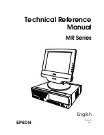
Page 1: ...Technical Reference Manual MR Series English 403308709 Rev I EPSON ...

Page 2: ......

Page 3: ...y unit was changed For IM 800 Ferrite core Ref 220 Reason for change This explanation was missing Rev C 1 7 9 2 2 4 Add the Indiividual Sales of IM and DM vii viii 1 1 6 10 2 4 7 4 Add the AC Adapter OI MR01 1 3 6 11 2 1 6 1 2 Revision of the illustration 3 1 3 Revision of the Hardware diagram 4 1 3 17 19 Add the installation for Windows XP Professional Locally Procured Edition 4 2 Add the explana...

Page 4: ...sket to the FDD unit Reason for change We stop supplying the gasket Appendix B Changed the partslist and Exploded Diagrams The added parts in the list is indicated below Touch panel unit Reference number 115 Reason for change To be changed the composition of the parts Note The parts Touch panel Upper plate Lower plate Touch panel asssembly will be not supplied Because the touch panel unit will be ...

Page 5: ...ock Rev G v vii 1 1 3 4 9 10 2 1 3 5 6 3 1 4 6 8 3 14 15 18 8 23 9 25 30 31 9 51 54 B 16 24 Add the IM 800 with TM Printer Power Supply model 1 1 11 B 2 15 Add the DM M820 High brightness model 9 33 42 Add the notes 9 50 Add the Speaker instdliation B 16 24 Add the COM cable B Rev H 7 1 4 6 9 2 4 27 39 B 11 15 Add the change of LCD Rev I 9 68 70 Add the Cautions Rev Page Description ...

Page 6: ...hird parties as a result of accident misuse or abuse of this product or unauthorized modifications repairs or alterations to this product or excluding the U S failure to strictly comply with Seiko Epson Corporation s operating and maintenance instructions Seiko Epson Corporation shall not be liable against any damages or problems arising from the use of any options or any consumable products other...

Page 7: ...erate For the standard model Unplug the power cable immediately if the IM 800 produces smoke a strange odor or unusual noise Continued use may lead to fire or electric shock Contact your dealer or an EPSON service center for advice Never insert or disconnect the power plug with wet hands Doing so may result in severe shock Do not allow foreign objects to fall into this product Penetration by forei...

Page 8: ...gs all the way in Do not use a damaged cable Regularly remove the power plug from the outlet and clean the base of the prongs and between the prongs If you leave the power plug in the outlet for a long time dust may collect on the base of the prongs causing a short and fire CAUTION When replacing the battery use only an equivalent type battery recommended by the manufacturer If your system has a m...

Page 9: ...ting or fire Be sure to attach all covers after setup If they are not attached foreign matter may enter this product and it may not operate correctly Never clean the product with thinner benzine alcohol or other such solvent Do not use aerosol sprayers containing flammable gas inside or around this product Doing so may cause fire Do not use this product with any voltage other than the specified on...

Page 10: ...so may result improper operation Be sure to set this product on a firm stable horizontal surface The product may break or cause injury if it falls Do not use the unit in locations subject to high humidity or dust levels Excessive humidity and dust may cause equipment damage fire or shock Do not use the unit in locations subject to liquids since this product is not waterproof Do not use the product...

Page 11: ...ug the power cable immediately and then contact your dealer or a SEIKO EPSON service center for advice Continued usage may lead to fire or shock Do not place multiple loads on the power outlet wall outlet Overloading the outlet may lead to fire Always supply power directly from a standard domestic power outlet Handle the power cable with care Improper handling may lead to fire or shock Do not modi...

Page 12: ...rizontal surface Product may break or cause injury if it falls Do not use in locations subject to high humidity or dust levels Excessive humidity and dust may cause equipment damage fire or shock Do not place heavy objects on top of this product Never stand or lean on this product Equipment may fall or collapse causing breakage and possible injury To ensure safety please unplug this product prior ...

Page 13: ...pter 2 Setup for the IM 800 and the DM D820 Chapter 3 Hardware Specifications Chapter 4 OS and Drivers Chapter 5 BIOS Functions Chapter 6 Operation of the IM 800 and the DM D820 Chapter 7 Maintenance and Adjustment Chapter 8 Troubleshooting Chapter 9 Disassembly and Assembly Appendix A Jumper Settings Appendix B Parts Information Name of document Description IM 800 User s Manual Provides informati...

Page 14: ... 1 13 IM 800 1 13 DM M820 1 13 Chapter 2 Setup for the IM 800 and the DM M820 Setting the AC Voltage for the IM 800 For the Standard model 2 1 IM 800 Installation Positions 2 1 Installing the DM M820 2 2 Cable Arrangement 2 2 Connecting the DM M820 2 3 Connector Cables for a DM M820 with a Touch Panel and MSR 2 3 Connector Cables for a DM M820 with a Touch Panel and without an MSR 2 3 Connector Ca...

Page 15: ...3 Installing the MSR Utility for Windows 4 13 Recovering the OS 4 14 Installation for Windows XP Professional Locally Procured Edition 4 16 Installation Procedure 4 16 Installing the Serial Port Driver 4 17 Installing the Touch Panel Driver MSR Utility and the Other Devices 4 18 Installation for Windows 2000 Professional Locally Procured Edition 4 19 Installation Procedure 4 19 Installing the Inte...

Page 16: ...Installing the MSR Utility for MS DOS 4 51 Setting of Windows and Drivers 4 51 Touch Panel Driver for Windows 4 51 Touch Panel Driver for MS DOS 4 72 HDD Power Down Timer Setting 4 73 MSR Utility for Windows 4 77 Automatic Definition Data Setting Utility for Windows 4 79 MSR Utility for MS DOS 4 82 Automatic Definition Data Setting Utility For MS DOS 4 87 Chapter 5 BIOS Functions HDD Power Down Ti...

Page 17: ... 7 1 Determining which procedure to use 7 1 Display Adjustment SERIAL NO xxxx00xxxx 7 2 Display Adjustment SERIAL NO xxxx01xxxx 7 4 Touch Panel Calibration 7 7 Windows 7 7 MS DOS 7 7 Maintenance for AC Adapter 7 8 Chapter 8 Troubleshooting Flow of Troubleshooting Procedures 8 1 Preparations for Troubleshooting 8 2 Problems and Possible Causes 8 2 System Unable to Start 8 3 Power Management Faults ...

Page 18: ... 9 25 Removing the Components Later the SERIAL NO xxxx01xxxx 9 27 MSR Assembly or LED Circuit Board 9 27 Rear Case 9 28 Removing the Front Case 9 29 Rear panel 9 30 Touch Panel Circuit Board 9 31 LCD Circuit Board 9 32 Inverter Circuit Board 9 33 DC Jack Board 9 34 Removing the Touch Panel Assembly 9 35 LCD 9 37 Switch Circuit Board 9 39 Disassembly and Assembly of the IM 800 9 40 Conceptual Work ...

Page 19: ...e Block B 13 DM M820 014 024 114 124 Later the SERIAL NO xxxx01xxxx Component Block B 14 DM M820 014 024 114 124 Later the SERIAL NO xxxx01xxxx Base unit Block B 15 Parts list DM M820 015 025 115 125 SERIAL NO xxxx00xxxx B 16 DM M820 015 025 115 125 SERIAL NO xxxx00xxxx Case Block B 18 DM M820 015 025 115 125 SERIAL NO xxxx00xxxx Component Block B 19 DM M820 015 025 115 125 SERIAL NO xxxx00xxxx Ba...

Page 20: ...xviii Rev I ...

Page 21: ...for 10Base T 100Base TX is installed as standard equipment Four serial interface ports are provided One PCI slot is provided A power supply for a TM printer is provided For the 24V model 1 Cables on the rear of the IM 800 can be covered by the included cable cover A small footprint with maximum dimensions of 315 365 88 mm W D H 12 4 14 4 3 5 including rear cover 1 Applies only with the TM Printer ...

Page 22: ... the DM M820 IM 800 DM M820 The OLD model has 1 light The IM 800 and the DM M820 are sold separately but the DM 820 model with MSR is sold only with the IM 800 CPU 733MHz 1 2GHz HDD One 3 5 HDD Two 2 5 HDDs CD ROM drive CD ROM drive CD R RW drive Without Power Supply For the standardmodel 145W ATX Power supply Power Supply Withe the TM Printer Power Supply model 180W ATX Power supply with 24V Spea...

Page 23: ...nical Reference Manual Part Names for IM 800 USB ports CD FDD cover Power switch Power LED HDD LED Ventilation opening Front view CD ROM drive option FDD LED CD ROM LED CD ROM eject button Eject hole FDD eject button FDD unit With CD FDD cover open ...

Page 24: ...witch Mouse Keyboard COM1 port LPT port Display port USB port Ethernet port Line out output Line in input COM4 port AC Inlet Mic input Rear view 24V model COM2 port PCI slot COM3 port DC 24V output for TM printer Mouse Keyboard COM1 port LPT port Display port USB port Ethernet port Line out output Line in input COM4 port AC Inlet Mic input DC 12V output ...

Page 25: ...Board Assembly HDD Speaker Power Supply PCI card CPU DIMM CD ROM Drive FDD Inside view for the Standard model for the Speaker model Rear Side Front Side COM Port Circuit Board Assembly HDD Speaker Power Supply PCI card CPU DIMM CD ROM Drive FDD Inside view for the 24V model for the Speaker model DC 24V Board ...

Page 26: ...or DM M820 LCD touch panel MSR unit Function control buttons Power switch Adjustment control Power On LED LED for MSR Card Slot Model with MSR LCD touch panel Function control buttons Power switch Adjustment control Power On LED Model without MSR ...

Page 27: ...es Technical Reference Manual LCD stand Stand tab Cable A Cable B Cable C Rear view Display connector DC plug Serial port connector PS 2 keyboard connector for IM 800 PS 2 keyboard connector for keyboard Cable A with a touch panel and an MSR ...

Page 28: ...with a touch panel Applies only to models with an MSR Display connector DC plug Cable B without a touch panel and an MSR Display connecter DC plug Serial port connector Cable C with a touch panel without an MSR AC inlet DC plug Power LED AC Adapter OI MR01 ...

Page 29: ...ce Keyboard One PS 2 type 6 pin mini DIN Mouse One PS 2 type 6 pin mini DIN Serial 3 Four ports 9 pin D sub male 5V or 12V can be output to COM3 or COM4 Parallel One port D sub 25 pin female SPP EPP ECP supported Display One port D sub 15 pin female USB 4 Two ports on the front and two ports on the rear Audio LINE IN LINE OUT microphone terminals DC12V output 5 8 One 12V 3A for DM M820 DC 24V outp...

Page 30: ...argeable battery that supplies the backup voltage to the RTC and the RTC s built in CMOS RAM when AC power is not supplied The battery can be exchanged easily because the battery is connected through the socket Battery type CR2032 Battery life Approximately 5 years Power supply Standard model 145W ATX power supply is built in Input voltage 8 AC input voltage can be changed with a switch Low range ...

Page 31: ...duced to half Backlight Standard model Old Backlight High brightness model Number of lamps 2 lamp Brightness 275 cd m2 min except touch panel Life 50 000 hours or more at 25 5 C 77 9 F Initial brightness reduced to half Touch panel 1 Method Resistive film touch with finger Surface solidity 3H or more JIS K 5400 Positioning accuracy 1 5 maximum MSR 2 Supported cards ISO 7811 JIS X6301 Type I tracks...

Page 32: ...erature 5 to 35 C 41 to 95 F 10 to 50 C 14 to 122 F Humidity RH 30 to 80 non condensing 30 to 90 non condensing The unit is not water resistant Others Connection to the IM 800 through an exclusive DC cable A button on the right side of the panel lets you adjust the backlight brightness Item Specification Input 90 264 VAC 1 5 A max Frequency 47 63 Hz Output 12VDC 3 A max Protection function Over vo...

Page 33: ...Reference Manual Dimensions IM 800 Dimensions 315 W 280 D 88 H mm 12 4 11 3 5 excluding the rear cover 315 W 365 D 88 H mm 12 4 14 4 3 5 including the rear cover DM M820 315 88 excluding the rubber feet Units mm 280 365 340 mm 320 mm 200 mm 305 mm 250 mm ...

Page 34: ... Rev I Underside of Base The dotted circle is the position and size of the hole in the table required if the DM M820 is mounted on a table with the cable going down rather than out of the back of the LCD stand 102 70 200 240 50 ...

Page 35: ...ltage select switch IM 800 Installation Positions WARNING If you set this product upright be sure the ventilation opening is on the top Do not place any object on top of the ventilation opening If the ventilation opening is blocked the product can be damaged by overheating If you install this product horizontally never place any object within 3 cm 1 2 of the ventilation openings on the front side ...

Page 36: ...e Arrangement When you plan your installation of the DM M820 consider the cable that comes out of the base There are two ways you can arrange the cable Make a hole in the surface on which you will place the unit and run the cable through the hole A in the illustration below Remove the tab from the back of the LCD stand and run the cable out of the back of the LCD stand B in the illustration below ...

Page 37: ... not use COM3 or COM4 Also if you are using a DM M820 with a touch panel do not install a mouse driver Installing a mouse driver can prevent the touch panel from working Keyboard out Connects the keyboard out to the IM 800 keyboard port Note Be sure not to connect to the mouse port Keyboard in If you are using an external PS 2 keyboard connect it to the keyboard in connector Connector Cables for a...

Page 38: ...Power Cable for AC Adapter Be sure to push the end of the power cable all the way into the AC inlet The fitting on the power cable should make contact with the back of the inlet CAUTION Do not use the DC plug on a system other than the IM 800 or the OI MR01 AC adapter The DC plug on the exclusive cable is designed only for the IM 800 or the OI MR01 AC adapter IM 800 Connectors The illustration bel...

Page 39: ...he driver CD ROM for the IM 800 included with the IM 800 Either 5 V or 12 V can be output to COM3 or COM4 See Appendix A Jumper Settings Connecting a Serial Modem to the IM 800 If you are using a serial modem with the IM 800 be sure to connect the modem to COM1 or COM2 Do not use COM3 or COM4 USB Device Information There are four USB ports two on the front and two on the back You cannot use USB de...

Page 40: ...24V model PCI Cards See the PCI information in Chapter 3 Hardware Specifications and Chapter 9 Disassembly and Assembly Connecting the Power Cable When AC power is supplied a minute electric current flows through the IM 800 Therefore before connecting peripherals and cables to this product unplug the AC cord WARNING Never insert or disconnect the power plug with wet hands Doing so may result in se...

Page 41: ...cables to exit the top of the rear cover use pliers to break out the tabs CAUTION If burrs are left after the tabs are removed they may cause cuts or scratches Remove the burrs with a cutter or file 2 Remove the screw from the lower right corner of the back of the unit 3 Fit the tabs on the rear cover as shown below 4 Attach with three screws including the one you removed in the locations shown be...

Page 42: ...2 8 Setup for the IM 800 and the DM M820 Rev I ...

Page 43: ...0 133 MHz ATX 20 Pins Power Connector 810E GMCH North Bridge 82810E S DRAM PC100 DIMM 168 Pins X 2 VGA CRT USB Port 1 USB Port 0 USB USB CPU Fan System Fan COM 1 COM 2 PS 2 Mouse PS 2 Keyboard Keyboard Mouse PHY 82562ET RJ 45 LED Beep USB Port 3 USB Port 2 AC Link MAC RTC Battery PCI Bus PCI Bus FWH Speaker SPKR Main Board ITE PCI Bridge IT8872F COM 4 12V 5V Power Button Power HDD LED BOX Header P...

Page 44: ...Serial port 3 4 is used with Windows use an unused interrupt level If Serial port 3 4 is used with DOS Serial port 3 is set to IRQ11 and Serial port 4 is set to IRQ10 automatically 2 Changes are not possible when the device is in use but can be cleared when not in use 3 This can be set to Not used in the BIOS setup but the IRQ is not released DMA channels Controller Channel Application DMA1 8 bits...

Page 45: ...allel COM1 CRT LAN USB x2 Line Out Line In Mic In COM2 Header CPU Socket 370 pin CD Audio Header JP15 Riser Card Slot CPU Fan Connector ATX Connector DIMM Sockets System Fan Connector Power Switch Connector LED Connector BIOS FDD Secondary IDE Primary IDE Front USB Header JP10 Speaker COMS CLEAR Jumper RTC Battery Speaker Connector ...

Page 46: ... to confirm whether its specifications conform to the specifications described in this manual To get the latest information about which PCI board can be used with this product contact your EPSON dealer The PCI slot is located on the riser board PCI Slot COM Board Slot JP2 DC12V Input Connector JP1 COM4 Header COM3 DC12V Jack DC24V Input Connector DC24V Jack ...

Page 47: ...g on the temperature in the power supply unit MTBF 200 000 hours Precautions 1 Setting the AC input voltage switch improperly causes the following problems If you use 100 127 V power when the switch is set to 230 the IM 800 will not operate but if you change the setting to 115 the unit will operate If you use 200 240 V power when the switch is set to 115 the voltage power unit will be damaged 2 Wh...

Page 48: ... devices connected to the interface boards in the PCI slot COM3 4 keyboard mouse and USB are as follows Current drain must not exceed the capacity shown for each supply voltage 5V 3 3V 12V and 12V Each port has the following current limitation Power Supply Capacities to Each Port Power supply Used for Capacity 5 VDC PCI slot COM ports keyboard mouse USB 2 0 A 3 3 VDC PCI slot 1 0 A 12 VDC PCI slot...

Page 49: ... and the RTC s built in CMOS RAM only when the AC power is not supplied The battery can be exchanged easily because the battery is connected through the socket Battery type CR2032 Vendor Sony Maxell Toshiba Battery life Approximately 5 years When replacing batteries be sure to use the types and manufacturers listed above MAC Address The MAC address label is attached on the LPT connector of the mai...

Page 50: ...3 8 Hardware Specifications Rev I ...

Page 51: ...talled by EPSON Windows XP Professional Windows 98SE There is a version preinstalled by EPSON Windows NT Workstation 4 0 SP6a MS DOS Ver 6 22 Drivers and Utilities Drivers for using the IM 800 are on the Driver CD ROM included with the IM 800 If the operating system is pre installed the drivers are also installed MSR utilities for the DM M820 with MSR are on the Driver CD ROM included with the IM ...

Page 52: ... Video Video drivers WIN2K Drivers for Windows2000 Chipset Chipset drivers Network Network drivers Serial Serial drivers Sound Sound drivers Video Video drivers WINXP Drivers for Windows XP Serial Serial drivers COMMON Common OS utility drivers Apdrv Advanced Printer Drivers Oposadk OPOS ADK TmDrv UniMini Drivers MSRCFG DM MS Definition tool WIN DISK1 DOS Readme txt files are in both the root dire...

Page 53: ...P for European Asian Touch Panel Driver for Windows98 NT 2000 XP for Chinese T C Korean Readme txt files are in both the root directory and in subdirectories beneath the root directory 1 The Readme txt file in the root directory contains an overview of this CD ROM and refers to the Readme txt files in the various subdirectories 2 The Readme txt files under the operating system subdirectories expla...

Page 54: ...m FAT32 Volume label Windows 2000 When using the DM M820 with Touch Panel follow the steps as below Windows 2000 Installation When turning on the power supply the installation starts Enter the product key of the W2K label pasted on the product You can set up the Network automatically or set it up later Touch Panel Driver Installation Install the Touch Panel Driver from the CD ROM for the DM M820 S...

Page 55: ...Video driver Intel Network driver Analog Devices Sound driver ITE COM3 4 Driver EPSON DM MS Series setup utility 1 Version of the Pre installation HDD To confirm the version of the HDD see the file HDVER TAG at the root directory of the boot drive This file is text formatted and can be read using Notepad or a similar text editor The file HDVER TAG has the following contents HD Information MODEL IM...

Page 56: ...n of the Windows 2000 application and the addition change of the driver The directories under the Backup directory are the backups for drivers and utilities Each of these directories can be backed up into CD R or other media After being backed up these directories may be deleted Windows 2000 Setup Procedure CAUTION Because the touch panel is not operative during the setup procedure be sure to keep...

Page 57: ...d Set the settings in accordance with the environment then click Next 9 The Workgroup or Computer Domain screen is displayed Set the settings in accordance with the environment then click Next The Performing Final Tasks screen is displayed and setup starts 10 The Completing the Windows 2000 Setup Wizard screen is displayed The system will start automatically when Finish is clicked 11 The Network I...

Page 58: ...s displayed Specify the directory where the program is to be installed and click Next C Program Files MSR Config is specified as the default 4 Installing is completed and the Setup dialog box is displayed Click Finish Uninstalling the MSR utility for Windows Uninstall the MSR Utility by the following procedure 1 Select Start Menu Settings and open the control panel 2 Select Add Remove Hardware in ...

Page 59: ...p and press the Enter key The following dialog box appears SAVE to CMOS and EXIT Y N 8 Press Y and Enter The system will restart and after a short time the License Agreement will appear Strike a key when ready _ 9 When you press any key part of the License Agreement will appear Repeat the same procedure until you get to the end of the License Agreement The following message will appear Please type...

Page 60: ...e First Boot Device in the Advanced BIOS features setup menu to the Floppy 18 On the main menu select Save Exit Setup and press the Enter key The following dialog box appears SAVE to CMOS and EXIT Y N 19 Press Y and Enter The system will restart 20 Make sure the OS restarts When using Windows cancel work after the setup screen and end Windows 21 If a CD ROM drive unit is attached in step 2 power o...

Page 61: ...e following file system File system FAT32 Volume label Windows 98 Pre installed software Microsoft Windows 98 Second Edition Intel Chipset software installation utility Windows 98 Installation When turning on the power supply the installation starts Enter the product key of the W98 label pasted on the product You can setup the Network automatically or setup it later MSR Utility Installation When u...

Page 62: ... is structured as follows Program Files Application for the standard installation of Windows 98 Backup Msrcfg Backup of MSR Utility Win Disk1 Backup of MSR Utility for Windows DOS Backup of MSR Utility for MS DOS Chipset Backup of Chipset driver Video Backup of Display Driver Sound Backup of Sound Driver Network Backup of Network Driver Serial Backup of Serial Driver Recovery Data Backup of HD for...

Page 63: ... the product key again 7 When setup is completed the Congratulations screen is displayed Click Finish 8 The system asks you to set the Date and Time properties Check the properties displayed and change them as needed Click Close to confirm the settings 9 The system setting is automatically updated the system is rebooted and the Windows 98 SE desktop appears Installing the MSR Utility for Windows I...

Page 64: ...sk 1 Start the command prompt 2 Go to the C backup recovery bootfd directory 3 Execute MKDISK bat 4 Insert a floppy disk in the FDD 5 Press Enter to start formatting 6 A message asking whether you are going to format another floppy disk is displayed Press N Then the necessary files are copied onto the floppy disk 7 A message that the copying is over is displayed Then exit MS DOS Saving the HD imag...

Page 65: ...r x Drive with the image file 4 The following message appears Select and enter the partition size of the HDD Please select the system partition size 1 10GB Default size F Full size of HD Please push a key of 1 or F _ 5 Execute Start bat 6 Following the title EasyRestore the EPSON Logo Startup screen is displayed Select Continue 7 After the OS is recovered set up the OS 8 Return the printer driver ...

Page 66: ...ws XP startup disk and CD ROM then turn on the IM 800 to perform the setup Enter the product key of the COA package You can set up the Network automatically or set it up later Touch Panel Driver Installation Install the Touch Panel Driver from the CD ROM for the DM M820 See page 4 45 for the procedure The double click setting Set up this setting every time a new user starts using Windows XP MSR Ut...

Page 67: ...rmation and click Next 11 The Date and Time Settings dialog box is displayed Confirm the setting and click Next 12 The Networking Settings dialog box is displayed Select the Typical settings or the Custom settings and click Next 13 The Workgroup or Computer Domain dialog box is displayed Select the correct item for the environment and click Next 14 The system reboots automatically 15 The Welcome t...

Page 68: ...Serial Port 1 is automatically recognized and the Welcome to the Found New Hardware Wizard dialog box is displayed Select the Install the software automatically check box and click Next 13 The Hardware Installation dialog box is displayed Click Continue Anyway 14 The Completing the Found New Hardware Wizard dialog box is displayed Click Finish 15 Next the Serial Port 2 is automatically recognized ...

Page 69: ... Installation Install the Touch Panel Driver from the CD ROM for the DM M820 See page 4 45 for the procedure The double click setting Set up this setting every time a new user starts using Windows 2000 MSR Utility Installation When using the DM M820 with MSR install the MSR utilities from the CD ROM for the IM 800 See page 4 50 for the procedure Other software Installation When using OPOS ADK APD ...

Page 70: ...he system again according to the instruction on the screen 8 After rebooting the system continue the installation according to the instruction on the screen 9 Reboot the system again according to the instruction on the screen 10 After the system setting is automatically updated input the necessary information and continue the installation according to the instruction of the screen 11 The installat...

Page 71: ...es dialog box appears Click the Hardware tab 4 Click the Device Manager button 5 The Device Manager dialog box appears Select the keyboard as shown in the illustration below and click the Properties button in the tool bar Or right click to show the short cut menu then select Properties ...

Page 72: ... The Setup Wizard starts and the Welcome screen is displayed Click Next 3 The License Agreement screen is displayed Click Yes 4 The Readme txt dialog box is displayed Click Next 5 Reboot dialog box is displayed Confirm that Yes I want to restart my computer now is selected and click Finish to reboot the system Uninstalling the Intel chipset driver Uninstalling cannot be done Installing the Network...

Page 73: ... a suitable driver for my device is selected and click Next 14 The dialog box that specifies the place of the search of the driver file is displayed Check Specify a location and click Next 15 The dialog box for the location the driver file is displayed Input the directory specified by step 4 and click OK The default setting is C INTEL_32 16 The confirmation dialog box of the device is displayed Co...

Page 74: ...t be done Installing the Sound Driver This is installed by the exclusive installation program 1 Insert the Driver CD ROM for the IM 800 in the CD ROM drive Start Win2K Sound SETUP EXE 2 The Setup Wizard starts and the Welcome dialog box is displayed Click Next 3 The reboot dialog box is displayed Confirm that Yes I want to restart my computer now is selected and click Finish to reboot the system U...

Page 75: ... Click Reinstall Driver 8 The Upgrade Device Driver Wizard dialog box is displayed Click Next 9 The dialog box which specifies the search method of the driver is displayed Confirm that Search for a suitable driver for my device is selected and click Next 10 The dialog box which specifies the place of the search of the driver file is displayed Check Specify a location and click Next 11 The dialog b...

Page 76: ...nstallation Install the Touch Panel Driver from the CD ROM for the DM M820 See page 4 45 for the procedure MSR Utility Installation When using the DM M820 with MSR install the MSR utilities from the CD ROM for the IM 800 See page 4 50 Other software Installation When using OPOS ADK APD Windows printer drivers and Unimini install the software from the Driver CD ROM for the IM 800 Network Driver Ins...

Page 77: ...on the screen insert the CD ROM of Windows NT to the CD ROM drive again and click OK 9 According to the instruction of the screen input the necessary items and continue installing 10 The Registration dialog box is displayed Input the 10 digit CD key shown on the COA Certificate of Authenticity Select Next to begin setup 11 According to the instruction of the screen input the necessary items and co...

Page 78: ...lace and click Next The default setting is C Intel_32 5 When copying of the file is completed the Release note is displayed 6 Open the Control Panel and select Network A dialog box is displayed Click Yes 7 The Network Setup Wizard starts Check the Wired to the Network check box and click Next 8 Click Select from list ...

Page 79: ...ut the directory specified by step 4 and click OK The default setting is C INTEL_32 11 The Select OEM option dialog box is displayed Confirm that Intel R PRO Adapter is selected and click OK 12 The Intel R PRO Adapter is added to the network adapter Click Next 13 Select the network protocol Set it to your system Then click Next ...

Page 80: ...e CD ROM of Windows NT in the CD ROM drive and input D if the CD ROM drive is the D drive and click OK 17 In accordance with the environment used continue the installation according to the instruction on the screen 18 When installing is completed according to the instruction of the screen reboot the system CAUTION If the network is installed after the setup an error is caused in the logon procedur...

Page 81: ...se Agreement dialog box is displayed Select Accept the license agreement and click Install 3 Installing is completed then the dialog box is displayed Click Restart Ultra DMA Setting for the HDD You can set the HDD to the DMA mode by following the steps below 1 Set the Service Pack 6a CD ROM to the CD ROM drive Execute the Nt4sp6 Support Utils I386 Dmacheck exe in the Service Pack 6a CD ROM 2 ATAPI...

Page 82: ...d Confirm that the Yes I want to restart my computer now is selected and click Finish to reboot the system Uninstalling the display driver Uninstalling cannot be done Installing the Sound Driver This is installed by the exclusive installation program 1 Insert the Driver CD ROM for the IM 800 in the CD ROM drive Start Winnt Sound SETUP EXE 2 The Setup Wizard starts and the Welcome dialog box is dis...

Page 83: ...rd starts and the Software License Agreement dialog box is displayed Click Yes 3 The Information dialog box is displayed Click Next 4 The Setup Complete dialog box is displayed Click Finish 5 The Reboot dialog box is displayed Confirm that Yes I want to restart my computer now is selected and click Finish Uninstalling the serial port driver 1 Select Start Menu Settings and open the control panel 2...

Page 84: ...Installation Install the Touch Panel Driver from the CD ROM for the DM M820 See page 4 45for the procedure MSR Utility Installation When using the DM M820 with MSR install the MSR utilities from the Driver CD ROM for the IM 800 Other software Installation When using OPOS ADK APD Windows printer drivers and Unimini install the software from the Driver CD ROM for the IM 800 Chipset Driver Installati...

Page 85: ...nstruction on the screen input the necessary items and continue installing 7 When copying of the file is completed take the Setup disk of the MS DOS out of the FDD and then according to the instruction on the screen reboot the system 8 After rebooting the system according to the instruction of the screen set up the Network and the Date Time 9 According to the instruction on the screen reboot the s...

Page 86: ...system Uninstalling the chipset driver for Intel Uninstalling cannot be done Ultra DMA Setting for the HDD You can set the HDD to the DMA mode by following the steps below 1 Select Start Menu Settings and open the control panel 2 Select System in the control panel 3 The system Properties dialog box appears Click the Device Manager tab 4 Select GENERIC IDE DISK TYPE47 from Disk drives and click Pro...

Page 87: ...log box 10 The following dialog box appears Click Yes to restart the system Installing the Network Driver This is installed by the exclusive installation program 1 Insert the Driver CD ROM for the IM 800 in the CD ROM drive Start Win98 Network 100PDISK EXE 2 The dialog box to confirm copy the file is displayed Click Yes 3 The Setup Wizard starts and the License Agreement dialog box is displayed Se...

Page 88: ... a location and click Next Input the directory specified by step4 and Click Next 14 The confirmation dialog box of the device is displayed Confirm that the The updated driver Intel PRO 100VE Network Connection is selected and Click Next 15 The confirmation dialog box of the installation of the driver is displayed Click Next 16 Another installation message is displayed Click OK 17 The dialog box th...

Page 89: ...exclusive installation program 1 Insert the Driver CD ROM for the IM 800 in the CD ROM drive Start Win98 Sound SETUP EXE 2 The Setup Wizard starts and the Welcome dialog box is displayed Click Next 3 The reboot dialog box is displayed Confirm that the Yes I want to restart my computer now is selected and click Finish to reboot the system 4 The Sound Driver is installed after the system is rebooted...

Page 90: ...s to the standby mode even if the data is being output to COM ports 1 Insert the Driver CD ROM for IM 800 in the CD ROM Drive Execute Win98 serial setup exe Uninstalling the serial port driver 1 Select Start Menu Settings and open the control panel 2 Select Add Remove Programs in the control panel 3 Select ITE887X 4 Click Add Remove 5 The confirmation dialog box of the uninstalling is displayed Cl...

Page 91: ...Driver from the CD ROM for the DM M820 See page 4 49 MSR Utility Installation When using the DM M820 with MSR install the MSR Utilities from the Driver CD ROM for the IM 800 See page 4 51 CD ROM Driver Installation As for installing MS DOS only the CD ROM drive for the IM 800 is not recognized Therefore by using other PC to read the CD ROM install the CD ROM driver in the IM 800 after copying the ...

Page 92: ...following example is for copying to the C DOS directory In case of copying to other directory describe the directory name with its full path DEVICE C DOS CDATAPI SYS D CDROM 7 Add the following description to the AUTOEXEC BAT of the MS DOS with a text editor and save it The following example has MSCDEX EXE in the C DOS directory If you have it in another directory describe the directory with its f...

Page 93: ... the setting manual HTML style in the C Intel_32 Info directory in the file extracted by the preceding procedure The following example describes the procedure to install the Netware DOS ODI Client Driver 1 Copy all files in the C Intel_32 DOS directory in the file extracted by the preceding procedure on the floppy disk 2 Turn on the IM 800 to start MS DOS 3 Insert the floppy disk copied by step 1 ...

Page 94: ... by the following procedure 1 Turn on the IM 800 and start MS DOS 2 Insert the Driver CD ROM for the IM 800 in the CD ROM drive 3 Copy Dos62 Serial ITE COM to the optional directory in the hard disk For example copy it to the C DOS directory 4 Input the following form the command prompt of the MS DOS and start it C ITE COM COM3 xxxx COM4 yyyy The parameter means as follows COM3 xxxx This specifies...

Page 95: ...he touch panel driver set up program The Welcome screen is displayed Click Next 3 The License Agreement dialog box is displayed Confirm the contents and if you agree click Accept 4 The Select folder dialog box is displayed Specify the installation destination program folder click Next Gunze U TP is specified as the default 5 The Select Destination Directory dialog box is displayed Specify the dire...

Page 96: ...g box is displayed Confirm the number 1 is specified Click Next 8 The Desktop Segment dialog box is displayed Specify the Device Segment the range to allocate the touch panel enter the optional panel name Click Next Whole Desktop is usually the best choice ...

Page 97: ...dialog box is displayed Select the Gunze AHL Serial Click Next 10 The Port dialog box is displayed Specify the Serial Port Check the Auto Detect box or enter the number of the COM port that you use Click Next Advanced is usually not needed CAUTION Be sure not to set the port to COM3 COM4 ...

Page 98: ...log box is displayed Click Yes 14 After rebooting the system the calibration of the touch panel is executed automatically See Touch Panel Calibration Uninstalling the touch panel driver for Windows Uninstall the touch panel driver by the following procedure 1 Select Start Menu Settings and open the control panel 2 Select Add Remove Programs in the control panel 3 Select Universal Pointer Device Dr...

Page 99: ...r keys and press Enter 3 The Installation Options screen is displayed Normally leave the default setting as it is To change the setting select the item to be selected by using the cursor keys and press Enter The setting contents are changed Select Start Installation and press Enter to start copying the file to C TOUCH directory 4 After copying is complete press any key The hardware setting is disp...

Page 100: ...a double click is enabled Once the finger s motion is stopped then while the mouse button is pressed the finger is quickly separated from the screen and then immediately brought in contact with the screen again At this time a warning tone sounds once and the button is immediately pressed again in the same position it was in the first time it was pressed Mode 4 After the finger is quickly lifted fr...

Page 101: ...er CD ROM for the IM 800 in the CD ROM drive Start Common Msrcfg Dos INSTALL BAT 2 The file is copied on the C Msrcfg directory Setting of Windows and Drivers Touch Panel Driver for Windows Note When using the touch panel driver be sure not to install the mouseware If you install the mouseware there is a possibility that you cannot use the touch panel driver correctly Calibrating the touch panel T...

Page 102: ...ion point again With the default setting the X mark is displayed in 4 places top left bottom left top right bottom right The calibration point is set from 2 to 25 As for the setting method refer to Touch Panel Driver setting 6 The calibration is completed when all the intersection points have been pressed Double click tolerance It is sometimes difficult to perform a double click with a touch scree...

Page 103: ...alues and click Apply Click Default to choose the default value 4 Double click the Double Click button of the Mouse Click Test group box to check if the double click is recognized correctly If it is recognized correctly the icon will be changed 5 Click OK Touch panel settings tool Note In Windows NT 2000 XP when executing the Touch Panel Settings Tool only an administrator can change the settings ...

Page 104: ...he recognition condition at the touching time Advanced Management of the touching position data and the setting of the beep Events Setting of the touching operation and the relation of the mouse button operation General Display of the confirmation massages and icons Button Modes Setting of the touching operation The button mode Windows Setting of the double click conditions Calibration Setting of ...

Page 105: ...ver setting property by the following procedure 1 Start Windows 2 Select Programs Gunze U TP Settings in that order from the Start menu 3 The Pointer Device Properties screen is displayed If there is a Device Manager icon in the task tray the Touch Panel Driver Setting Properties can be displayed by the following procedure 1 Start Windows ...

Page 106: ...e Devices tab is clicked Add The device name can be assigned to the touch panel system connected to the IM 800 There is no need to set it generally Remove Delete the assigned touch panel system Modify There are settings to allocate the touch panel to a specific area on the screen such as the left half but there is no need to use these settings because the whole screen is allocated to the touch pan...

Page 107: ...eed to change it Address This displays the address used This item cannot be set here Irq This displays the IRQ used This item cannot be set here Baud rate This displays the Baud rate used This item cannot be set here Parity This displays the parity used This item cannot be set here Data Bits This displays the data bit used This item cannot be set here Stop Bits This displays the stop bit used This...

Page 108: ...5 ms units The default setting is 1 If the screen is touched and the finger does not move within the specified time a click is executed Tap time The Tap time is the timer set in 55 ms units The default setting is 9 If the button mode is set to the Tap Mode when the finger is left in one place for the specified time it is registered as a double click Lift off time The Lift off time is set in 55 ms ...

Page 109: ...etting is 0 and the Low pass filter feature is off Note When making the value of the Low pass filter high the following of the mouse cursor becomes bad Use liftoff packet When the User liftoff packet checkbox is clicked the touch panel recognizes when the finger leaves the touch panel immediately regardless of the setting value of the Lift off time Packets This item is not supported Defaults This ...

Page 110: ...fault setting is 1000 Hz Sound duration Set the length of the click sound at the touching The default setting is 55 ms Swap X Y This swaps a movement of the top and the bottom and the right and the left of the mouse cursor There is usually no need to use this Enabled The touch panel disabled temporarily if this item is checked off Initialize This initializes the touch panel system at the start up ...

Page 111: ...t selector The button mode can be set is as follows Touchdown Left When the panel is touched the cursor moves to the touched place and a Left button click is executed It is possible to drag in this condition A double click can be executed by tapping the same place twice quickly Touchdown Right is the same except that it executes a right button click Time Double Click Left If the finger on the touc...

Page 112: ...lick and a double click are not executed The Left button double click is executed by lifting the finger quickly in the tap time and retouching at once The tap time is set at the Tap time in the Settings tab Tap Left When touching in the touch panel the mouse cursor moves to the touched place but a click is not executed The Left button click is executed by lifting the finger quickly in the tap time...

Page 113: ... sets whether to display the touch panel driver setting and the icon of the event selector at the system tray Check calibration When you click the checkbox whether or not the calibration data has been saved and the calibration date if the data was saved are displayed Calibration beeps This sets beeps during calibration on or off Clone This saves the present touch panel driver setting to the UPDclo...

Page 114: ...click or the right double click operation to be edited Show on menus Clicking the checkbox causes the button mode edited to be registered and displayed as a menu on the pull up menu displayed when clicking the touch panel driver setting icon in the system tray Triggers Set the detailed operation of the button mode The details of each item are as follows Down 1 This sets the touch operation recogni...

Page 115: ...oes not assign a touch operation Immediate Executes immediately after a touch operation Touchdown Executes when the panel is touched Liftoff Executes when the finger leaves the touch panel Time Executes when the touching is stationary Tap Executes when the panel is touched two times quickly Note Don t set Down 5 and Down 6 to Immediate because the system gets into a loop and has to be reset Add Th...

Page 116: ...4 pixels Width This sets the horizontal space between the touch positions that will be recognized as a double click The default is 64 pixels Defaults This returns each setting item to its original value Mouse Click Test This tests the single click and the double click When the click is done correctly the face on the button changes Note When Windows 2000 is set up and a new user is entered set the ...

Page 117: ...settings and loads the one selected Add This saves a new set calibration mode Remove This removes a saved calibration mode Calibration points Sets the number of the calibration points between 2 25 Timeout After the calibration program is executed if the calibration is not started within the time set by the Timeout it is cancelled Start in at This sets the space as a percentage between the outside ...

Page 118: ... is displayed Toolbars This sets the area of the touch panel that is reserved for the toolbars Status The following screen is displayed if the Status tab is clicked This displays the communication mode of the touch panel device About The following screen is displayed if the About tab is clicked This displays the version support and licenses of the touch panel program ...

Page 119: ... Event Selector is the tool as switching between the Primary and the Secondary on the touch panel The Primary and the Secondary are set in the Event tab of the Touch Panel Driver setting property Starting the Event Selector Start the Event Selector by the following procedures 1 Start Windows 2 Select Programs Gunze U TP Event Selector in that order from the Start menu ...

Page 120: ...he pull up menu 3 The Event Selector starts and the dialog is displayed Operation 1 Switching between the Primary and Secondary The Primary and Secondary can be switched by tapping the mouse icon in the Event Selector Every time it is tapped the colors of the right button and the left button of the mouse icon are switched This can also be done with Event Selector icon on the task tray The icons on...

Page 121: ...tems can be set with the pull down menu of the Event Selector When the right button on in the title bar is clicked the pull down menu is displayed The setting items are as follows One hit This selects the right button of the Event Selector and after that returns it to the left button automatically after one click Icon Small Medium Large The size of the mouse icon of the Event Selector can be set h...

Page 122: ...using the calibration Note TTDOS must load before the calibration Follow the procedures below to calibrate 1 Type the following TBcal Enter 2 The Main Menu appears 3 Enter H to execute the hardware calibration 4 Follow the onscreen instructions 5 The message Calibration successful appears Press the option key to return the main menu 6 Next execute the software calibration Select and enter the cali...

Page 123: ...g When the time the HDD is not accessed exceeds the specified time the HDD motor can be stopped The method of setting depends on the OS Windows XP Professional This is set with the OS Windows 2000 Professional This is set with the OS Windows 98 SE This is set with the OS Windows NT Workstation 4 0 SP6a This is set with the BIOS MS DOS Ver 6 22 This is set with the BIOS Windows XP 1 Select Settings...

Page 124: ...ower scheme Turn off hard disks option 4 Click OK When there is no HDD access for the time set the HDD Power Down Timer switches over to HDD Power Down and the motor of the HDD stops Windows 2000 Professional 1 Select Settings Control Panel Power Options in the Start menu of Windows ...

Page 125: ...b 3 Select the time in the Settings for Home Office Desk power scheme Turn off hard disks option 4 Click OK When there is no HDD access for the time set the HDD Power Down Timer switches over to HDD Power Down and the motor of the HDD stops Windows 98SE 1 Select Settings Control Panel Power Management in the Start menu of Windows ...

Page 126: ...d Click the Power Schemes tab 3 Select the time in the Settings for Home Office Desk power scheme Turn off hard disks option 4 Click OK When there is no HDD access for the time set the HDD Power Down Timer switches over to HDD Power Down and the motor of the HDD stops ...

Page 127: ...ift to the HDD power ON When access to HDD occurs the motor of HDD begins to start and the HDD becomes accessible MSR Utility for Windows This driver is used to change the MSR settings Start menu The MSR Utility PKMODE32 EXE is stored in the following directory by default C Program Files MSR Config Start the MSR Utility in either of the following ways Double click PKMODE32 EXE from Windows Explore...

Page 128: ...s checked this utility cannot be started unless the main body is turned off or reset To uncheck this check box reboot the main body or alternatively start this utility with the external keyboard disconnected Use MSR Beep This is used to sound the beep at the time of reading MSR Track Recognition ISO JIS1 Track 1 ISO JIS1 Track 2 ISO Track 3 Check the check box of the track to be read More than one...

Page 129: ...s hexadecimals Automatic Definition Data Setting Utility for Windows Function When this utility is started the firmware setting is converted into the setting described in the file and this utility is terminated Startup The Automatic Definition Data Setting utility PKLOAD32 EXE has been copied in the directory specified in the installation procedure If the directory was not specified this utility h...

Page 130: ...ing transferred the following is displayed Writing Configuration 0xhh d where hh is the character code when the MSR character conversion setting is in transfer or the system conversion area is offset in hexadecimal in any other case and d is the number of retry times up to six Note This utility is available only with an English message There is no keyboard or mouse response during reading or writi...

Page 131: ...described when the data is written in the system conversion area The offset and data of the variable are divided with for specification These two can be specified by the byte width in the form of decimal or hexadecimal or character For the decimal specification it is described as it is For the hexadecimal specification should be prefixed For the character should be prefixed SystemParamxx may be de...

Page 132: ...d are SSs ESs for reading the MSR Normal characters including space can be described as they are Special characters can be described as xx where xx is a two digit hexadecimal Specifically line feed tab and back slash may be described as n t and respectively The line beginning with is regarded only as a comment line No comment may be described at the right end of the entry line Generally no unneces...

Page 133: ... key keyboard CMDOFF Outputs all commands to the external K B neglecting the K B interface command Sets such things as the programming of the POS keyboard connected to the external K B before executing them According to this setting the command cannot be executed until it is reset or the power is turned off The CMDOFF is cancelled however when it is reset or the power to the main body is turned of...

Page 134: ...e conversion table for converting the MSR data into the scan code This is used for any keyboard other than the U S 101 key keyboard and the Japan 106 key keyboard TRACE Displays the trace information to the standard output For example this can be saved in a file by using the redirect TRON Enables the trace function TROFF Disables the trace function default value VAL xxh yyh Sets variable xxh to th...

Page 135: ...ration of an external keyboard and MSR read operations are strictly prohibited during execution If such operation is performed errors may occur in data communication and proper operation may become impossible Reset or power OFF are strictly prohibited during operation of this MSR utility Correct operation will become impossible as it is not possible to conclude processing If executed with CMDOFF p...

Page 136: ...tinel string TKJSS JIS2 Start Sentinel string TKJES JIS2 End Sentinel string BEEP ON MSR Beep ON BEEP OFF MSR Beep OFF MSR m MSR track m KEYTBL Set KeyTable TRACE TRON TROFF See VAL Set Addr VAL xxh yyh PARA CODE DATA Parameter Dump ADDR 0 1 2 3 4 5 6 7 8 9 A B C D E F 0123456789ABCDEF 0000 00 01 02 03 04 05 06 07 08 09 0A 0B 0C 0D 0E 0F 0010 30 31 32 33 34 35 36 37 38 39 3A 3B 3C 3D 3E 3F 0123456...

Page 137: ...is checked with its extension The download function of the upload file is realized by PKUPDT2 EXE Note This utility is started from and executed on MS DOS It cannot be executed from the DOS box This utility uses the K B interface for communication with the firmware For this reason do not operate the MSR or the external keyboard during the execution or an error is caused during the data communicati...

Page 138: ...ey definition data transfer EPSON POS Keyboard Auto Definition Utility Vx xx xx Now transfer KeyLock Definition data Key lock definition data transfer The message like that of PKMODE EXE is displayed For information see the table Status messages on page 4 86 PKMODE definition data transfer Error messages Message Description Firmware version error and others Firmware version error and others Invali...

Page 139: ...elected from Off and On Be careful that if On is selected the subsequent commands are not accepted SystemParam00 Set in the Offset and Value formats 00h Offset FFh 00h Value FFh MSR ValidTracks Selected from 1 2 and 3 Selection of more than one value may be selected Beep On Off CodeType US JP FR GR SP CardStart For information on input enabled characters see SS ES Code Input Enabled Characters are...

Page 140: ...gray cannot be set General Version PKL100 IgnoreCommands Off MSR ValidTracks 1 2 3 Beep On CodeType US CardStart CardEnd Track1Start Track1End Track2Start Track2End Track3Start Track3End 110 Esc 112 F1 113 F2 114 F3 115 F4 116 F5 117 F6 118 F7 119 F8 120 F9 121 F10 122 F11 123 F12 124 PrSc 125 ScLk 126 Pause 1 Kanji 2 1 3 2 4 3 5 4 6 5 7 6 8 7 9 8 10 9 11 0 12 13 14 15 BS 75 Insert 80 Home 85 PgUp...

Page 141: ...S Setup Utility 2 Select Power Management Setup 3 Select HDD Power Down 4 Select the time in the option 5 Save it and restart After the restart when there is no HDD access for the time set the HDD Power Down Timer switches over to HDD Power Down and the motor of the HDD stops Note This function can be used only with BIOS version 2 13 00 or higher If your BIOS version is before 2 12 upgrade the BIO...

Page 142: ...ow to cancel changes and exit the BIOS setup utility 1 Display the BIOS setup main menu 2 Select Exit Without Saving and press Enter 3 The message Quit Without Saving Y N is displayed Press Y and Enter 4 The BIOS setup utility finishes and the system reboots with the new configuration canceled CAUTION Do not change the settings of any items other than those specified in this manual Do not change t...

Page 143: ...ing the input and output for the IDE controller the USB controller the parallel port and the serial port Power Management Setup Sets items related to BIOS based power regulation of the power management timer wake up event and timer reset event PnP PCI Configurations Sets items related to system resource allocation of IRQ numbers and DMA channel numbers Frequency Voltage Control This menu is used t...

Page 144: ...s executed The information held by the device is automatically applied Manual The information set by the user is applied IDE Primary Slave IDE Secondary Master IDE Secondary Slave Access Mode Set the access Method to the connected device Note that when the device detection method is set as None it cannot be changed CHS Access for the device is shortened with Cylinder Head Sector Addressing having ...

Page 145: ...ion device The following differences will occur depending on the device detection method used Auto The value obtained by the device is displayed Manual The user can set the value within a range of 0 255 only when the access method is set as CHS Drive A Drive A type is set The definition for each setting is as follows None This setting is used when the FDD is disconnected or when the FDD is not loa...

Page 146: ...ach of the settings are as follows All Errors Use this setting to stop the system when an error occurs No Errors Use this setting to disregard the occurrence of errors and continue the startup process All But Keyboard Use this setting to stop the system when any error occurs with the exception of keyboard related errors This is the default setting for both Fail Safe Optimized All But Diskette Use ...

Page 147: ... Note that in the case of the Pentium III changing the setting to disabled has no effect It is treated the same way as if enabled were set in processing Celeron This item is not displayed and the setting cannot be changed See Intel Processor Identification and the CPUID Instruction published by Intel Corporation for the details of the CPU information Quick Post Sets POST processing conditions The ...

Page 148: ...or detection of FDD errors Boot Up NumLock Status This setting turns the NumLock on the keyboard On or OFF executes or does not execute the NumLock command The default setting is OFF Off This setting is used to turn the NumLock Off On This setting is used to turn the NumLock On Gate A20 Option This setting is used to set the access method for a memory space of more than 1MB The default setting sho...

Page 149: ... needed to activate the S M A R T function This is the normal setting Disabled This setting is used to disable the S M A R T function Report No FDD For WIN95 This setting is used to communicate to the Microsoft Windows OS whether an FDD is installed or not more exactly the IRQ 6 status The default setting is No No No is the setting used when no communication is made to the OS This is the normal se...

Page 150: ... Timer CPU and Chip set GMCH this setting pertains to the access timing for the Graphics Memory Control Hub The default setting is Disabled The normal setting is Disabled Delayed Transaction Always set this to Enabled CAS Latency This setting sets the number of clocks for the video cache memory CAS waiting period the amount of time required after the address is specified until the data can be read...

Page 151: ...DMA mode the maximum mode that device supports will be set If On Chip Primary Secondary PCI IDE is set to Disabled the corresponding items cannot be changed When using the UDMA set as Auto The transfer mode for the DMA mode compatible device connected to the IDE interface in each OS can be changed to the DMA mode using the following methods For BIOS settings set IDE UDMA to Auto This has been supp...

Page 152: ...IRQ resources Disabled IRQ resources are not allocated IDE HDD Block Mode This setting enables disables the IDE HDD multi sector transfer mode The default setting is Enabled Always use the default setting Enabled Choose this to set the multi sector transfer mode If data is stored extending over continuous sectors performance will improve Disabled This sets the single sector transfer mode Onboard L...

Page 153: ...t setting is EPP1 7 There are 2 options the EPP1 7 setting and the EPP1 9 setting Make the necessary changes in accordance with the system configuration ECP Mode Use DMA Sets the DMA channel number for the ECP and ECP EPP setting The default setting is 3 There are 2 options 1 and 3 Make the necessary changes in accordance with the system configuration Table A 5 POWER MANAGEMENT SETUP menu Items De...

Page 154: ...ode if this operation is performed in the Suspend mode If the Power button is pressed and held for at least 4 seconds 1 Shift to the Suspend mode once and the power supply is forcefully turned off after 4 seconds Disabled 1 Nothing happens when the Power button is pressed in the Full On mode 2 Recover to the Full On mode when the Power button is pressed in the Suspend mode 3 If the Power button is...

Page 155: ...loaded This is treated as a resume event from Suspend Mode The default setting is Enabled Primary IDE 1 Sets the event to reload reset the BIOS power management timer IDE primary slave access I O trap is generated and the power management timer is reloaded This is treated as a resume event from Suspend Mode The default setting is Disabled Secondary IDE 0 Sets the event to reload reset the BIOS pow...

Page 156: ...tion cannot be used when the system is started the next time In order to enable the WOL function from this status reboot the system once and turn the power supply off normally shift to the S4 state by soft off from the operating system The Power button operation in the Suspend mode is treated as an event that causes the system to recover to the Full On mode If the Power button is pressed for 4 sec...

Page 157: ...expanding Win API and having it directly controlled by the application Windows 98 2000 XP Windows 98 and later operating systems have a Video Off function Therefore this function can be used to control Video Off on these operating systems More specifically make the following settings Windows 98 Set the time for Power Management Properties Shut Off Monitor Windows 2000 Set the time for Power Scheme...

Page 158: ...IOS suspend function is ignored Suspend can also be executed by selecting Shut Down or Turn Off from the Start menu and then selecting Standby from the Shutdown dialog Hard Disk Drive Power Down Mode The HDD Power Down Timer settings are made through the OS in Windows XP 2000 98 but in Windows NT 95 and DOS the settings are made through the BIOS as detailed below To have the HDD motor stop when th...

Page 159: ...et IRQ resources are reserved static allocation and are not affected by the PnP BIOS automatic dynamic allocation When making changes be careful not to create a resource conflict DMA Resources Sets the handling of DMA resources DMA channels You can change DMA Resources 0 1 3 5 6 and 7 The default setting is PCI ISA PnP for each resource PCI ISA PnP The target DMA resources are allocated automatica...

Page 160: ...of Year Month and Day Month Jan Feb Mar Apr May Jun Jul Aug Sep Oct Nov Dec Year Month Day Selected from the options Last day of the current month Either 28 30 or 31 is automatically determined according to the specified month When the year is a leap year the last day of February will automatically be 29 Hour Minute Second Selected from the options Day 1 Last day of the current month Year 1999 209...

Page 161: ... indicates the memory capacity for the connection device The following differences occur depending on the device detection method used Auto The value calculated according to information obtained by the device is displayed Manual The value calculated according to information specified by the user is displayed Cylinder This item indicates the number of cylinders for the connection device The followi...

Page 162: ... specified the number 1 is specified as the maximum number of cylinders Sector This item indicates the number of sectors for the connection device The following differences will occur depending on the device detection method used Auto The value obtained by the device is displayed Manual The user can set the value within a range of 0 255 only when the access method is set as CHS Item Options Fail S...

Page 163: ...cifying whether or not to acquire the serial number of a CPU model added from the Pentium III processor Disabled Enabled Enabled Enabled Quick Post Disabled Enabled Disabled Disabled Quick Power On Self Test Disabled Enabled Enabled Enabled First Boot Device 1 Floppy LS120 HDD 0 SCSI CD ROM HDD 1 HDD 2 HDD 3 ZIP100 LAN Disabled Floppy Floppy Second Boot Device 1 Floppy LS120 HDD 0 SCSI CD ROM HDD ...

Page 164: ...t Normal Fast Typematic Rate Setting Disabled Enabled Disabled Disabled Typematic Rate Chars Sec 2 6 8 10 12 15 20 24 30 6 6 Typematic Delay Msec 2 250 500 750 1000 250 250 Security Option Setup System Setup Setup OS Select For DRAM 64MB Non OS2 OS2 Non OS2 Non OS2 HDD S M A R T capability Disabled Enabled Enabled Enabled Report No FDD For WIN95 No Yes No No C8000 CBFFF Shadow Disabled Enabled Dis...

Page 165: ...S Delay and SDRAM RAS Precharge Time the settings of both Fail Safe and Optimized are fixed as Auto they are display only items and cannot be selected Item Options Fail Safe default Optimized default SDRAM CAS Latency Time 3 2 3 3 System BIOS Cacheable Disabled Enabled Disabled Disabled Video BIOS Cacheable Disabled Enabled Disabled Disabled CPU Latency Timer Disabled Enabled Disabled Disabled Del...

Page 166: ... Mode 4 Auto Auto IDE Secondary Master PIO Auto Mode 0 Mode 1 Mode 2 Mode 3 Mode 4 Auto Auto IDE Secondary Slave PIO Auto Mode 0 Mode 1 Mode 2 Mode 3 Mode 4 Auto Auto IDE Primary Master UDMA Disabled Auto Auto Auto IDE Primary Slave UDMA Disabled Auto Auto Auto IDE Secondary Master UDMA Disabled Auto Auto Auto IDE Secondary Slave UDMA Disabled Auto Auto Auto USB Controller Disabled Enabled Enabled...

Page 167: ...ed Enabled Enabled Enabled IDE HDD Block Mode Disabled Enabled Disabled Enabled Onboard Lan Boot ROM Disabled Enabled Enabled Enabled Onboard FDC Controller Disabled Enabled Enabled Enabled Onboard Serial Port 1 3F8 IRQ4 2F8 IRQ3 3F8 IRQ4 3F8 IRQ4 Onboard Serial Port 2 3F8 IRQ4 2F8 IRQ3 2F8 IRQ3 2F8 IRQ3 Onboard Parallel Port Disabled 378 IRQ7 278 IRQ5 3BC IRQ7 378 IRQ7 378 IRQ7 Parallel Port Mode...

Page 168: ... Min 30 Min 40 Min 1 Hour Disabled Disabled HDD Power Down Disabled 1 Min 2 Min 3 Min 4 Min 5 Min 6 Min 7 Min 8 Min 9 Min 10 Min 11 Min 12 Min 13 Min 14 Min 15 Min Disabled Disabled Soft Off by PWR BTTN Instant Off Delay 4 Sec Disabled Instant Off Instant Off Wake Up by PCI card Disabled Enabled Disabled Disabled Power On by Ring Disabled Enabled Disabled Disabled Resume by Alarm Disabled Enabled ...

Page 169: ...d Secondary IDE 1 Disabled Enabled Disabled Disabled FDD COM LPT Port Disabled Enabled Enabled Enabled PCI PIRQ A D Disabled Enabled Disabled Disabled Item Options Fail Safe default Optimized default PNP OS Installed No Yes Yes Yes Reset Configuration Data Disabled Enabled Disabled Disabled Resource Controlled By Auto ESCD Manual Auto ESCD Auto ESCD IRQ Resources PCI ISA PnP Legacy ISA PCI ISA PnP...

Page 170: ... password The password is case sensitive and made up of up to eight alphanumeric characters ENTER PASSWORD Typing a password clears any previously entered password After you press Enter the message below is displayed CONFIRM PASSWORD Retype the password you typed If you do not want to use any password simply press Enter at both prompts The password will be cleared and the password function will be...

Page 171: ...devices are connected to the same serial port and when the TM printer is used by itself If the settings differ from the actual communication conditions of the TM printer and DM D garbled characters may be printed or displayed as the devices interface with the system The devices can support a communication rate of up to 38 400 bps If the TM printer is connected to a serial port different from that ...

Page 172: ... bar to select the serial port connected to the TM printer and DM D Exit Select Exit from the menu bar to exit the program Device Status Display Screen image After the connection of the TM printer and DM D is confirmed the status of those devices is displayed ...

Page 173: ...als for each serial port COM1 to COM4 If not allowed Disable is displayed LPT1 LPT1 displays the status of the status signal for parallel port LPT1 If not allowed Disable is displayed Setup Select Setup from the menu bar to display a pull down menu from which the settings can be selected Displayed Status Status Priority Hardware Error A hardware error occurred High Low Paper feeding The paper is f...

Page 174: ...ayed and the setting becomes invalid Drawer ON time Select Drawer ON time from the pull down menu to display the settings screen Sets the Drawer ON time in milliseconds as three digits in base 10 numbers The on time can be set from 0 to 500 milliseconds The set time however will be rounded to the smallest unit that can be set for the connected TM The TM 930 for example will be rounded to 10 millis...

Page 175: ...le 733 Memory This displays the system s memory size Example 256 Video This displays the recognition status of the video controller in the chipset Recognized Enable Not recognized Disable Sound This displays the recognition status of the sound audio controller in the chipset Recognized Enable Not recognized Disable Ethernet This displays the recognition status of the network controller in the chip...

Page 176: ... for the DM D connected to the serial port Drawer kick out Select Drawer kick out from the pull down menu to conduct an open test of the drawer Note Be sure to connect a drawer through a TM or DM This test cannot be performed when the TM Status is displayed as Disable or No connection This test cannot be performed on multiple drawers COM loop back Select COM loop back from the pull down menu to co...

Page 177: ...conduct a print test of the serial port The test results are displayed in the following manner LPT1 port is disabled The designated port is disabled LPT1 loop back test OK The test was completed successfully LPT1 loop back test Error An error occurred LPT1 port is disabled The designated port is disabled LPT1 print test OK The test was completed successfully LPT1 print test Error An error occurred...

Page 178: ...5 38 BIOS Functions Rev I ...

Page 179: ... power cable LEDs for IM 800 There are LEDs for POWER the HDD the FDD and the CD ROM These LEDs have the following meanings LEDs on Back There are 2 LEDs on the back of the unit showing the access state to the network using the LAN They are on only when the LAN is being accessed These LEDs have the following meanings LED Color Meaning POWER Green Power is turned on during normal operation Flashing...

Page 180: ...ove the CD ROM by following the steps below 1 Turn off the IM 800 2 Insert a small thin object such as an extended paper clip in the CD ROM eject hole 3 The disk tray pops out slightly then pull it out gently Adjusting the volume Use the sound function adjusting the volume of the speaker by Operation System DM M820 Power The power of the DM M820 is supplied from the DC12V of the IM 800 or OI MR01 ...

Page 181: ...ed with the MSR utility If enabled the beeper sounds once for a successful card reading and three times for an unsuccessful card reading DM M820 Operation Adjusting the View Angle The tilt mechanism of the LCD monitor allows you to adjust it to a comfortable viewing angle LED Color Meaning Power LED Green Power is on during normal operation Flashing green No video input signal detected Off Power i...

Page 182: ...TION Do not use the unit in locations subject to liquids since this product is not water resistant How to Read a Magnetic Stripe Card for the Model with an MSR Slide the card through the slot with the magnetic stripe facing down The MSR can read the data whether the user slides the card from left to right or right to left as shown below Do not stop sliding the card during the reading of data This ...

Page 183: ...rear side and right side If these holes become clogged with dust remove the dust with a small vacuum cleaner or other appropriate cleaning device Display Adjustment for DM M820 The display adjustment procedure for the DM M820 depends on when the unit was manufactured Determining which procedure to use Check the label on the manufacture s plate at the base of the DM M820 SERIAL NO xxxx00xxxx Displa...

Page 184: ...es Then adjust the image using the and buttons All settings made using the On Screen Display are maintained even if the LCD is turned off Number of times to press the Function buttons Setting items Function button button 1 Basic Setting 0 CONTRAST To adjust the contrast level of the display 1 BRIGHTNESS To adjust the brightness level of the backlight 2 POSITION 0 AUTO ADJUST To automatically adjus...

Page 185: ...MER To select the On Screen Display menu display time 3 INFORMATION To display the information for the LCD 4 LANGUAGE To set different languages for the On Screen Display menu 5 RESET To set the function parameters in the miscellaneous menu to the default values 4 COLOR TEMP Menu 0 COLOR USER PALETTE To select the color palette 1 COLOR USER GREEN To adjust the density level of GREEN 2 COLOR USER R...

Page 186: ...ct the language you want press the or ADJUSTMENT button The available languages are English German French Spanish Italian and Japanese To close the OSD menu press the POWER button twice Selecting the main menu To select a function in the Main menu press the or Function button Selecting a function in the Sub menu To select a function in the Sub menu press the Adjustment button once To adjust the se...

Page 187: ...cannot display are received the message shown on the right appears All settings made using the On Screen Display are maintained even if the LCD is turned off Main menu Sub manu Function Basic Setting AUTO ADJUST To automatically adjust the picture quality and alignment H POSITION To adjust the display position horizontally V POSITION To adjust the display position vertically PHASE To adjust the sc...

Page 188: ...ontrast level of the display BRIGHTNESS To adjust the brightness level of the backlight COLOR USER To select the color palette ADJUST COLOR GREEN To adjust the density level of GREEN ADJUST COLOR RED To adjust the density level of RED ADJUST COLOR BLUE To adjust the density level of BLUE AUTO ADJUST COLOR To auto adjust color Miscellaneous Menu OSD LANGUAGE To set different languages for the OSD m...

Page 189: ...ishes a dialog box appears Touch the OK button The touch screen control window reappears 6 Touch the Exit button Calibration is complete MS DOS Make sure the touch panel driver is installed The touch panel driver is on the Driver CD ROM included with the DM M820 1 Type TBCAL and press Enter on the keyboard The calibration utility starts and the main menu is displayed 2 On the main menu screen type...

Page 190: ... Rev I Maintenance for AC Adapter To clean the unit wipe with a dry or slightly moistened and firmly wrung out cloth Never clean the unit while it is plugged into the wall outlet Do not clean the unit with thinner benzine or alcohol ...

Page 191: ...e icons shown below relates to that hardware Whenever the icon shown indicates the hardware in your system check the accompanying explanation for solutions to your problem first If the icon is located above the problem description see the entire explanation for the problem If the icon is located inside the explanation you need not to read the explanation before the portion indicated with the icon ...

Page 192: ...led in the IM 800 prior to shipment to the customer For warranty exchange purposes EPSON guarantees only CPU DIMM s and HDDs purchased from EPSON The customer is responsible for products connected to the interfaces below Confirm that the products fit the specifications and functions that EPSON recommends Keyboard mouse port Serial port Parallel port Ethernet port USB port PCI slot Are the OS and d...

Page 193: ...efer to the section Possible Short in System on page 8 17 7 If the preceding steps fail to reveal the source of the problem replace the main circuit board and test if it is the solution Note The green indicator is a feature of the IM 800 Error Beep Indicating a Fault Sounds During Start up If an error beep indicating a fault sounds during start up follow the procedures below 1 When you hear one lo...

Page 194: ...ck the customer s BIOS settings Refer to Chapter 5 Confirm whether the HDD is selected as the boot device in the setting for Advanced BIOS Features 4 Run the Load Optimized Defaults command in the BIOS setup utility Refer to Chapter 5 5 Set the IDE Primary Master option in the Standard CMOS Feathers menu of the BIOS setup utility to Auto Check to see if the system can now start from the replacemen...

Page 195: ...onfirm that the Advanced BIOS Features First Boot Device item in the BIOS setup utility is set to Floppy 3 Enter the BIOS setup utility and display the customer s BIOS settings See Chapter 5 4 Set the Drive A option in the Standard CMOS Features menu of the BIOS setup utility to 1 44 M 3 5 in 5 Run the Load Optimized Defaults command in the BIOS setup utility Refer to Chapter 5 Check whether the s...

Page 196: ...tting is Enabled When you use not only the power management but also access the network it must be set to Enabled System Does Not Wake Up from Standby Mode When Touch Panel is Pressed The system is designed to wake up from the standby mode in response to keyboard and PS 2 operation regardless of BIOS settings This does not apply in the case of the USB Keyboard configuration Operating System Standb...

Page 197: ... the battery with the commercially sold lithium battery type CR2032 Memory Faults Memory Count Displayed by POST Differs from Actual Memory Size Follow the procedures below 1 Replace the DIMM s 2 Confirm whether replacing the DIMM s solves the problem Note that EPSON guarantees only DIMM products that EPSON recommends 3 Confirm whether replacing main circuit board solves the problem Memory Error F...

Page 198: ... 4 Confirm whether replacing the FDD solves the problem 5 Confirm whether replacing the main circuit board solves the problem HDD Faults Unable to Read Data from HDD Follow the procedures below 1 Confirm the setting of the First Second Third Boot Device option in the Advanced BIOS Features item in the BIOS setup utility Refer to Chapter 5 2 Confirm the setting of the IDE Primary Secondaly Master S...

Page 199: ... in the Standard CMOS Features menu of the BIOS setup utility Check whether the system can now read data from the CD ROM drive If data can be read check the customer s BIOS settings for any errors If the data cannot be read the cause may be a faulty connection or a problem with the individual unit or the connector itself Follow the procedures below 1 Confirm whether replacing the CD ROM cable solv...

Page 200: ... setting in the Integrated Peripherals menu in the BIOS setup utility must be set to Enabled If the network is still not able to connect the cause may be a faulty connection or a problem with an individual unit or the connector itself Follow the procedures below 1 Confirm whether replacing the main circuit board solves the problem Unable to Switch Transmission Speed Follow the procedures below 1 C...

Page 201: ...he display Refer to Chapter 7 3 Replace the display and cable Reference No 119 4 Confirm whether replacing the LCD circuit board solves the problem 5 Confirm whether replacing the LCD solves the problem 6 Confirm whether replacing the AC adapter solves the problem 7 Check the power supply Refer to page 8 23 8 Confirm whether replacing the main circuit board solves the problem Backlight of LCD Does...

Page 202: ...cable monitor and system board Incorrect colors No high intensity Missing broken or incorrect characters Destroyed image Unreadable monitor Touch Panel Faults Note If the keyboard or mouse does not function refer to the problems described in the section titled System Unable to Start on page 8 3 Touch Panel Does Not Function Follow the procedures below 1 Confirm whether the touch panel is connected...

Page 203: ...ote When you set up Windows 2000 XP perform the double click settings during installation of the driver Refer to Chapter 4 2 Confirm whether calibrating the touch panel solves the problem Refer to Chapter 7 3 Reinstall the touch panel driver after uninstalling it Check whether the touch panel can now function If the touch panel can function check the customer s touch panel settings for any errors ...

Page 204: ...ower supply built in model confirm whether replacing the power supply unit solves the problem See page 3 44 Abnormal Operation Follow the procedures below 1 Check the TM printer unit connections 2 Confirm whether replacing the printer unit solves the problem Check the communication using the device diagnostics utility Refer to Chapter 5 3 Confirm whether replacing the main circuit board solves the...

Page 205: ...etting of the USB Controller in the Integrated Peripherals Menu is set to Enabled USB devices are supported only in Windows 98 2000 XP The USB keyboard and USB mouse are also supported in Windows NT and DOS You need to confirm whether the USB Keyboard Mouse Support in the BIOS is set to Disabled because there is a possibility for the system to cause a keyboard fault if the system includes a DM M82...

Page 206: ...Halts on an Intermittent Basis Follow the procedures below 1 Visually confirm that the CPU cooling fan is functioning properly at normal speed If it stops confirm whether replacing the CPU fan solves the problem 2 Visually confirm that the system fan is functioning properly at normal speed If it stops confirm whether replacing the system fan solves the problem 3 Visually confirm that the power sup...

Page 207: ...he Power Supply on page 8 23 and test the power supply Step Corrective Procedure 1 Remove all the devices listed below All peripheral devices connected to IM 800 interface board PCI card inserted in PCI slot 2 Turn on the IM 800 and confirm power is being supplied If it is reinstall the removed devices one at a time while confirming power supply status 3 If the power described in step 2 is not bei...

Page 208: ...tch is pressed for a period of 4 or more seconds 2 Confirm whether replacing the switch cable assembly solves the problem 3 Proceed to section Procedures for Testing the Power Supply on page 8 23 and test the power supply 4 Confirm whether replacing the main circuit board solves the problem Power supply Application Capacity 5 VDC PCI slot COM ports keyboard mouse USB 2 0 A 3 3 VDC PCI slot 1 0 A 1...

Page 209: ...e used at the same time 3 Confirm whether moving the display away from such noise sources as CRT displays and power supplies solves the problem 4 Confirm the cable Reference No 119 connection at the divided side 5 Confirm that the correct settings have been entered in the MSR setup utility Refer to Chapter 4 6 Check the cable Reference No 119 connection at the side that is connected to the DM M820...

Page 210: ...replacing the main board to see if this solves the problem CMOS CHECKSUM ERROR This message is displayed when the CMOS checksum and values do not match such as during a CMOS error when rewriting the BIOS or after long term storage Execute Load Optimized Defaults in the BIOS setup utility to set the default settings and make any necessary changes to the settings to see if this solves the problem DI...

Page 211: ...problem HARD DISK S FAIL 10 This message is displayed when a seek error occurs while accessing the hard disk head If the same error still occurs or this error occurs frequently after rebooting the system the connection may be bad or there may be a malfunction of the hard disk or main board Check the connection again and try replacing these parts in turn to see if this solves the problem HARD DISK ...

Page 212: ... if this solves the problem If no memory has been installed this is indicated by an error beep in the early POST stage MANUFACTURING POST LOOP This message is displayed when POST processing cannot be completed for some reason most likely due to errors related to the keyboard If no errors were found in the keyboard hard disk and floppy disk drive try replacing the main board PRESS A KEY TO REBOOT T...

Page 213: ...overheating are installed in the power supply In cases where these circuits shut down the power supply power will not come back on if the power supply is turned on immediately after being turned off It is necessary to wait for a period of at least fifteen seconds before turning the power back on 1 Disconnect connectors of the power supply from each board 2 Using a wire short pins 14 and 15 on the ...

Page 214: ...tage check Voltage system Measurement terminals Normal voltage 3 3 V system Pin 1 pin 15 3 14 3 47 V Pin 2 pin 15 Pin 11 pin 15 5 V system Pin 4 pin 15 4 75 5 25 V Pin 6 pin 15 Pin 19 pin 15 Pin 20 pin 15 5 VSB system Pin 9 pin 15 4 75 5 25 V 12 V system Pin 10 pin 15 11 4 12 6 V 12 V system Pin 12 pin 15 10 8 13 2 V 24 V system 1 11 10 20 20 pin connector HDD End of Power Cable COM Port Circuit B...

Page 215: ... is off If the voltages are not normal replace the power supply Power Supply Cable s Voltage Check This connector is used to connect the display DM M820 to an external power source The above illustration indicates the connector connected to the display directly Measurement terminals Signal name 1 12 VDC Shell Frame GND Power supply connector Shell top of the connector ...

Page 216: ...8 26 Troubleshooting Rev I ...

Page 217: ...us MR modules it may be necessary to use tools other than those listed in table above You can use cotton gloves instead of the wristbands Table 9 1 Required tools Tools Size Spec Application Source Tester For inspecting the power supply power supply unit Use commercially available product Crosshead screwdrivers No 1 No 2 Disassembly and assembly Use commercially available product Flathead screwdri...

Page 218: ... components depends on when the unit was manufactured Determining which procedure to use Check the label on the manufacture s plate at the base of the DM M820 SERIAL NO xxxx00xxxx Removing the component See page 9 10 The attaching method of the touch panel of DM M820 models shown in the following table is different from other models See page 9 22 Later the SERIAL NO xxxx01xxxx Removing the compone...

Page 219: ...urself with the sharp edges of the metal parts of the DM M820 The LCD panel surface is easy to scratch so use sufficient caution when handling it The cold cathode tube of the backlight is made of glass Impact or abnormal stress can damage it so use sufficient caution when handling it If dirt or dust collects on the fluorescent tube during work it may cause the brightness to be irregular Dirt or du...

Page 220: ...in a solid line not parts enclosed in a dotted line 2 Trace the line from the target part to START 3 You must remove all the parts or units shown on the route that you have traced Note that the steps of disconnecting cables and removing plates on the units are not described in this key map Rear cover 103 Front cover 102 Rear case 108 LCD circuit board 111 Touch panel circuit board 116 Inverter cir...

Page 221: ...nit 1 Disconnect the cables from the IM 800 connectors and the DC12V outlet 2 Remove 1 screw 1049 securing the top cover of the base assembly 3 Remove the top cover of the base assembly 4 Remove 8 screws securing the bottom plate Remove the bottom plate screw 1049 base assembly top cover of the base assembly bottom plate screw 1047 screw 1046 screw 1047 screw 1046 ...

Page 222: ...ssembly to the display hinges Then remove the base assembly 6 Pull the cables out from the base assembly as shown below The model with an MSR unit is used in the illustration below To install reverse the removal procedure screw 1048 screw 1048 hinge assemblies 119 1043 1046 1047 ...

Page 223: ...actly like those below 1 Remove 4 screws S01 securing the hinges to the rear case and remove the display 2 Remove 1 screw 1049 securing the top cover of the base assembly Remove the cover See page 9 8 3 Remove 4 screws 1048 securing the base assembly to the hinge assemblies Remove the hinge assemblies See page 9 5 To install reverse the removal procedure screw S01 screw S01 ...

Page 224: ... the unit 1 Confirm the cables s connection to the rear case And when reattaching the covers be careful not to catch the cables in the covers Wrap tape around the cables to hold them together for easier replacement beneath the cover The model with an MSR is used in the illustration below Note Be careful not to catch the cables between the unit and cover 2 Attach the rear cover rear cover screw S01...

Page 225: ...ies Technical Reference Manual Front Cover 1 Remove the rear cover See page 9 8 2 Remove 2 screw caps and screws S09 securing the front cover Then remove the front cover To install reverse the removal procedure screw S09 screw S09 front cover ...

Page 226: ...ector of the LED cable from the MSR assembly Follow the steps below to assemble the unit 1 Confirm the connection of the cables following the figure above 2 Install the rear cover See page 9 8 To replace the LED circuit board follow the steps below 1 Remove the rear cover See page 9 8 2 Remove 3 screws securing S01 the MSR assembly to the front cover And disconnect the connector of the LED cable f...

Page 227: ...rom the rear case See page 9 10 5 Remove 2 screws S04 and 2 hex screws S06 securing the rear case And remove the rear case The model with an MSR is used in the illustration below Note You need to attach the plate to the rear case you ordered Because the part is not supplied with the case unit DM M820 013 DM M820 014 015 rear case plate attached to the rear case hex screw S06 screw S04 hex screw S0...

Page 228: ...he illustration below Note The ground wires are not attached to the model without a touch panel 3 Remove the front panel unit holding LCD assembly from the front case See the illustration above To install reverse the removal procedure CAUTION To avoid damage during reassembly do not apply pressure to any circuit boards when you fasten them in place screw S15 front case front panel unit holding LCD...

Page 229: ... 4 Remove hex screws S07 5 Remove 8 screws S05 securing the rear panel to the LCD assembly Then remove 2 screws S05 holding 2 ground wires one on each side and lift up the ground wires After that remove the rear panel Note The ground wires are not attached to the model without a touch panel DM M820 014 024 015 025 DM M820 013 023 rear panel screw S05 and cable screws S05 screws S05 screw S05 and c...

Page 230: ...e page 9 8 2 Remove the front cover See page 9 9 3 Remove the rear case See page 9 11 4 Remove the rear panel See page 9 13 5 Remove 4 screws 1051 and remove the touch panel circuit board To install reverse the removal procedure touch panel circuit board cables screw 1051 screws 1051 cables connected to the switch circuit board ...

Page 231: ...ft up the ground wires then remove 2 screws 1050 securing the plate CAUTION Remove the cable on the right side very carefully because its connection is not strong 5 Remove the LCD circuit board To install reverse the removal procedure Follow the steps below for disassembly for the model DM M820 013 023 without a touch panel and an MSR 1 Remove the rear case See page 9 11 2 Remove 2 hex screws S07 ...

Page 232: ...ve the 2 screws 1050 securing the plate CAUTION Remove the cable on the right side very carefully because its connection is not strong 5 Remove the LCD circuit board To install reverse the removal procedure cable See Caution below screw 1050 and ground wire LCD circuit board cable screw 1050 and ground wire cables screw 1050 screw 1050 cables connected to the switch circuit board ...

Page 233: ...ve the inverter circuit board To install reverse the removal procedure Follow the steps below for disassembly for the model DM M820 013 023 without a touch panel and an MSR 1 Remove the rear case See page 9 11 2 Remove 2 hex screws S07 See page 9 13 3 Remove 10 screws S05 securing the rear panel to the LCD assembly See page 9 13 4 Disconnect 2 cables and remove 2 screws 1052 Remove the inverter ci...

Page 234: ...nel unit See page 9 13 3 Remove the rear panel See page 9 13 4 Remove the LCD circuit board See page 9 15 5 Disconnect the touch panel cable from the cable for the circuit board as shown below by releasing the patch and remove the touch panel cable Note Be careful not to get any foreign material between the LCD and the touch panel cable connection locked released touch panel cable patch cable for ...

Page 235: ...and the front panel unit Otherwise the plates may be attached to the front panel unit incorrectly with the double coated electric conductive tape Then you cannot reuse the same tape after you realign the screw holes To install reverse the removal procedure If you reattach the touch panel assembly 1056 follow the steps below 1 Place the touch panel assembly on the front panel unit to align the posi...

Page 236: ...s The illustration below shows the position of the exfoliation paper 2 Place the upper plate and the lower plate on the front panel unit moving them to the center to align the position of the screw holes 3 Attach the plates to the front panel unit with the 4 screws S05 exfoliation paper lower plate 121 upper plate 120 front panel unit screw S05 screw S05 ...

Page 237: ... to adjust the position of the touch panel 6 Attach the touch panel being careful to align the corners Note Be sure to attach the touch panel with the character side up 7 Press the touch panel down so that the double coated tape is bonded to the touch panel lower plate 121 upper plate 120 exfoliation paper touch panel position adjust jig touch panel 115 position of the characters ...

Page 238: ...to 5 for removing the touch panel assembly it is indicated in the explainment above Note In the product made at first a spacer is attched on LCD When replacing the touch panel unit remove the spacer before attaching the touch panel unit 6 Unit the position of the hole of the touch panel unit and front panel unit 7 Fix the touch panel unit with 2 screws S05 at the 2 holes E F After that attach it w...

Page 239: ...e instead of screws at two places G H When the front panel unit is a new frame screw four places E F G H G H E F front panel unit touch panel unit When the front panel unit is an old frame two places G H cannot be screwed Therefore attach the touch panel unit to the rear panel using the two sided tape at two places tape hole for installing the screw Two holes for installing the screw exist on the ...

Page 240: ...ept step 5 1 Remove the rear case See page 9 11 2 Remove the front case See page 9 13 3 Remove the rear panel See page 9 13 4 Remove the LCD Circuit Board See page 9 15 5 Remove the touch panel unit or touch panel assembly See page 9 18 or page 9 22 6 Disconnect 1 cable from the inverter circuit board 7 Remove 4 screws S16 securing the LCD inverter circuit board cable screw S16 screw S16 LCD screw...

Page 241: ...ps below for disassembly for the model DM M820 014 024 and DM M820 015 025 Note If you remove the LCD for the model DM M820 013 023 follow the steps below except step 5 1 Remove the rear case See page 9 11 2 Remove the front case See page 9 13 3 Remove the rear panel See page 9 13 4 Remove the LCD Circuit Board See page 9 15 5 Remove the touch panel See page 9 18 6 Remove the LCD See page 9 24 hol...

Page 242: ... wire and lift up the ground wire After that remove 1 screw 1050 securing the switch circuit board 8 Remove the switch circuit board while pulling the cable from the hole To install reverse the removal procedure screw 1050 and ground wire screw 1050 switch circuit board hole ...

Page 243: ...nnect the connector of the LED cable from the MSR assembly Follow the steps below to assemble the unit 1 Confirm the connection of the cables following the figure above 2 Install the rear cover See page 9 8 To replace the LED circuit board follow the steps below 1 Remove the rear cover See page 9 8 2 Remove 3 screws securing S01 the MSR assembly to the front cover And disconnect the connector of t...

Page 244: ...he rear case See page 9 10 5 Remove 2 screws S04 and 2 hex screws S06 securing the rear case And remove the rear case The model with an MSR is used in the illustration below Note You need to attach the plate to the rear case you ordered Because the part is not supplied with the case unit rear case plate attached to the rear case hex screw S06 screw S04 hex screw S06 screw S04 ...

Page 245: ...page 9 11 2 Remove 2 screws S15 securing the LCD assembly to the front case 3 Remove the front case To install reverse the removal procedure CAUTION To avoid damage during reassembly do not apply pressure to any circuit boards when you fasten them in place screw S15 front case front panel unit holding LCD assembly screw S15 ...

Page 246: ...cover See page 9 9 3 Remove the rear case See page 9 11 4 Remove 4 hex screws S07 5 Remove 8 screws S05 securing the rear panel to the LCD assembly After that remove the rear panel Note The ground wires are not attached to the model without a touch panel DM M820 014 024 015 025 rear panel screws S05 screws S05 screws S05 screw S05 screws S05 ...

Page 247: ...cover See page 9 9 3 Remove the rear case See page 9 11 4 Remove the rear panel See page 9 13 5 Remove 4 hex screws S07 and remove the cable 6 Disconnect the 2 cables shown below Remove 2 screws 1051 and remove the touch panel circuit board To install reverse the removal procedure cable hex screw S07 touch panel circuit board 116 cable cable screw 1051 screw 1051 touch panel circuit board 116 ...

Page 248: ...ge 9 9 3 Remove the rear case See page 9 11 4 Remove the rear panel See page 9 13 5 Disconnect the 3 cables shown below Remove 3 screws 1050 CAUTION Remove the cable on the right side very carefully because its connection is not strong 6 Remove the LCD circuit board To install reverse the removal procedure cable screw 1050 screw 1050 cable LCD circuit board 111 ...

Page 249: ... 1 Remove the rear cover See page 9 8 2 Remove the front cover See page 9 9 3 Remove the rear case See page 9 11 4 Remove the rear panel See page 9 13 5 Disconnect the 5 cables shown below Remove 3 screws 1052 6 Remove the Inverter circuit board To install reverse the removal procedure cable cable screw 1052 Inverter circuit board 112 ...

Page 250: ...he rear cover See page 9 8 2 Remove the front cover See page 9 9 3 Remove the rear case See page 9 11 4 Remove the rear panel See page 9 13 5 Disconnect the 1 cable shown below Remove 2 screws 1052 6 Remove the DC Jack board To install reverse the removal procedure DC Jack board 122 cable screw 1052 ...

Page 251: ...page 9 9 3 Remove the rear case See page 9 11 4 Remove the front case See page 9 12 5 Remove the rear panel See page 9 13 6 Release the lock of the connector at the cable connection part Unplug the touch panel cable out from the cable of the touch panel board Note Be careful not to get any foreign material between the LCD and the touch panel Cable connection part Touch panel cable Cable of the tou...

Page 252: ...l set To install reverse the removal procedure Note Attach the touch panel set 1056 after removing dust from the touch panel set and the surface of the LCD with an air sprayer When reattaching the touch panel assembly align the position of the holes in the touch panel assembly and the front panel unit Touch panel set 1056 screw S05 screw S05 ...

Page 253: ...move the front cover See page 9 9 3 Remove the rear case See page 9 11 4 Remove the front case See page 9 12 5 Remove the rear panel See page 9 13 6 Remove the touch panel assembly See page 9 14 7 Disconnect 2 cables from the inverter circuit board and disconnect 1 cable from the LCD circuit board cable cable Inverter circuit board 112 LCD circuit board 111 ...

Page 254: ... Assembly Rev I 8 Remove 4 screws S16 and remove the LCD Note When attaching the LCD set be careful not to insert the cable between the LCD and the frame To install reverse the removal procedure LCD 110 screw S16 screw S16 ...

Page 255: ... 9 11 2 Remove the front case See page 9 13 3 Remove the rear panel See page 9 13 4 Remove the LCD Circuit Board See page 9 15 5 Remove the touch panel See page 9 18 6 Remove the LCD See page 9 24 7 Remove 1 screw 1050 holding 1 ground wire and lift up the ground wire After that remove 1 screw 1050 securing the switch circuit board 8 Remove the switch circuit board while pulling the cable from the...

Page 256: ...the internal circuits are charged with extremely high voltages CAUTION While the power is on some parts inside this product reach high temperatures Since there is a danger of burns or other injuries be sure to wait several minutes after turning the power off before starting disassembly work Be careful not to injure yourself with the sharp edges of the metal parts of the IM 800 Note There is a labe...

Page 257: ...the parts or units shown on the route that you have traced Note that the steps of disconnecting cables and removing plates on the units are not described in this key map IM 800 rear case 203 IM 800 upper case 1009 CD ROM 219 CD FDD bracket 1008 Riser frame 1006 FDD 211 System fan 214 CD FDD bracket 1008 HDD bracket 1007 Speaker 223 CPU cooler 215 CPU 205 Power supply 213 DIMM 204 DIMM 204 Riser ci...

Page 258: ... screws indicated by the arrows below 2 Remove the IM 800 rear case To install reverse the removal procedure Removing the Covers IM 800 Upper Case 1 Remove the two screws S13 indicated below 2 Push the IM 800 rear case toward the front of the unit and then lift it off as shown below IM 800 rear case screw S13 IM 800 upper case ...

Page 259: ...own below and remove the IM 800 front case assembly To install reverse the removal procedure Removing the Compornents Riser Frame 1 Remove the IM 800 upper case See page 9 42 2 Remove the screw S13 indicated below 3 Remove the P2 cable and COM cable Then lift the riser frame out of the IM 800 screw S11 screw S11 IM 800 front case assembly screw S13 riser frame COM cable COM port circuit board P2 c...

Page 260: ... board PCI Card A PCI card can be inserted into the upper slot on the riser frame 1 Remove the IM 800 upper case See page 9 42 2 Remove the riser frame See page 9 43 3 Remove the screw S13 securing the PCI board indicated below to remove the PCI card When replacing the PCI card remove the dummy plate if it is installed CAUTION Do not touch the connectors on the card to avoid failure due to contami...

Page 261: ...se See page 9 42 2 Remove the riser frame See page 9 43 3 Remove the HDD cable from the RAID card 4 Remove the screw S13 securing the PCI board indicated below to remove the RAID card When replacing the PCI card remove the dummy plate if it is installed CAUTION Do not touch the connectors on the card to avoid failure due to contamination HDD cable RAID card screw S13 RAID card ...

Page 262: ...ted below to remove the COM port circuit board 4 Remove the two screws S13 securing the riser circuit board indicated in the illustration below to remove the riser circuit board To install reverse the removal procedure DC24V board 1 Remove the IM 800 upper case See page 9 42 2 Remove two screws S17 fixing the DC24V board screw S13 COM port circuit board riser circuit board screw S13 DC24V board sc...

Page 263: ... Reference Manual 3 Remove the DC24V board by the procedures of 1 3 4 Remove the cable of the power supply unit To install reverse the removal procedure Note Install the Power supply connecter for the DC 24V board just level with the rear case surface NG OK ...

Page 264: ... from the frame as the figure Install by the following procedure 1 Remove the double sides tape under the frame 2 Paste a new double sides tape A under the frame 3 Insert the SPRING A 4 Pinch the flame and the SPRING A with fingers to bond with the double side tape DC24V board SPRING A Frame Double sides tape A ...

Page 265: ... below Note When you install the CD FDD bracket be certain that the stopper attached to the frame securely and attached the screw to the locations D See the illustration above 3 Lift the CD FDD bracket in the direction indicated by the arrow in the illustration below Note When you install the CD FDD bracket be certain that the 2 hooks lock securely See the illustration above Be careful not to pinc...

Page 266: ...ote The position of the power supply cable is different for 3 5 HDD or 2 5 HDD 4 Remove the FDD cable from the FDD circuit board 3 5 HDD Model Power supply 3 5 HDD CD ROM FDD 2 5 HDD Model Power supply 2 5 HDD CD ROM FDD FDD circuit board ...

Page 267: ...page 9 49 3 Remove the four screws 1020 indicated in the below illustration Note Rest two screws 1020 is attached to the side of opposite plate 4 Remove the CD ROM in the direction of the arrow Note Be careful not to break the audio connector inside the CD FDD bracket See the illustration above screw 1020 CD FDD bracket CD FDD bracket CD ROM audio connector ...

Page 268: ...emove the two screws S12 indicated in the below illustration 5 Remove the FFC cable from the FDD by releasing the patch 6 Remove the FDD in the direction of the arrow To install reverse the removal procedure Note When you replace the FDD attach the FFC with the tape When reattaching the FDD attach the tape See the illustration below screw S12 CD FDD bracket FFC cable patch tape FFC cable ...

Page 269: ...P3 from the HDD Note The position of the power supply cable is different for 3 5 HDD or 2 5 HDD CAUTION Be careful not to injure yourself with the sharp edges of the metal parts of the IM 800 5 Lift the HDD bracket in the direction of the arrow See the illustration above 3 5 HDD Model Power supply 3 5 HDD CD ROM FDD 2 5 HDD Model Power supply 2 5 HDD CD ROM FDD HDD bracket HDD power cable P3 3 5 H...

Page 270: ...9 54 Disassembly and Assembly Rev I 6 Remove the HDD cable 216 from the Main circuit board HDD cable ...

Page 271: ...ove the riser frame See page 9 43 3 Remove the CD FDD bracket See page 9 49 4 Remove the HDD bracket HDD power cable and HDD cable See page 9 53 5 Remove the HDD assembly in the direction of the arrow Note When you install the HDD assembly the 4 clips must be hooked completely 6 Remove the 3 screws S13 shown below clips clips HDD assembly L L screws S13 HDD bracket screw S13 ...

Page 272: ...ket 7 Pull out the 3 5 HDD from the HDD bracket while lifting up the 3 5 HDD in the direction of the arrow Then disconnect the HDD cable and remove the 3 5 HDD To install reverse the removal procedure CAUTION Be careful not to injure yourself on the sharp edges of the metal parts of the IM 800 3 5 HDD HDD cable ...

Page 273: ...ove the riser frame See page 9 43 3 Remove the CD FDD bracket See page 9 49 4 Remove the HDD bracket HDD power cable and HDD cable See page 9 53 5 Remove the HDD assembly in the direction of the arrow Note When you install the HDD assembly the 4 clips must be hooked completely 6 Remove the 3 screws S13 shown below clips clips HDD assembly L L screws S13 HDD bracket screw S13 ...

Page 274: ... the direction of the arrow Then disconnect the HDD cable and remove the 2 5 HDD CAUTION Be careful not to injure yourself on the sharp edges of the metal parts of the IM 800 8 Remove two screws securing the 2HDD circuit board and remove the 2HDD circuit board 9 When two HDDs are installed remove the four screws shown in the figure below securing the 2 5 HDD and remove the HDD 2 5 HDD HDD cable 2 ...

Page 275: ...HDD When you install two 2 5 HDD the master or slave can be installed on the top or bottom When you install the 2 5 HDD you need to set the HDD jumpers properly When connecting two 2 5 HDDs one is Master and the other is Slave Set Master Slave by the jumper of the HDD As for the procedure see HDD Example For the Hitach Travelstar To install reverse the removal procedure 2 5 HDD SHORT PLUG PIN1 Mas...

Page 276: ...v I DIMM 1 Remove the IM 800 upper case See page 9 42 2 Remove the CD FDD bracket See page 9 49 3 Open the tabs securing the DIMM at each end as shown below Then lift the DIMM out of the socket To install reverse the removal procedure ...

Page 277: ...to the frame CAUTION When you remove or install the system fan be sure to press the top of the system fan as indicated by the arrow while you remove or insert the screws Otherwise you may bend the frame And confirm the direction of installing the system fan See the illustration below Also do not tighten the screws too tightly or the unit may be damaged The maximum torque is 9 kgf cm 5 Remove the s...

Page 278: ...embly 218 from the connector indicated below 4 Disattach the hooks of the power switch from the frame back side The illustration below shows the front side of the frame Note When you attach a power switch to the frame be careful that it is not inside out The direction of the switch is indicated in the illustration above power switch cable hooks power switch Back side Front side ...

Page 279: ...ce a CPU cooler without replacing the CPU confirm that the silicone comes completely off of the CPU If any silicone is left on the CPU carefully remove it by using a kind of scraper To avoid damage do not use any metal scraper to remove the silicone 1 Remove the IM 800 upper case See page 9 42 2 Remove the CD FDD bracket See page 9 49 3 Remove the DIMM See page 9 60 4 Disconnect the CPU cooler cab...

Page 280: ...de and lifting it off 7 Lift the CPU release lever in the direction of the arrow in the illustration until it is upright and then pull the CPU straight up CAUTION To avoid any damage from contamination or static electricity do not touch the pin terminals of the CPU with your fingers To install reverse the removal procedure Note When you install a CPU be sure that the cut corner is in the position ...

Page 281: ...emove the HDD bracket See page 9 53 5 Remove the Power Supply See page 9 67 6 Pull out the cable connecting the speaker from the main board 7 Remove two screws fixing the speaker Note There is the main board which cannot connect the speaker The way of discerning is as follows Speaker cable screw Main board which is able to attach the speaker Speaker Connector Main board which is not able to attach...

Page 282: ...le to the lack of the Speaker holder and put the Speaker holder on the speaker 3 Attach the speaker with two screws Attach screws in the position of the following figure Note Install the cable of the speaker to become an underside Install the speaker so as not to touch the frame of the IM 800 When installing the Power Supply form the speaker cable so as not to be pinched screw ...

Page 283: ... 43 3 Remove the CD FDD bracket See page 9 49 4 Remove the HDD bracket See page 9 53 5 Remove the two screws S13 securing the power supply 6 Remove the power cables connected to the main circuit board 7 Cut the cable tie and remove the DC24V cable from the DC24V board 24V model Note When installing the DC24V cable use a new cable tie screw S13 DC 24V cable cable tie ...

Page 284: ...e lower frame as shown in the illustration above CAUTION Also when you place the cable of power supply put it under the USB cable Do not arrange the cable of the power supply near the end of the case Otherwise it may be damaged when you install the IM 800 upper case or the CD FDD bracket Do not arrange the cable of the power supply under the main circuit board Otherwise it may be damaged when you ...

Page 285: ...he riser frame See page 9 43 3 Remove the CD FDD bracket See page 9 49 4 Remove the HDD bracket See page 9 53 5 Remove the DIMM See page 9 60 6 Remove the CPU cooler and CPU See page 9 63 7 Remove the cables on the main circuit board 8 Remove the 5 screws S13 shown in the figure below and remove the main circuit board screw S13 screw S13 screw S13 ...

Page 286: ...er supply near the end of the case Otherwise it may be damaged when you install the IM 800 upper case or the CD FDD bracket Do not arrange the cable of the power supply under the main circuit board Otherwise it may be damaged when you connect the other cables to the main circuit board Note Be sure to connect the cable with blue connector to the blue socket One edge of each cable is colored red to ...

Page 287: ...t Master Slave by the jumper of the HDD As for the procedure see HDD Example For the Hitach Travelstar PCB Jumper Function Setting Main control board JP10 Clearing the CMOS RAM 1 2 Normal default 2 3 Clear the CMOS RAM 1 JP15 Setting the serial IRQ for the PCI slot 1 2 Does not connect the serial IRQ to PCI slot 2 3 Connects the serial IRQ to PCI slot default COM board JP1 Setting pin 1 of the COM...

Page 288: ...r Settings Jumper settings for the touch panel board Jumper Location SET 1 2 and 3 are shorted The others are open LED of DM M820 T P board When power is supplied the red LED lights During data communication the green LED blinks Set 1 Set 10 ...

Page 289: ...ystem fan Approximately 80 000 hours 45 C Table B 2 DM M820 part life Ref Part name Life Condition 115 Touch panel Finger touch durability 1 000 000 times or more With the material polyacetal with a load of 2 45 N 250 gf at three times per second or with the material silicon rubber with a load of 2 94 N 300 gf at three times per second Writing durability 100 000 characters or more With the materia...

Page 290: ...1 113 Switch circuit board Switch circuit board Yes 1 117 Base assembly Base assembly Yes 1 118 Hinge assembly Hinge assembly Yes 1 119 Cable B Cable B Yes 1 S01 Screw A CBM 3x6 NI Screw A Yes 6 S02 Screw B CBTE 3x8 NI Screw B Yes 4 S04 Screw D CPTE 4x12 NI Screw D Yes 2 S05 Screw E CBTC 3x4 ZN Screw E Yes 10 S06 Hexagon screw A Hexagon screw A Yes 2 S07 Hexagon screw B Hexagon screw B Yes 4 S09 S...

Page 291: ...Information Appendix B 3 DM M820 013 023 113 123 Case Block 1041 1042 117 108 109 S06 101 101 S01 S01 S05 S05 S05 S05 S05 S05 S05 S05 S05 S04 S04 S15 S15 S07 101 1053 103 S06 101 101 101 101 S01 S02 S02 S02 S01 S09 101 101 102 S09 1055 1055 1054 1054 ...

Page 292: ...Confidential Appendix B 4 Parts Information Rev I DM M820 013 023 113 123 Component Block 112 111 113 110 S16 S16 S16 S16 1050 1050 1050 1050 1052 1050 ...

Page 293: ...MR Series Technical reference Manual Rev I Parts Information Appendix B 5 DM M820 013 023 113 123 Base Unit Block 117 118 119 1043 1046 1047 1048 1048 1049 ...

Page 294: ...t Touch panel unit Yes 1 Changed from touch panel assembly to touch panel unit 116 Touch panel circuit board Touch panel circuit board Yes 1 117 Base assembly Base assembly Yes 1 118 Hinge assemblies Hinge assembly Yes 1 119 Cable A Cable A Yes 1 120 Upper plate Fixing plate upper Yes 1 This plate is used to the old touch panel assembly type Consolidated this part to the touch panel unit 121 Lower...

Page 295: ...1044 Clamps No 1 1045 LED circuit board No 1 1046 Screw J No 4 1047 Screw K No 4 1048 Screw L No 4 1049 Screw M No 1 1050 Screw N No 6 1051 Screw O No 4 1052 Screw P No 2 1053 Screw Q No 4 1054 Scrwe R No 2 1055 Screw S No 2 Table B 2 DM M820 014 024 114 124 Ref Name for technical reference manual Name for spare parts price list Part supply Unit ...

Page 296: ...4 114 124 SERIAL NO xxxx00xxxx Case Block 1041 1042 117 108 109 102 S06 S09 S09 101 101 101 101 S01 S01 S05 S05 S05 S05 S05 S05 S05 S05 S05 S04 S04 S15 S15 S07 S07 101 1053 1044 106 S03 1045 S01 S10 S10 103 S06 101 101 101 101 S01 S02 S02 S02 S01 1055 1055 1054 1054 ...

Page 297: ...0xxxx Component Block 115 114 114 112 116 111 113 110 1051 1051 1050 1050 1050 1052 1050 1050 S16 S16 S16 S16 S05 S05 S05 S05 121 120 Old Type New Type 1057 112 116 111 113 110 1051 1051 1050 1050 1050 1052 1050 1050 S16 S16 S16 S16 S15 S15 S15 S15 DM M820 014 024 Old type DM M820 114 124 DM M820 014 024 New type ...

Page 298: ...Confidential Appendix B 10 Parts Information Rev I DM M820 014 024 114 124 SERIAL NO xxxx00xxxx Base unit Block 117 118 119 1043 1046 1047 1048 1048 1049 ...

Page 299: ...cuit board Yes 1 115 Touch panel unit Touch panel unit Yes 1 116 Touch panel circuit board Touch panel circuit board Yes 1 117 Base assembly Base assembly Yes 1 118 Hinge assemblies Hinge assembly Yes 1 119 Cable A Cable A Yes 1 122 DC Jack board DC Jack board Yes 1 S01 Screw A CBM 3x6 NI Screw A Yes 7 S02 Screw B CBTE 3x8 NI Screw B Yes 4 S03 Screw C CPTE 2x5 NI Screw C Yes 1 S04 Screw D CPTE 4x1...

Page 300: ...rew M No 1 1050 Screw N No 6 1051 Screw O No 4 1052 Screw P No 2 1053 Screw Q No 4 1054 Scrwe R No 2 1055 Screw S No 2 1056 Screw T No 2 Table B 3 DM M820 014 024 114 124 Ref Name for technical reference manual Name for spare parts price list Part supply Unit ...

Page 301: ... 014 024 114 124 Later the SERIAL NO xxxx01xxxx Case Block 1041 1042 117 108 109 102 S06 S09 S09 101 101 101 101 S01 S01 S05 S05 S05 S05 S05 S05 S05 S05 S05 S04 S04 S15 S15 S07 S07 101 1053 1044 106 S03 1045 S01 S10 S10 103 S06 101 101 101 101 S01 S02 S02 S02 S01 1055 1055 1054 1054 ...

Page 302: ...l Appendix B 14 Parts Information Rev I DM M820 014 024 114 124 Later the SERIAL NO xxxx01xxxx Component Block 115 111 113 110 1050 1050 1050 S16 S16 S16 S16 1050 112 1052 122 1054 116 1051 S15 S15 S15 S15 S07 S07 ...

Page 303: ...MR Series Technical reference Manual Rev I Parts Information Appendix B 15 DM M820 014 024 114 124 Later the SERIAL NO xxxx01xxxx Base unit Block 117 118 119 1043 1046 1047 1048 1048 1049 ...

Page 304: ...el unit Yes 1 Changed from touch panel assembly to touch panel unit 116 Touch panel circuit board Touch panel circuit board Yes 1 117 Base assembly Base assembly Yes 1 118 Hinge assemblies Hinge assembly Yes 1 119 Cable Cable C Yes 1 120 Upper plate Fixing plate upper Yes 1 This plate is used to the old touch panel assembly type Consolidated this part to the touch panel unit 121 Lower plate Fixing...

Page 305: ... 4 1047 Screw K No 4 1048 Screw L No 4 1049 Screw M No 1 1050 Screw N No 6 1051 Screw O No 4 1052 Screw P No 2 1053 Screw Q No 4 1054 Scrwe R No 2 1055 Screw S No 2 Table B 4 DM M820 015 025 115 125 Ref Name for technical reference manual Name for spare parts price list Part supply Unit Note ...

Page 306: ... DM M820 015 025 115 125 SERIAL NO xxxx00xxxx Case Block 1041 1042 117 108 109 S06 101 101 S01 S01 S05 S05 S05 S05 S05 S05 S05 S05 S05 S04 S04 S15 S15 S07 S07 101 1053 103 S06 101 101 101 101 S01 S02 S02 S02 S01 1055 1055 1054 1054 S09 101 101 102 S09 ...

Page 307: ...20 015 025 115 125 SERIAL NO xxxx00xxxx Component Block 115 114 114 112 116 111 113 110 1051 1051 1050 1050 1050 1052 1050 1050 S16 S16 S16 S16 S05 S05 S05 S05 121 120 1057 112 116 111 113 110 1051 1051 1050 1050 1050 1052 1050 1050 S16 S16 S16 S16 S15 S15 S15 S15 Old Type New Type ...

Page 308: ...Confidential Appendix B 20 Parts Information Rev I DM M820 015 025 115 125 SERIAL NO xxxx00xxxx Base unit Block 117 118 119 1043 1046 1047 1048 1048 1049 ...

Page 309: ...it Touch panel unit Yes 1 116 Touch panel circuit board Touch panel circuit board Yes 1 117 Base assembly Base assembly Yes 1 118 Hinge assemblies Hinge assembly Yes 1 119 Cable A Cable A Yes 1 122 DC Jack board DC Jack board Yes 1 S01 Screw A CBM 3x6 NI Screw A Yes 7 S02 Screw B CBTE 3x8 NI Screw B Yes 4 S04 Screw D CPTE 4x12 NI Screw D Yes 2 S05 Screw E CBTC 3x4 ZN Screw E Yes 14 S06 Hexagon scr...

Page 310: ...B 22 Parts Information Rev I 1053 Screw Q No 4 1054 Scrwe R No 2 1055 Screw S No 2 1056 Screw T No 2 Table B 5 DM M820 015 025 115 125 Ref Name for technical reference manual Name for spare parts price list Part supply Unit ...

Page 311: ...ix B 23 DM M820 015 025 115 125 Later the SERIAL NO xxxx01xxxx Case Block 1041 1042 117 108 109 S06 101 101 S01 S01 S05 S05 S05 S05 S05 S05 S05 S05 S05 S04 S04 S15 S15 S07 S07 101 1053 103 S06 101 101 101 101 S01 S02 S02 S02 S01 1055 1055 1054 1054 S09 101 101 102 S09 ...

Page 312: ...l Appendix B 24 Parts Information Rev I DM M820 015 025 115 125 Later the SERIAL NO xxxx01xxxx Component Block 115 111 113 110 1050 1050 1050 S16 S16 S16 S16 1050 112 1052 122 1054 116 1051 S15 S15 S15 S15 S07 S07 ...

Page 313: ...MR Series Technical reference Manual Rev I Parts Information Appendix B 25 DM M820 015 025 115 125 Later the SERIAL NO xxxx01xxxx Base unit Block 117 118 119 1043 1046 1047 1048 1048 1049 ...

Page 314: ... ASS Y Yes 1 210 FDD circuit board FDD CIRCUIT BOARD ASS Y Yes 1 211 FDD FDD UNIT Yes 1 212 FDD cable FDD CABLE ASS Y Yes 1 213 Power supply POWER SUPPLY Yes 1 214 System fan FAN SET Yes 1 215 CPU cooler CPU COOLER Yes 1 216 HDD cable HDD CABLE ASS Y Yes 1 217 LED cable LED CABLE ASS Y Yes 1 218 switch cable assembly POWER CABLE ASS Y Yes 1 219 CD ROM CD ROM UNIT Yes 1 220 Ferrite core Ferrite cor...

Page 315: ...14 power supply FANP No 1 1015 Screw for FAN Screw for USB interface No 4 1016 USB cable No 1 1017 COM cable No 1 1018 Audio cable No 1 1019 FFC cable No 1 1020 Screw G IM 800 No 4 1024 COM cable B No 1 Table B 6 IM 800 for 3 5 HDD Model Ref Name for technical reference manual Name for spare parts price list Part supply Unit ...

Page 316: ...H I I E 1019 1008 212 210 1016 217 218 1010 203 1011 214 211 205 215 1018 219 1013 204 1009 1002 202 1004 208 1006 1007 206 216 213 1005 1017 1001 207 209 1012 1011 S13 S13 S13 S13 S13 S13 S13 S13 S13 S13 S13 S13 S13 S13 S13 S13 S13 S13 S13 S13 S13 S13 S13 S11 S11 S11 S11 S12 1020 S12 1020 1015 1003 1011 1015 201 220 1020 1020 F 1024 ...

Page 317: ... UNIT Yes 1 212 FDD cable FDD CABLE ASS Y Yes 1 213 Power supply POWER SUPPLY Yes 1 214 System fan FAN SET Yes 1 215 CPU cooler CPU COOLER Yes 1 216 HDD cable HDD CABLE ASS Y Yes 1 217 LED cable LED CABLE ASS Y Yes 1 218 switch cable assembly POWER CABLE ASS Y Yes 1 219 CD ROM CD ROM UNIT Yes 1 220 Ferrite core Ferrite core Yes 1 221 SHORT PLUG SHORT PLUG LPC SPG Yes 2 222 2HDD circuit board 2HDD ...

Page 318: ... 800 No 6 1013 CD ROM cable No 1 1014 power supply FANP No 1 1015 Screw for FAN Screw for USB interface No 4 1016 USB cable No 1 1017 COM cable No 1 1018 Audio cable No 1 1019 FFC cable No 1 1020 Screw G IM 800 No 4 1021 Bracket 2 5HDD No 1 1022 Speaker Holder No 1 1023 Speaker Spacer No 2 1024 COM cable B No 1 1025 Cable tie No 1 Table B 7 IM 800 3 5 HDD with TM Printer Power Supply and Speaker M...

Page 319: ... H I I E 1019 1008 212 210 1016 217 218 1010 203 1011 214 211 205 215 1018 219 1013 204 1009 1002 202 1004 208 1006 1007 206 216 213 1005 1017 1001 207 209 1012 1011 S13 S13 S13 S13 S13 S13 S13 S13 S13 S13 S13 S13 S13 S13 S13 S13 S13 S13 S13 S13 S13 S13 S13 S11 S11 S11 S11 S12 1020 S12 1020 1015 1003 1011 1015 201 220 1020 1020 N 226 S13 S13 225 227 S17 1022 223 1023 N F 1024 O 1025 ...

Page 320: ...RCUIT BOARD ASS Y Yes 1 211 FDD FDD UNIT Yes 1 212 FDD cable FDD CABLE ASS Y Yes 1 213 Power supply POWER SUPPLY Yes 1 214 System fan FAN SET Yes 1 215 CPU cooler CPU COOLER Yes 1 216 HDD cable HDD CABLE ASS Y Yes 1 217 LED cable LED CABLE ASS Y Yes 1 218 switch cable assembly POWER CABLE ASS Y Yes 1 219 CD ROM CD ROM UNIT Yes 1 220 Ferrite core Ferrite core Yes 1 221 SHORT PLUG SHORT PLUG LPC SPG...

Page 321: ...able No 1 1014 power supply FANP No 1 1015 Screw for FAN Screw for USB interface No 4 1016 USB cable No 1 1017 COM cable No 1 1018 Audio cable No 1 1019 FFC cable No 1 1020 Screw G IM 800 No 4 1021 Bracket 2 5HDD No 1 1022 Speaker Holder No 1 1023 Speaker Spacer No 2 1024 COM cable B No 1 Table B 8 IM 800 for 2 5 HDD Model and Speaker Model Ref Name for technical reference manual Name for spare pa...

Page 322: ...212 210 1016 217 218 1010 203 1011 214 211 205 215 1018 219 1013 204 1009 1002 202 1004 208 1006 1007 216 206 213 1005 1017 1001 207 209 1012 1011 S13 S13 S13 S13 S13 S13 S13 S13 S13 S13 S13 S13 S13 S13 S13 S13 S13 S13 S13 S13 S13 S13 S13 S11 S11 S11 S11 S12 1020 S12 1020 1015 1003 1011 1015 201 L 220 1020 1020 221 S15 S15 S15 S16 S16 222 S17 1022 223 1023 N N 1024 F ...

Page 323: ......

Page 324: ...SEIKO EPSON CORPORATION EPSON ...

Reviews: