background image

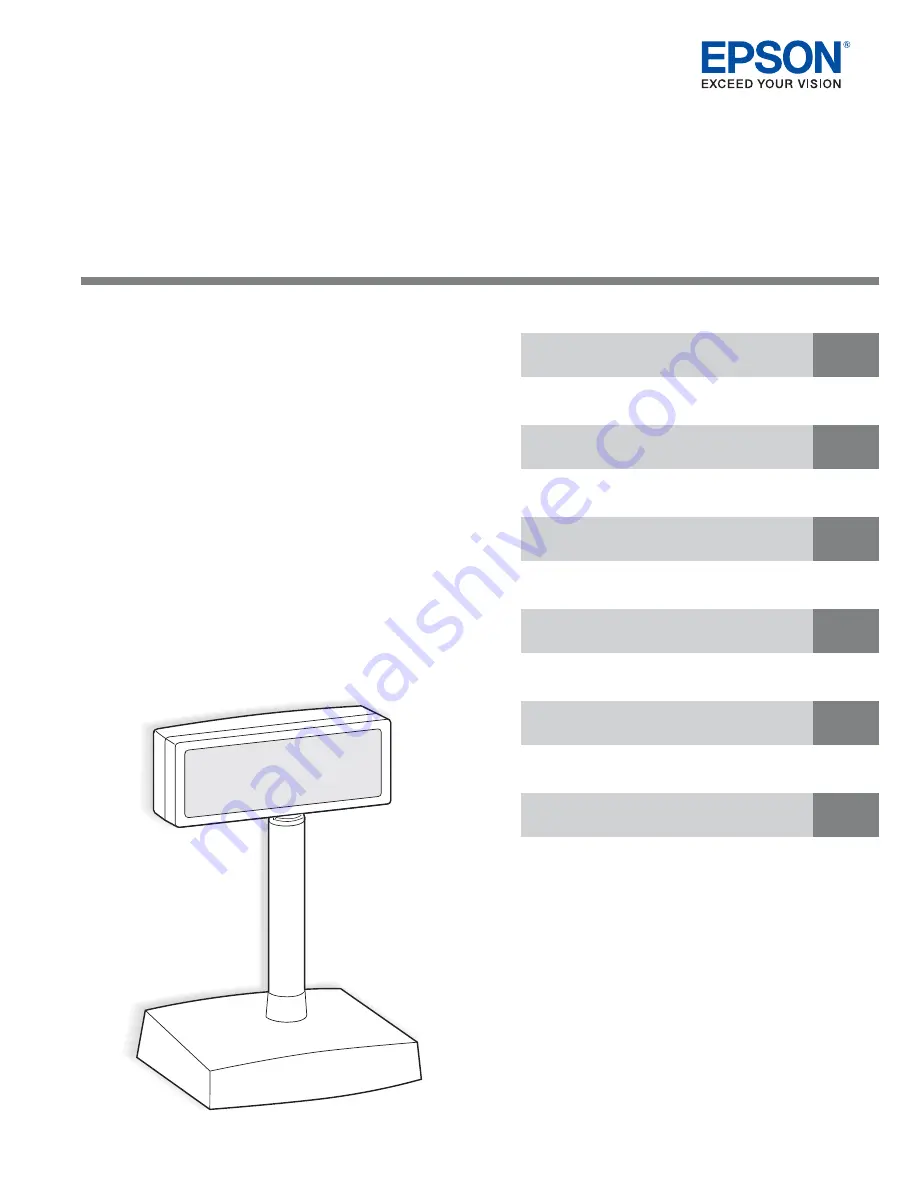
DM-D500

Technical Reference Guide

Describes features of the product.

Describes setup and installation of the product.

Describes information required to develop applications.

Describes how to handle the product.

Describes the hardware of the product.

Describes the character code tables.

M00087600

Rev. A

Product Overview

Setup

Handling

Application Development Information

Hardware

Character Code Tables

Summary of Contents for DM-D500 Series

Page 1: ...ion of the product Describes information required to develop applications Describes how to handle the product Describes the hardware of the product Describes the character code tables M00087600 Rev A Product Overview Setup Handling Application Development Information Hardware Character Code Tables ...

Page 2: ...to this product or excluding the U S failure to strictly comply with Seiko Epson Corporation s operating and maintenance instructions Seiko Epson Corporation shall not be liable against any damages or problems arising from the use of any options or any consumable products other than those designated as Original Epson Products or Epson Approved Products by Seiko Epson Corporation TRADEMARKS EPSON i...

Page 3: ...eful tips on the operation of your equipment WARNING Remove your equipment immediately if it produces smoke a strange odor or unusual noise Con tinued use may lead to fire Immediately unplug the equipment and contact your dealer or a Seiko Epson service center for advice Never attempt to repair this product yourself Improper repair work can be dangerous Never disassemble or modify this product Tam...

Page 4: ...rm stable horizontal surface The product may break or cause injury if it falls Do not place heavy objects on top of this product Never stand or lean on this product Equipment may fall or collapse causing breakage and possible injury Do not connect multiple extension struts If the device topples over there is a risk of damage or injury The horizontal rotating angle of the screen unit is limited by ...

Page 5: ...and installation of POS systems or development and design of printer applications Document Structure This document is composed of the following chapters and appendices Chapter 1 Product Overview Chapter 2 Setup Chapter 3 Application Development Information Chapter 4 Handling Appendix A Hardware Appendix B Character Code Tables ...

Page 6: ...6 ...

Page 7: ...s 13 System Configuration 14 Connection Patterns 14 Connecting a TM Printer and Option 18 Product Specifications 20 Specifications 20 Dimensional Drawing 21 Options 22 DP 501 22 DP 502 23 DP 503 25 Power Supply Unit PS 180 26 Setup 27 Flow of Setup 27 Choosing the Installation Method 28 Precautions for Installation 29 Installing the Customer Display 30 Attaching to DP 501 30 Attaching to DP 502 TM...

Page 8: ...als 55 Drivers 55 Download 56 Storing and Retrieving Graphics 57 OPOS 57 APD 57 ESC POS 57 Handling 59 Precautions for Handling 59 Turning and Tilting the Display 59 Hardware 61 Interface Signal Wiring Block Diagram 61 Data Flow 62 Stand alone Connection 62 Pass through Connection 63 Y Connection 64 Connectors 65 DM D500 Connector 65 DP 501 66 Character Code Tables 69 Character Code Tables 69 ...

Page 9: ...size is 8x16 dots Vacuum fluorescent display It allows for wide viewing angle and good legibility in both well lit and dark locations In addition the vacuum fluorescent display has a long life Avoid continuously turning on the same dot for long periods of time as it may cause luminance degradation Green display color with adjustable brightness NV memory to store and display graphics Installation W...

Page 10: ...al port of a computer Software Supported by EPSON OPOS ADK EPSON OPOS ADK for NET EPSON JavaPOS ADK and EPSON Advanced Printer Driver Ver 4 APD4 It can also be controlled with ESC POS commands For this reason it can also be used in an environment where other than the Windows OS is running Compatibility This product can replace DM D10X 20X without any changes to the application In the case of OPOS ...

Page 11: ...11 Chapter 1 Product Overview 1 Product Information Parts Name DM D500 OFF ON Connector Screen DIP switch rear side of the display Power switch underside of the display Modular cable ...

Page 12: ...ower supply connection Connector for DM D500 connection Connector for power extension cable connection Connector for computer connection serial DM D connector JP2 JP1 Connector for printer connection serial DM D500 DM D500 cable for printer connection DP 502 DM D500 ...

Page 13: ...e unit Extends the pole length of the DM D500 It is used in combination with DP 501 DP 501 DM D stand The stand used when using DM D500 as a stand alone display DP 502 DM D pole unit for TM printers The pole unit used to attach DM D500 to H6000IV U675 U950 DP 503 DM D pole unit for TM printers The pole unit used to attach DM D500 to TM H5000II PS 180 Power supply unit The power supply unit It requ...

Page 14: ...tomer s system and type of TM printer to be used simultaneously Stand alone connection Serial The stand alone connection uses one serial port of the computer for the customer display It requires the DP 501 dedicated stand PS 180 DM D500 DP 501 Computer Serial Data flow in stand alone connection Computer DM D500 Serial ...

Page 15: ...s connected to the TM printer and cash drawer via the customer display This is possible only when all equipment is connected in serial and requires the DP 501 dedicated stand TM Printer PS 180 Computer Power extension cable DM D500 DP 501 Serial Serial Computer DM D500 TM Printer DP 501 Serial Data flow in pass through connection ...

Page 16: ... when the TM printer is equipped with a DM D connector and connected using serial connection The power supply is connected to the TM printer PS 180 TM Printer DM D500 DP 502 Serial Computer TM Printer PS 180 DM D500 DP 501 Computer Serial With DP 502 With DP 501 Computer DM D500 TM Printer Serial Serial DM D500 Modular Cable Data flow in Y connection ...

Page 17: ...a connection in which the product is connected to the TM printer s USB interface with DM D connector via an RS 232 cable and the TM printer and a computer are connected via a USB cable Power is supplied from the TM printer TM Printer DM D110 DM D210 Computer USB USB I F PS 180 ...

Page 18: ...M U295 Serial Yes Yes No No Parallel Yes No No No USB Yes No No Yes Ethernet wireless LAN Yes No No No TM J2100 J2000 TM H6000IV TM U675 TM U950 TM U590 Serial Yes Yes No No Parallel Yes No No No USB Yes No No Yes TM H5000II Serial Yes Yes No No Parallel Yes No No No USB Yes No No Yes TM T285 Serial Yes Yes No No Model Interface Connection pattern Stand alone connection Pass through connection Y c...

Page 19: ... 503 DP 503 can be used with the following TM printers Model Interface Connection pattern Stand alone connection Pass through connection Y connec tion USB con trolled TM H5000II Serial No No Yes No Parallel No No No No USB No No No Yes ...

Page 20: ...ages Kanji characters JIS Level 1 and 2 GB2312 KS C5601 BIG5 Character composition device font Font A 8 x 16 dot matrix Font B 5 x 7 dot matrix Kanji 16 x 16 dot matrix Character size Font A 4 4 x 8 8 mm Font B 3 3 x 4 4 mm Kanji 8 8 x 8 8 mm Interface Standard Compliant with RS 232C Connector RJ 45 Expected product lifetime 30 000 hours Time for the luminance of the vacuum fluorescent display to ...

Page 21: ...ion 5 to 40 C Storage 10 to 50 C Humidity Operation 30 to 85 without dew condensation Storage 30 to 90 without dew condensation Weight Main unit DM D500 460 g Option DP 501 440 g Option DP 502 264 g Package contents Manual Warranty Specification overview 213 mm 83 mm 51 mm 48q DM D500 0 55 35 0 0 55 140 6 Unit mm Display Size 256 x 64 dot ...

Page 22: ...When connected to a power supply unit it can provide power to the TM printer as well Regarding specifications of the DP 501 connectors see DP 501 on page 66 Package contents Items supplied with DP 501 are as follows Dimensions Manual Fixing screws for RS 232 connector DM D stand Power extension cable 1000r20 mm 118 mm 65 mm 200 mm DP 501 Power extension cable ...

Page 23: ...02 are as follows Note that not all the items will be used depending on the connection topology Fixing plate B Support B extension Support C Fixing plate A Rubber feet small Rubber feet square Rubber feet large Stopper Fixing screw Angle fixing screw Fixing screws for rubber feet small Fixing screws for fixing plate B Fixing screws for plastic parts Hook and loop fastener set Fixing screws for met...

Page 24: ...24 Dimensions 260 mm 78 mm 164 mm DP 502 ...

Page 25: ...er Regarding TM printers to which DP 503 can be attached to see Connecting a TM Printer and Option on page 18 Package contents Items supplied with DP 503 are as follows Dimensions Tapping screws for fixing M3 10 3 pcs Installation base unit for TM Support B Support C 260 mm 50 mm 53 mm DP 503 ...

Page 26: ...ety Specification overview Electrical characteris tics Input conditions Input voltage rated AC 90 to 264 V AC 100 V 10 to AC 230 V 15 Frequency rated 50 60 Hz 3 Hz Power consumption rated 100 VA Output conditions Output voltage rated DC 24 V 5 Output current rated 2 0 A Output power rated 48 VA Peak output current 4 5 A Unit specifi cation Dimensions H x W x D 68 x 136 x 32 mm 2 68 5 35 1 26 exclu...

Page 27: ...s chapter describes the methods of installing the customer display Flow of Setup Choosing the Installation Method Installing the Customer Display Setting the Jumpers on DP 501 Checking the DM D500 Operation Setting the DIP Switches ...

Page 28: ... Chapter 1 Installing on a countertop by attaching to DP 501 Attach DM D500 to DP 501 to install on a countertop See Attaching to DP 501 on page 30 Attaching to a TM printer using DP 502 This is possible when the TM printer allows the DP 502 to be attached In this case the possible connection pat tern is limited to Y connection TM H6000 series TM U675 See Attaching to DP 502 TM H6000 series TM U67...

Page 29: ...void installing in dirty or dusty locations Avoid installing on unstable locations or in locations subject to frequent vibrations When connecting or disconnecting a cable be sure the customer display and system are turned off The DM D500 includes a vacuum fluorescent display When handling be careful not to drop or hit it When handling the product do not lift it by the modular cable Also do not pul...

Page 30: ... on the connection pattern to use For longer poles use the extension support DP 105 These are all sold separately Power supply unit PS 180 AC cable Extension support Hook and loop fasteners Extension support DP 105 DP 501 Base plate DM D stand Fixing screws for RS 232C connector Power extension cable Serial cable Two in the case of pass through connection ...

Page 31: ...screw comes with a groove or not as shown in the figure below JP1 JP2 Description 1 2 1 2 Set when connecting both the TM printer and stand for use Set in this way when using pass through connection Default 2 3 2 3 Set when using the customer display in a stand alone connection without connecting a TM printer Set in this way when using stand alone connection When connecting or disconnecting a cabl...

Page 32: ...ing the pole height of the display attach the extension support DP 105 to the display 2 Insert the display or extension support into the DP 501 Insert the display or extension support into the DP 501 all the way in until it clicks When using the extension support DP 105 ...

Page 33: ...ble to the DM D connector inside the DP 501 In the case of a Y connection connect to the DM D connector on the printer and proceed to step 9 In the case of a printer with two DM D connectors use the connector by the interface Connecting to the stand Connecting to the printer ...

Page 34: ...nd of the interface cable to the connector for printer connection inside the DP 501 and the other end to the connector on the printer Tighten the screws on both sides of the connectors 6 Connect the power extension cable If not using the power extension cable proceed to step 7 Connect one end of the power extension cable to the connector for power extension cable connection inside the DP 501 with ...

Page 35: ...to push the base plate all the way in until it is locked by the hooks on the DP 501 11When using the extension support attach hook and loop fastener to the four corners of the base plate to prevent the unit from falling down and install in the designated place 12Plug in the power supply unit to a power outlet For power supply unit use the optional PS 180 When connecting or disconnecting the DC cab...

Page 36: ...moved freely Required items The following items are used to attach DM D500 to a TM H6000 series printer or TM U675 These items are supplied with DP 502 To connect the TM printer to a computer a USB or serial cable a power supply and an AC cable are necessary Stopper Fixing screw for the stopper Angle fixing screw Fixing plate B Fixing plate A Support B extension Support C Fixing screws for rubber ...

Page 37: ...d insert the customer dis play into support C When using the extension support B insert support B into support C all the way in until it clicks 2 Attach the rubber feet to the printer When connecting or disconnecting a cable be sure the customer display and system are turned off When using support B extension ...

Page 38: ...38 3 Attach fixing plate B to the printer 4 Pass the DM D500 connection cable through the hole on fixing plate A and fix the cable to the underside of fixing plate A ...

Page 39: ...er with two DM D connectors use the connector by the interface 6 Using the stopper attach fixing plate A to the printer When attaching the stopper insert the projections of the stopper into the holes of fixing plate B The fixing plate A can be attached on either side of the printer The figure below shows when it is attached to the right ...

Page 40: ...of the following four positions Align the fixing plate A to the desired angle and secure the position using the angle fixing screw The paper roll cover of the printer may not open if the position of the display is inappropriate Before securing the position of DM D500 be sure to check that the paper roll cover of the printer can be opened Paper roll cover ...

Page 41: ...e excess cable length inside the support and insert the support into fixing plate A 9 Connect the printer power cable and fix the cable with the hook on the fixing plate B as shown in the figure below to prevent it from getting loose ...

Page 42: ...Pass the DM D500 connection cable through support C and insert the customer dis play into support C When using the extension support B insert support B into support C all the way in until it clicks When connecting or disconnecting a cable be sure the customer display and system are turned off Fixing plate A Support B extension Support C Rubber feet square Fixing screws for metal plate When using s...

Page 43: ...43 Chapter 2 Setup 2 2 Attach the rubber feet to the printer 3 Pass the DM D500 connection cable through the hole on fixing plate A and fix the cable to the underside of fixing plate A ...

Page 44: ...he DM D500 connection cable to the DM D connector on the TM printer In the case of a printer with two DM D connectors use the connector by the interface 5 Adjust the cable length and fix the fixing plate A to the printer using screws ...

Page 45: ...45 Chapter 2 Setup 2 6 Store the excess cable length inside the support and insert the support into fixing plate A ...

Page 46: ...mer display 1 Pass the DM D500 connection cable through support C and insert the customer dis play into support C When using the extension support B insert support B into support C all the way in until it clicks When connecting or disconnecting a cable be sure the customer display and system are turned off Installation base unit for TM Tapping screws for fixing M3 10 3 pcs Support B Support C When...

Page 47: ...r and secure it with the screws 3 Pass the DM D500 connection cable through the installation base unit 4 Insert the tab on the installation base unit into the hole on the support until you feel it click 5 Connect the connector of the DM D500 connection cable to the DM D connector on the TM printer ...

Page 48: ... 2 1 to ON In an USB controlled serial set the transfer speed to 19200 bps Functions that can be set with the DIP switches are as follows DIP switch 1 1 XON XOFF is valid only for stand alone connections 2 In OPOS and APD4 use the DIP switch in default setting DTR DSR Transfer speed switching DSW1 No Function ON OFF Default setting 1 1 Error Data Reception Ignore display OFF 1 2 Handshake XON XOFF...

Page 49: ...he TM printer The device selection can be changed by using the ESC POS command 4 In OPOS and APD4 use the DIP switch in default setting 5 Do not change the OFF setting Changing the DIP switch settings 1 Turn off DM D500 2 Remove the DIP switch cover DSW2 No Function ON OFF Default setting 2 1 Y Connection Setting Enabled Disabled OFF 2 2 Self test Execution 1 Yes No OFF 2 3 20 column 2 line Mode S...

Page 50: ...50 3 Change the switch position using a pointed object 4 Put the cover back 5 After changing the DIP switch settings turn on the power ...

Page 51: ...M D500 2 Set SW2 2 of DIP switch 2 to ON and turn on DM D500 3 The self test runs If the self test completes normally the display becomes ready to receive data Details of the self test In the self test the following 8 steps are executed in order 1 Turn on all display elements of the screen 2 Display a diagonal line and slide by 1 dot 3 Display the ROM version Displays the boot system and firmware ...

Page 52: ...is scrolled horizontally 7 Display brightness Displays a message by setting the brightness to 20 40 60 and 100 respectively For 1 sec ond each 8 Display the time Starts by displaying 12 34 00 at the lower right of the screen and then moves up the message by top line while scrolling horizontally ...

Page 53: ...ment cost and effective use of application assets ESC POS Commands ESC POS is the Epson original printer command system With ESC POS commands you can directly control all the TM printer functions but detailed knowledge of printer specifications or combination of commands is required compared to using a driver To use ESC POS commands you need to agree to a nondisclosure contract first and obtain th...

Page 54: ...r line Initialize display Select an international character set Select character code table Specify overwrite mode Turn cursor display mode on off Set display screen blink interval Set and display counter time Display counter time Brightness adjustment Turn reverse mode on off Execute self test Start end macro definition Execute macro ...

Page 55: ...on Manual User s Manual Application Development Guide UnifiedPOS Retail Peripheral Architecture 2 Sample Program Guide EPSON OPOS ADK for NET OPOS ADK for NET allows you to develop applications that are compatible with Microsoft POS for NET When developing applications use a separate development environment such as Microsoft Visual Studio NET Notes on using the DM D500 with Epson s OPOS Do not use...

Page 56: ...ications 2 This guide describes general information on how to control printers using the OPOS ADK in the chapter Display and Section 5 It does not describe Epson s specific functions Download Drivers and manuals can be downloaded from one of the following URLs For customers in North America go to the following web site and follow the on screen instructions http www epsonexpert com For customers in...

Page 57: ...4 dots in mind OPOS Graphics data is stored using the TMFLogo Utility bundled with OPOS The data can be retrieved from applica tions View ports in text mode cannot display graphics APD APD Ver 4 comes with a built in TMFLogo Utility The data can be retrieved from applications Text drivers cannot display graphics ESC POS Graphics can be stored directly using ESC POS command or by using the TMFLogo ...

Page 58: ...58 ...

Page 59: ...includes a vacuum fluorescent display When handling be careful not to drop or hit it Turning and Tilting the Display The display orientation and angle can be changed by moving the display while holding the support The display moves easily so do not force it any further when it stops The range of movement for the display is as indicated below The horizontal rotation angle of the display is limited ...

Page 60: ...60 ...

Page 61: ...f DM D500 and DP 501 Display Display CPU Switched by DSW2 1 Level shifter Display connector Modular 8 Connector for display connection Modular 8 TXD DSR DTR RXD DP 501 D Sub 25 female connector for host connection D Sub 9 male connector for printer connection TXD 2 DSR 6 DTR 20 RXD 3 RTS 4 RESET 25 TXD 3 DSR 6 DTR 4 RXD 2 RESET 9 Connection switched by JP1 and JP2 JP2 JP1 1 2 3 1 2 3 ...

Page 62: ...isplay to the host When 2 3 is selected in jumpers JP1 and JP2 on the DP 501 Enabled only when the display is selected by the peripheral equipment command of ESC POS for using user setting commands Settings for communication must be the same for the computer and customer display Data transmission from DM D500 to a computer is disabled default setting It is not used by the driver either To use this...

Page 63: ...r of the display and then processed sequentially to only send data for the printer to the printer Data from the printer is sent directly to the computer without passing through the display Data for the customer display and that for the printer are distinguished by the select peripheral device com mand Settings for communication must be the same for all of the computer printer and customer display ...

Page 64: ...e customer display Data for the customer display and that for the printer are distinguished by the peripheral equipment com mand of ESC POS When the printer is connected via serial the settings for communication must be the same for the computer and customer display In addition when turning on the power turn on the customer display before the printer Power supply Printer DM D500 Transmit data from...

Page 65: ...2 MARK The display is not ready to receive data The display enters the MARK status in the following cases 1 During power on initialization 2 During self test 3 When the empty capacity of the receive buffer becomes 128 bytes or less the following case applies to pass through connection only 4 When DSR enters the MARK status on printer selection SPACE The display is ready to receive data The display...

Page 66: ...ACE The host is ready to receive data MARK The host is not ready to receive data 7 GND Signal GND 20 1 DTR Output Indicates whether or not the display is ready to receive data 2 MARK The display is not ready to receive data The display enters the MARK status in the following cases 1 During power on initialization 2 During self test 3 The empty capacity of the receive buffer is 128 bytes or less 4 ...

Page 67: ...isplay printer 4 DTR Output Indicates whether or not the host is ready to receive data SPACE The host is ready to receive data MARK The host is not ready to receive data 5 GND Signal GND 6 DSR Input Indicates whether the display is ready to receive data from the printer SPACE The printer is ready to receive data Send once data is ready MARK The printer is not ready to receive data Do not send even...

Page 68: ... base of the DP 501 one for connecting the power supply unit and another for supplying power to the printer Pin assignments Pin Num ber Signal Name Signal Direction Signal Function 1 24V Power supply 2 GND Ground 3 NC Unused SHELL FG Frame ground SHELL 2 1 3 ...

Page 69: ...aracter set U S A Page 0 Indicated characters 00H 7FH Note 1 Character codes from 00H hexadecimal to 7FH hexadecimal for each page are the same Note 2 Some characters indicated by character codes from 00H to 7FH are changed by selecting the interna tional character set Refer to Section A 13 International character set for details ...

Page 70: ...70 Page 0 Indicated Characters 80H FFH ...

Page 71: ...71 Appendix B Character Code Tables Page 1 Katakana Page 1 Indicated Characters 80H FFH ...

Page 72: ...72 Page 2 PC850 Multilingual Page 2 Indicated Characters 80H FFH ...

Page 73: ...73 Appendix B Character Code Tables Page 3 PC860 Portuguese Page 3 Indicated Characters 80H FFH ...

Page 74: ...74 Page 4 PC863 Canadian French Page 4 Indicated Characters 80H FFH ...

Page 75: ...75 Appendix B Character Code Tables Page 5 PC865 Nordic Page 5 Indicated Characters 80H FFH ...

Page 76: ...76 Page 16 WPC1252 Page16 Indicated Characters 80H FFH ...

Page 77: ...77 Appendix B Character Code Tables Page 17 PC866 Cyrillic 2 Page17 Indicated Characters 80H FFH ...

Page 78: ...78 Page 18 PC852 Latin 2 Page18 Indicated Characters 80H FFH ...

Page 79: ...79 Appendix B Character Code Tables Page 19 PC858 Euro Page19 Indicated Characters 80H FFH ...

Page 80: ...80 Page 254 Space Page254 Indicated Characters 80H FFH ...

Page 81: ...81 Appendix B Character Code Tables Page 255 Space Page255 Indicated Characters 80H FFH UD undefined ...

Page 82: ...ESC POS Commands on page 53 International Character Set Indicated Character Selection by Command ASCII code Hex Country 23 24 40 5B 5C 5D 5E 60 7B 7C 7D 7E U S A France à ç é ù è Germany Ä Ö Ü ä ö ü ß U K Denmark I Æ Ø Å æ ø å Sweden É Ä Ö Å Ü é ä ö å ü Italy é ù à ò è ì Spain I Pt Ñ ñ J apan Norway É Æ Ø Å Ü é æ ø å ü Denmark II É Æ Ø Å Ü é æ ø å ü Spain II á Ñ é í ñ ó ú Latin America á Ñ é ü í ñ...

Reviews: