Epson DM-D500 Series, Installation Manual
The Epson DM-D500 Series is a high-performance customer display designed for point-of-sale applications. Ensure smooth integration with your system by referring to the user-friendly Installation Manual. Download the manual for free from our website, manualshive.com, and gain valuable insights to optimize your product usage.
Share
Download


Reviews:
No comments
Related manuals for DM-D500 Series
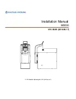
MS500
Brand: Nautilus Hyosung Pages: 23
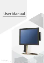
110 Series
Brand: Sam4s Pages: 106
Class 500
Brand: National Cash Register Pages: 22
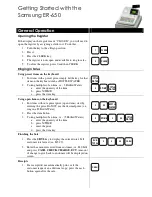
ER-650
Brand: Samsung Pages: 3
ER-290
Brand: Samsung Pages: 66
ER-265
Brand: Sam4s Pages: 106
ER-150
Brand: Samsung Pages: 2

ER-260 SERIES
Brand: Sam4s Pages: 109
ER-390 SERIES
Brand: Sam4s Pages: 206
J3500E
Brand: JCM Pages: 20

WBA Series
Brand: JCM Pages: 92

7448 Workstation
Brand: NCR Pages: 61
ECR 8100
Brand: Olivetti Pages: 70
ECR 7100
Brand: Olivetti Pages: 2

ECR 7100
Brand: Olivetti Pages: 31

ECR 7700
Brand: Olivetti Pages: 38
ECR 6900
Brand: Olivetti Pages: 50

ECR 5500
Brand: Olivetti Pages: 67


