
D e v e l o p e r ’ s G u i d e
M00107502
Rev.C
Functions and Operating
Procedures of the Printer
Application Development
Information
Series
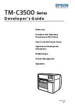
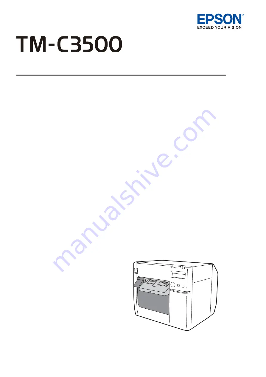
The Epson C31CD54011 is a versatile and high-performance printer that ensures efficient and reliable operations. Enhance your printing experience with this exceptional product by referring to the comprehensive "Developer's Manual". Download this manual for free from our website to explore all the features and optimize your printer's performance.
D e v e l o p e r ’ s G u i d e
M00107502
Rev.C
Functions and Operating
Procedures of the Printer
Application Development
Information
Series