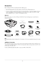
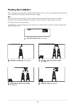
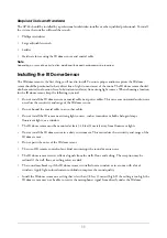
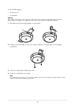
Epson AP-60 - Projector Sound Solution, Installation Manual
The Epson AP-60 - Projector Sound Solution offers a seamless audio experience for your projector setup. Enhance your presentations and movie nights with this compact and versatile sound solution. For convenient troubleshooting and setup assistance, download the comprehensive user manual for free from our website manualshive.com.
Share
Download

Reviews:
No comments
Related manuals for AP-60 - Projector Sound Solution
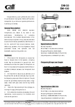
DM-50
Brand: GATT AUDIO Pages: 2
ICON
Brand: Earthworks Audio Pages: 3

LM10
Brand: Samson Pages: 24
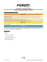
FUSION
Brand: Garmin Pages: 8
GP3
Brand: IASUS Pages: 2
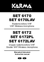
6170
Brand: Karma Pages: 12
AG-MC15P
Brand: Panasonic Pages: 12
WV-SMR10
Brand: Panasonic Pages: 20
Q1
Brand: Samson Pages: 4
P30
Brand: Earthworks Pages: 2
TC25
Brand: Earthworks Pages: 2
SMART
Brand: Hama Pages: 78
Net Mic
Brand: 2N Pages: 4
BM100
Brand: Uniden Pages: 2
CM 100
Brand: Nady Systems Pages: 2
B1000
Brand: C-ducer Pages: 4
E-200
Brand: CAD Pages: 4
DM-20
Brand: Hama Pages: 38


