background image

EPSON Stylus COLOR 900/900N

Color ink jet printer 

TM-SC900/N

®

6(59,&(0$18$/

Summary of Contents for 900N

Page 1: ...EPSONStylusCOLOR900 900N Color ink jet printer TM SC900 N 6 59 0 18 ...

Page 2: ...unique features of this product and explains the operation of its main electrical and mechanical systems CHAPTER 3 TROUBLESHOOTING Provides step by step procedures for troubleshooting CHAPTER 4 DISASSEMBLY AND ASSEMBLY Provides step by step procedures for disassembling and assembling the product CHAPTER 5 ADJUSTMENTS Describes Epson approved methods for adjustment CHAPTER 6 MAINTENANCE Describes r...

Page 3: ...ges losses costs or expenses incurred by purchaser or third parties as a result of accident misuse or abuse of this product or unauthorized modifications repairs or alterations to this product Epson America Inc shall not be liable against any damages or problems arising from the use of any options or any consumable products other than those designated as Original EPSON Products or EPSON Approved P...

Page 4: ...he receiving antenna Increase the separation between the equipment and receiver Connect the equipment into an outlet on a circuit different from that to which the receiver is connected Consult the dealer or an experienced radio TV technician for help WARNING The connection of a non shielded equipment interface cable to this equipment will invalidate the FCC Certification of this device and may cau...

Page 5: ...ect the unit to a power source until instructed to do so When the power supply cable must be connected use extreme caution in working on the power supply and other electronic components CAUTION 1 Repairs on EPSON products should be perfomed only by an EPSON certified repair technician 2 Make certain that the source voltage is the same as the rated voltage listed on the serial number rating plate I...

Page 6: ...ace Selection 23 Control Panel Operation 25 Indicators LEDs 25 Panel Functions 26 Printer Condition and Panel Status 29 Error Status 30 Ink Out 30 Paper Out 30 Paper Jam 30 No Ink Cartridge 30 Maintenance Request 30 Fatal Errors 30 Printer Initialization 31 Chapter 2 Operating Principles Overview 33 Printer Mechanism Operating Principles 34 Carriage Mechanism 34 Printhead Operation 35 Pump ASF Mot...

Page 7: ...omputer 121 Starting the Adjustment Program 122 Market Destination Check 125 Printhead ID Input 127 Printhead Angular Adjustment 130 Bi Directional Adjustment 138 Cleaning the Printhead 143 Initial Ink Charge 145 Checking and Clearing the Waste Ink Counter 146 Fan Check 149 Platen Gap Parallelism Adjustment 150 Adjusting the Platen Gap 150 Checking the Platen Gap 152 Chapter 6 Maintenance Overview...

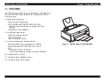
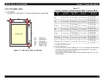
Page 8: ... 37 5 PRODUCTDESCRIPTION ...

Page 9: ...weave printing to eliminate banding Improvement in color rendering A built in auto sheet feeder Holds 100 cut sheets 64 g m2 Holds 10 envelopes Holds 30 transparency films 3 built in interfaces and 1 interface card slot Macintosh serial I F up to approximately 1 8 Mbps Bi directional parallel I F lEEE 1284 level 1 device USB Optional Type B level 2 I F card slot 10 100 Type B Ethernet interface in...

Page 10: ...C P2 and expanded raster graphics code EPSON Remote command IBM X24E emulation Table 1 1 Print Speed and Printable Columns for Character Mode Character pitch Printable columns LQ speed 10 CPI Pica 80 285 CPS 12 CPI Elite 96 342 CPS 15 CPI 120 428 CPS 17 CPI Pica condensed 137 487 CPS 20 CPI EIite condensed 160 570 CPS Table 1 2 Print Speed and Printable columns for Raster Graphics Mode Horizontal ...

Page 11: ...Bit map LQ fonts EPSON Roman 10 cpi 12 cpi 15 cpi proportional EPSON Sans Serif 10 cpi 12 cpi 15 cpi proportional EPSON Courier 10 cpi 12 cpi 15 cpi EPSON Prestige 10 cpi 12 cpi 15 cpi EPSON Script 10 cpi 12 cpi 15 cpi Scalable fonts EPSON Roman 10 5 pt 8 pt 32 pt 2 pt increments EPSON Sans Serif 10 5 pt 8 pt 32 pt 2 pt increments EPSON Roman T 10 5 pt 8 pt 32 pt 2 pt increments EPSON Sans Serif H...

Page 12: ...N Sans Serif EPSON Roman T EPSON Sans Serif H NLSP version Italic table PC 850 Multilingual PC 861 Icelandic Abicomp lSO Latin 1 ISO 8859 15 PC 437 US Standard Europe PC 860 Portuguese PC 865 Nordic BRASCIl Roman 8 PC 858 PC437Greek PC 853 Turkish PC 857 Turkish PC 869 Greek Code MJK CSFR lSO Latin 1T Turkish PC7 74 1SO 8859 2 lSO Latin 2 PC 866 UKR PC 852 East Europe PC 855 Cyrillic PC 866 Russia...

Page 13: ...in computer to D SUB 25 pin printer C83605 C83606 USB Interface Cable shielded from Series A 4 pin computer to Series B 4 pin printer This cable is not supplied in all locations C83623 Items Codes Black Ink Cartridge T003011 Color Ink Cartridge T005011 Items Codes EPSON 360 dpi Ink Jet Paper A4 S041059 EPSON 360 dpi Ink Jet Paper Letter S041060 EPSON Photo Quality Ink Jet Paper A4 S041061 EPSON Ph...

Page 14: ...ght 17 Ib 64g m2 24 Ib 90g m2 Paper Types Bond paper Plain paper EPSON special media 1 2 3 2 Transparencies Glossy Paper Size A4 Width 8 3 210 mm x Length 11 7 297 mm Letter Width 8 5 216 mm x Length 11 0 279 mm A6 Width 4 1 105 mm x Length 5 8 148 mm Thickness 0 003 0 075 mm 0 0033 0 085 mm Paper Types EPSON special media NOTE Print transparencies at normal temperatures only 1 2 3 3 Envelope Thic...

Page 15: ... 1 2 3 5 Self Adhesive Sheets Size A4 Width 8 3 210 mm x Length 11 7 297 mm Paper Types EPSON special media 1 2 3 6 Photo Paper Size A4 Width 8 3 210 mm x Length 11 7 297 mm Letter Width 8 5 216 mm x Length 11 0 279 mm 4 x 6 Width 4 102 mm x Length 6 152 mm Panoramic Width 8 3 210 mm x Length 23 4 594 mm Paper Types EPSON special media 1 2 3 7 Photo Stickers Size A6 16 frames Width 4 1 105 mm x Le...

Page 16: ...f 0 12 3 mm is not guaranteed P r i n t a b l e a r e a B M P L T M R M P W L M L M L e f t M a r g i n R M R i g h t M a r g i n T M T o p M a r g i n B M B o t t o m M a r g i n P W P a p e r W i d t h P L P a p e r L e n g t h Paper Size Left Margin Minimum Right Margin Minimum Top Margin Minimum Bottom Margin Minimum A4 0 12 3 mm 0 12 3 mm 0 12 3 mm 0 54 14 mm 0 12 3 mm 3 A5 0 12 3 mm 0 12 3 m...

Page 17: ...Margins for Envelopes Figure 1 3 Printable Area for Envelopes Paper Size Left Margin Minimum Right Margin Minimum Top Margin Minimum Bottom Margin Minimum 10 0 12 3 mm 1 10 28 mm 0 12 3 mm 0 54 14 mm DL 0 12 3 mm 0 28 7 mm 0 12 3 mm 0 54 14 mm C6 0 12 3 mm 0 12 3 mm 0 12 3 mm 0 54 14 mm 5 x 8 0 12 3 mm 0 28 7 mm 0 12 3 mm 0 54 14 mm R M L M P r i n t a b l e A r e a B M T M ...

Page 18: ...approximately 3 hours at 77 F 25 C 1 2 5 1 Black Ink Cartridge Type Exclusive ink cartridge Color Black Print Capacity 1200 pages A4 ISO IEC 10561 Letter pattern at 360 dpi Ink life 2 years from indicated production date Storage temperature Storage 4 104 F 20 40 C within a month at 104 F 40 C Packing storage 22 104 F 30 40 C within a month at 104 F 40 C Transit 22 140 F 30 C 60 C within 120 hours ...

Page 19: ...tion date Storage temperature Storage 4 104 F 20 40 C within a month at 104 F 40 C Packing storage 22 104 F 30 40 C within a month at 104 F 40 C Transit 22 140 F 30 C 60 C within 120 hours at 140 F 60 C and within a month at 104 F 40 C Dimensions 2 1 W x 2 7 D x 1 6 H 54 0 mm x 67 4 mm x 41 8 mm Figure 1 5 Color Ink Cartridge 2 1 i n 5 4 m m 2 7 i n 6 7 4 m m 1 6 i n 4 1 8 m m 2 6 i n 6 5 9 m m r ...

Page 20: ... VAC Rated frequency range 50 60 Hz Input frequency range 49 5 60 5 Hz Rated current 0 2 A Maximum 0 3 A Power consumption Approximately 18 W ISO IEC 10561 Letter pattern ENERGY STAR compliant Insulation Resistance 10M ohms min between AC line and chassis 500 VDC Dielectric strength 1500 VAC rms 1 minute between AC line and chassis 1 2 7 Environmental Conditions Temperature Operating 50 to 95 F 10...

Page 21: ...5 subpart B class B CSA C108 8 class B 220 240 V Version Safety standard EN 60950 VDE EMI EN55022 CISPR Pub 22 class B AS NZS 3548 class B 1 2 10 Acoustic Noise Level Approximately 47 dB A According to ISO 7779 1 2 11 CE Marking 220 240 V version Low Voltage Directive 73 23 EEC EN60950 EMC Directive 89 336 EEC EN55022 Class B EN61000 3 2 EN61000 3 3 EN50082 1 IEC801 2 IEC801 3 IEC801 4 1 2 12 Phys...

Page 22: ...ore setting either ERROR LOW or PE HIGH and held HIGH until all these signals return to an inactive state The BUSY signal is HIGH During data entry see Data transmission timing When the input data buffer is full While the INIT signal is LOW or during hardware initialization During a printer error condition See ERROR signal When the parallel interface is not selected The ERROR signal is LOW when on...

Page 23: ...vel is considered HIGH at 3 0 volts or more and LOW at 2 0 V or less The receiver shall provide an impedance equivalent to 7 5K ohm to ground Table 1 13 shows the connector pin assignments and signals for the forward channel of the parallel interface Table 1 9 Data Transmission Timing Parameter Minimum Maximum tsetup 500 ns thold 500 ns tstb 500 ns tready 0 tbusy 500 ns tt out 120 ns tt in 200 ns ...

Page 24: ...DATA4 24 7 DATA5 25 8 DATA6 26 9 DATA7 27 10 ACKNLG 28 O This signal is a negative pulse indicating that the printer can again accept data 11 BUSY 29 O A HIGH signal indicates that the printer cannot receive data 12 PE 28 O A HIGH signal indicates paper out error 13 SLCT 28 O Always HIGH when the printer is on 14 AFXT 30 I Not used 31 INIT 30 I The falling edge of a negative pulse or a LOW signal ...

Page 25: ...sibility request values are 00H or 04H which means 00H Request Nibble Mode Reverse Channel Transfer 04H Request device ID using Nibble Mode Rev Channel Transfer Device ID The printer sends one of the following device ID strings upon request When IEEE1284 4 is enabled 00H 60H MFG EPSON CMD ESCPL2 PRPXL BDC D4 MDL Stylus SP COLOR SP 900 CLS PRINTER DES EPSON SP Stylus SP COLOR SP 900 When IEEE1284 4...

Page 26: ...k signal 11 PtrBusy Data Bit 3 7 29 O Printer busy signal and reverse channel transfer data bit 3 or 7 12 AckData Req DataBit 2 6 28 O Acknowledge data request signal and reverse channel transfer data bit 2 or 6 13 Xflag DataBit 1 5 28 O X flag signal and reverse channel transfer data bit 1 or 5 14 HostBusy 30 I Host busy signal 31 INIT 30 I Not used 32 DataAvail DataBit 0 4 29 O Data available si...

Page 27: ...le Apple System Peripheral 8 Cable Connector pin assignment and signal See Table 1 15 Table 1 15 Pin Assignment X ON X OFF DTR protocol See Table 1 16 Table 1 16 X On X Off and DTR Protocol Pin No Signal Name I O Description 1 SCLK O Synchronous clock signal 2 CTS I Clear To Send 3 TXD O Transmit Data 4 SG I Signal Ground 5 RXD I Receive Data 6 TXD O Balanced Transmit Data 7 DTR O Data Terminal Re...

Page 28: ... when the input buffer is full 1 3 7 Automatic Interface Selection The EPSON Stylus COLOR 900 900N has four types of interfaces USB parallel Macintosh serial and optional Type B The EPSON Stylus COLOR 900N has a 10 100 Type B Ethernet interface card Each interface is selected manually or automatically Manual Selection One of four interfaces can be selected in the default setting mode Automatic Sel...

Page 29: ...e is not effective when that interface is not selected 1 3 7 1 IEEE 1284 4 Protocol The packet protocol described by the IEEE1284 4 standard allows a device to carry on multiple simultaneous exchanges containing data and or control information with another device across a single point to point link The protocol is not however a device control language It provides basic transport level flow control...

Page 30: ...AC power is supplied 2 Paper out Comes on when the printer is out of paper and blinks when there is a paper jam 3 Ink Out Black Comes on when the printer is out of black ink and blinks when the printer is low on black ink 4 Ink Out Color Comes on when the printer is out of color ink and blinks when the printer is low on color ink P o w e r L E D P o w e r B u t t o n L o a d E j e c t B u t t o n ...

Page 31: ...es are installed Load Eject held for 2 seconds 1 Starts the I C replacement sequence even if the I Cs are full 2 Cleaning held for 2 seconds 1 Starts the printhead cleaning sequence Starts the I C replacement sequence when the printer is in one of the following conditions Ink Low Ink Out No Ink Cartridge 2 Cleaning pushed briefly When the carriage is in the black I C replacement position advances ...

Page 32: ...ult Setting Menu continued Underlined values are the defaults for the EEPROM reset Font Roman Sans Serif Courier Prestige Script Roman T Sans Serif H Draft Pitch 10 cpi 12 cpi 15 cpi 17 cpi 20 cpi Proportional Print direction Auto Bi D Uni D Loading Position 3 mm 8 5 mm Others I F mode Auto Parallel Serial USB Optional Auto I F wait mode 10 seconds 30 seconds Network I F mode network enviroments o...

Page 33: ...all the test patterns are properly aligned 8 Turn the printer off 1 4 2 2 Special Setting Mode While turning the printer on press both the Load Eject and Cleaning buttons to start the special setting mode While the Paper Out LED is blinking activate each function by pressing the appropriate button s as described in Table 1 23 Table 1 23 Special Setting Mode NOTE If you initialize the EEPROM the Bi...

Page 34: ...Indicator Status Printer Status Indicators Priority Power Ink Out Black Ink Out CMY Paper Out Power on condition On 9 Ink Sequence mode Blink 6 I C replacement mode Blink 5 Data processing Blink 8 Paper Out On 4 Paper Jam Off Off Blink 3 No I C Ink Out Black On 7 Ink level low Black Blink 7 No I C Ink Out CMY On 7 Ink level low CMY Blink 7 Enters the EEPROM and Timer IC Reset ON for 1 second only ...

Page 35: ...stalling used cartridges not fully filled with ink upsets the ink level detection and may cause serious problems in the printheads 1 5 2 Paper Out When the printer fails to load a sheet of paper it goes into the Paper Out error condition 1 5 3 Paper Jam When the printer fails to eject a sheet of paper it goes into the Paper Jam error condition 1 5 4 No Ink Cartridge When the printer detects that a...

Page 36: ...ut data buffer c Clears the print buffer d Sets the default values Operator Initialization This printer is initialized when it is turned on again within 10 seconds after it is powered off or receives an INIT signal negative pulse from the parallel interface When printer the is initialized it does the following a Caps the printhead b Ejects any paper c Clears the input data buffer d Clears the prin...

Page 37: ... 37 5 OPERATINGPRINCIPLES ...

Page 38: ...thead and printhead driver circuitry Eight separate sensors monitor the temperature at critical locations Should they detect excess heat the printer can compensate by activating a cooling fan slowing its printing speed flushing ink through the nozzles or shutting itself down See Section 2 2 2 3 and Section 2 3 9 Mechanical Features Unlike previous models the paper feed motor of the EPSON Stylus CO...

Page 39: ...2 Linear Encoder The EPSON Stylus COLOR 900 900N uses a linear encoder to obtain even carriage movement and accurate print timing The linear encoder reads bands on the encoder belt and IC2 interprets the signals from the encoder This enables the printer to produce the appropriate printhead drive frequency and to control the carriage Table 2 2 gives the linear encoder specifications Table 2 2 Linea...

Page 40: ...s basic features and operation are described below 2 2 2 1 Nozzle Configuration The printhead includes 480 nozzles divided into five rows of 96 nozzles each As shown in the figure below the black nozzles are vertically spaced at 360 dpi and the color nozzles at 180 dpi In color printing only row B among the two black nozzle rows is used Figure 2 1 Nozzle Configuration No Item Specifications 1 Moto...

Page 41: ...f each nozzle row If the temperature rises above 100 C which occurs when about half the nozzles in any row are blocked the printer automatically enters the CL2 cleaning mode the most powerful cleaning cycle This unclogs blocked nozzles and restores ink flow to cool the printhead If the cleaning cycle fails to reduce the temperature below 100 C the printer assumes that many nozzles remain clogged I...

Page 42: ...se the planetary gear set would rotate downward if unchecked To keep the gears engaged the solenoid latch holds them in place When the pump mechanism needs to be driven the motor turns counterclockwise and the solenoid is momentarily activated letting the planetary gear set swing downward and engage the pump transmission gear After the gears engage the solenoid latch holds the planetary gear set i...

Page 43: ...rotation properly The sensor s drive voltage is 5 0 V 5 and its output signal specifications are as shown below Table 2 6 ASF Sensor Output Signal Motor direction ASF gear engaged Pump gear engaged Normal rotation CW Connecting the planetary gear set to the ASF unit Reverse rotation of the paper loading roller for returning paper to the hopper Normal rotation of the pump absorption Releases the CR...

Page 44: ...f them pumps ink at a time depending on which direction the ASF pump motor is turning Figure 2 6 Pump Mechanism C l u t c h S p a c e r C o m p r e s s i o n s p r i n g C l e a n e r h e a d F r a m e U n l o c k e d L o c k e d O n t h e s a m e s h a f t I n t h e p u m p g e a r t r a i n c o n d i t i o n P u m p i n t e r m i t t e n t g e a r P u m p t r a n s m i s s i o n g e a r P r e s ...

Page 45: ... paper loading it checks if the leading edge of the paper has been correctly loaded It detects the end of the paper after printing to initiate the paper eject operation The drive voltage for the PE sensor is 5 0 V 5 and its output signal specifications are as shown below Table 2 8 PE Sensor Switch Mode No Items Specifications 1 Type 4 phase 200 pole HB type stepping motor 2 Drive voltage 42 VDC 5 ...

Page 46: ...ff Once it s deactivated it cannot recover until you turn the printer off and then back on The power supply circuit also includes a voltage drop delay circuit When you turn off the printer by pressing the external power button the delay circuit keeps the power supply on long enough for the printer to complete its power off operations paper ejection and printhead capping After a pre determined leng...

Page 47: ...c t i o n H i g h e r h a r m o n i c s a b s o r p t i o n S m o o t h i n g F u l l w a v e r e c t i f i c a t i o n I n r u s h c u r r e n t t e m p e r a t u r e c o n v e r s i o n S t a r t i n g r e s i s t o r H i g h e r h a r m o n i c s a b s o r p t i o n S m o o t h i n g 5 V l i n e o v e r v o l t a g e p r o t e c t i o n S m o o t h i n g 4 2 V l i n e c o n s t a n t v o l t a ...

Page 48: ... Figure 2 11 C265 Relay Board L E D 3 L E D 2 L E D 1 L E D 0 S W 2 S W 1 S W 0 C N 1 1 1 2 M C M C C R H P E A S F R E D W H T B L K M C C a r r i a g e h o m e p o s i t i o n C R H P s e n s o r C a r r i a g e C R m o t o r P u m p A S F m o t o r P a p e r F e e d P F m o t o r C o n n e c t o r t o C N 1 1 o n t h e C 2 6 5 M a i n B o a r d C o n n e c t o r t o C N 1 2 o n t h e C 2 6 5 M ...

Page 49: ...C265 Main board It has a 128 KB internal flash memory Since the CPU runs at 24 MHz it can send print data efficiently for high throughput The C265 main board has two independent EPSON designed ASICs ASIC1 and ASIC2 ASIC1 controls all interfaces except for the USB I F and sensors ASIC2 controls the printhead motors linear encoder and USB I F IC8 contains both the power off timer and EERPOM in one c...

Page 50: ...1 C N 1 0 C N 5 C N 6 C N 1 5 C N 1 3 T h e r m i s t o r d e t e c t s t e m p e r a t u r e o f t h e h e a t s i n k C h a r g i n g d i s c h a r g i n g d r i v e r f o r d r i v i n g t h e b l a c k n o z z l e s Q 5 u p p e r Q 6 l o w e r C h a r g i n g d i s c h a r g i n g d r i v e r f o r d r i v i n g t h e c o l o r n o z z l e s Q 3 u p p e r Q 4 l o w e r H e a t S i n k T h e r ...

Page 51: ...I C 1 2 Q 9 Q 7 C N 1 3 F A N C N 1 6 A S F S o l e n o i d C N 8 H e a d 1 C N 9 H e a d 2 C N 1 2 A S F m o t o r C N 1 0 P F m o t o r C N 1 1 C R m o t o r S N 7 5 L B C I C 1 0 7 4 L V 1 6 1 2 8 4 I C 9 P R O M I C 4 D R A M I C 5 M R A M I C 6 E 0 5 B 6 0 I C 3 E 0 5 B 5 9 I C 2 H D 6 4 F 2 3 5 7 I C 1 C N 1 C e n t r o n i c s C N 3 M a c S e r i a l C N 2 T y p e B I F C N 1 5 S e n s o r ...

Page 52: ...t power on Power is supplied by an external button cell battery a lithium battery This IC also produces the reset signals for all the major ICs such as the CPU ASIC1 ASIC 2 and motor drive ICs The head driver ICs CXA2128 x 2 IC15 and IC16 produce their own reset signals when detecting abnormal voltage so the printhead can stop in the proper sequence Component Functions Motor driver IC LB1847 IC11 ...

Page 53: ... to perform a cleaning cycle at the next power on and if so which type of cleaning to perform While the printer is on it supplies 5 V at pin 7 to operate the internal timer circuit however when the printer is off a 3 volt lithium cell battery powers the timer circuit through pin 8 Figure 2 14 Power Off Timer Reset Circuit 4 2 V S p e e d u p d i o d e 5 V R 1 8 1 0 7 K R 2 0 1 0 K B A T 1 V I N V ...

Page 54: ...e nozzle selector inside the printhead Their functions are explained on the following page Figure 2 15 Temperature Sensor Support Circuitry A N O D E 5 C N 8 C N 9 T h e r m i s t o r N o z z l e S e l e c t o r 4 H D 6 4 F 2 3 5 7 I C 1 T h e r m i s t o r o n t h e h e a t s i n k o n t h e m a i n b o a r d T h e r m i s t o r o n t h e m a i n b o a r d A N 7 A N 6 A N 5 A N 4 A N 3 A N 2 A N ...

Page 55: ...ugh its AN6 port from a thermistor mounted directly on the heat sink This lets the CPU control the cooling fan s operation AN5 Pin 110 This port receives temperature signals from a thermistor built into the printhead Based on these signals the printer makes subtle changes in the voltage level of the head drive trapezoidal waveform enabling the printer to eject the correct amount of ink at any temp...

Page 56: ...gure 2 16 Printer Mechanism Sensor Support Circuitry C N 9 2 0 2 1 C O B C O C 5 C N 8 2 1 2 0 L S 1 L S 2 E 0 5 B 5 9 I C 2 1 0 9 1 1 0 C O B C O C 9 3 9 4 E N C B E N C A 5 E 0 5 B 6 0 I C 3 S W C 0 S W A 1 S W A 0 1 3 7 1 3 6 1 3 5 5 5 3 3 P S C C N 1 5 H P P E A S F 1 6 1 5 1 4 4 C N 5 P S C 4 5 Ink Cartridge Sensors CR Home Position Sensor Paper End Sensor Power Control Signal PSC Linear Enco...

Page 57: ...culates the carriage position during printing PE Paper End Sensor The PE sensor detects the following conditions Whether paper is in the paper path at power on Whether the ASF has loaded paper properly after the printer receives a paper feed command Whether the printer has properly ejected a page after rotating the PF Paper Feed motor the predefined distance ASF Sensor In order to load paper prope...

Page 58: ... 9 8 1 4 2 8 1 5 2 5 2 4 2 3 2 2 1 8 1 9 2 0 2 1 2 7 1 6 2 6 1 7 2 1 3 3 1 2 1 4 7 1 4 8 1 4 9 1 5 0 1 6 3 1 6 2 1 6 1 1 6 0 1 4 3 1 7 0 1 4 4 1 6 9 1 7 1 1 7 2 L B 1 8 4 7 I C 1 2 1 5 1 7 3 1 7 4 1 7 5 N C M 6 2 3 8 3 I C 1 7 1 0 C R I A 0 C R I A 1 C R I A 2 C R I A 3 C R I B 0 C R I B 1 C R I B 2 C R I B 3 C R P H A A C R P H A B C R E N B A C R E N B B C R C T L 0 C R C T L 1 C R C T L 2 C R C...

Page 59: ...st feed Slow feed 1 11520 0 004 mm 5 4 2 4 2 4 2 4 2 C N 1 0 1 3 2 4 D A x x 3 E 0 5 B 5 9 I C 2 7 6 9 8 1 4 2 8 1 5 2 5 2 4 2 3 2 2 1 8 1 9 2 0 2 1 2 7 1 6 2 6 1 7 2 1 3 1 4 0 1 3 9 1 3 8 1 3 7 1 3 3 1 3 4 1 3 5 1 3 6 1 4 2 1 2 8 1 4 1 1 2 9 1 2 4 1 2 7 L B 1 8 4 7 I C 1 1 1 2 5 1 2 6 1 2 3 N C M 6 2 3 8 3 I C 1 7 4 2 P F I A 0 P F I A 1 P F I A 2 P F I A 3 P F I B 0 P F I B 1 P F I B 2 P F I B 3...

Page 60: ... 2 4 A 3 9 5 7 I C 1 3 1 5 2 2 A 3 9 5 7 I C 1 4 1 5 2 2 R E F R E F M 6 2 3 8 3 I C 1 7 D A x y 4 2 0 1 3 1 1 8 1 0 2 0 1 3 1 1 8 1 0 E 0 5 B 5 9 I C 2 6 9 6 8 6 2 6 4 6 3 8 1 8 0 7 2 7 4 7 3 A S F I A 0 A S F I A 1 A S F I A 2 A S F I A 3 A S F P H A A A S F I B 0 A S F I B 1 A S F I B 2 A S F I B 3 A S F P H A B A S F A A S F A A S F B A S F B P h a s e A s p e c i f i e d s i g n a l P h a s e...

Page 61: ...e nozzle selector is located in the printhead See Figure 2 20 for the block diagram showing the printhead driver components located on the main board The pre driver ICs CXA2128 IC15 and 16 produce the trapezoid waveform and transistors Q3 Q6 amplify it Unlike previous products serial data is transferred to each nozzle row independently to reduce the data latch time required to form one dot Excitat...

Page 62: ... R H W S D A T A H W S L C H W S L A T A 0 A 1 A 2 A 3 C L K 1 C L K 2 F L O O R D A T A D C L K E V C C 4 5 V C C 4 5 _ 2 N P N B F B P N P B C h a r g i n g d i s c h a r g i n g c i r c u i t f o r c o l o r n o z z l e s B l a c k n o z z l e r o w s C o l o r n o z z l e r o w s H e a d t e m p e r a t u r e d e t e c t i o n c i r c u i t A N d a t a t e m p e r a t u r e d e t e c t i o n f...

Page 63: ...elies on input from two thermistors t1 and t2 in Figure 2 22 Thermistor t1 is attached directly to the heat sink while t2 is located on the main board between the printhead pre driver ICs The table below shows the detected temperature and the corresponding fan operation Table 2 15 Detected Temperature and Cooling Fan Operation IC1 processes the temperature detected by the thermistors every two sec...

Page 64: ... 5 1 on page 119 or the printer may go into the Error 2 state described above and display the Ink Out error even after you install new ink cartridges The error occurs because the printhead s nozzle selector ICs are manufactured by two different vendors Sharp and EPSON Their temperature feedback circuits are slightly different When you install a new printhead it may conflict with the current printh...

Page 65: ...gram The output signal from IC2 and its effect on the solenoid are shown in the table below Table 2 17 Conditions for Driving the ASF Solenoid The solenoid s specifcations are included below Table 2 18 ASF Solenoid Specifications IC2 output pin 83 Solenoid s operation High 5 VDC On Low 0 VDC Off C N 1 6 G N D 2 1 V B B 4 2 F 4 E 0 5 B 5 9 I C 2 A S F _ S O L 8 3 Q 9 Q 8 C o o l i n g f a n Item Sp...

Page 66: ... controls various adjustment values total ink consumption and current ink consumption for each color When the printer is turned off the data and adjustment values accumulated in the D RAM are written back to the EEPROM under the ASIC s control Information is transmitted between the ASIC IC3 and the EEPROM in serial data format Figure 2 24 EEPROM Control Circuit Block Diagram A d d r e s s D a t a ...

Page 67: ... 37 5 TROUBLESHOOTING ...

Page 68: ...or see Troubleshooting with LED Error Indicators on page 66 Checking for other hardware problems If you suspect a problem with one of the motors or you get an Ink Out error after installing new ink cartridges see Checking for Other Hardware Problems on page 78 Print Quality Troubleshooting If you notice problems with the print quality such as missing dots or lines misaligned vertical lines or band...

Page 69: ...ce Error Blinking Blinking Blinking Blinking Fatal Error Blinking On On Blinking Error Condition Possible Causes Paper Out Error Refer to Section 3 1 1 1 1 Failure in paper feeding 2 Connector for the PE sensor is disconnected 3 The PE sensor actuator is working improperly The sensor base is not attached properly 4 The PE sensor is defective 5 ASF is damaged Paper Jam Error Refer to Section 3 1 1 ...

Page 70: ...green 4 pin connector is irrelevant it is for the encoder 5 The I C sensor micro switch is defective 6 The value of the ink consumption counter in the EEPROM is corrupted 7 Ink cartridge replace command is generated because an abnormal temperature is detected Maintenance Error Refer to Section 3 1 1 4 The waste ink pads need to be replaced After replacing the pads you must clear the error Fatal Er...

Page 71: ...e spring Referring to the illustration above check that the sensor base is securely installed to the frame If the sensor base is loose install it securely C L S h e e t N o n a d h e s i v e A r e a A d h e s i v e A r e a T h i s s i d e d o w n U s e a p o s t c a r d f o r t h e b a s e s h e e t S t a p l e r s C l o t h m o i s t e n e d w i t h a l c o h o l Staples B o t t o m v i e w o f t...

Page 72: ...is beyond the specifications 2 Is the encoder sensor located at the back of the CR covered with dust Check if there is any dust or paper debris lodged in the encoder sensor a photo sensor located at the back of the carriage 3 Is the encoder belt nearly dislocated from the encoder Referring to the illustration above make sure the encoder belt passed throught the slot in the encoder sensor 4 Is the ...

Page 73: ...ts for proper connection and electrical continuity since checking the signal directly from the encoder is impossible 1 Is Connector 1 secure 2 Is Connector 2 secure 3 Is there electrical continuity through the cable C a r r i a g e v i e w e d f r o m t h e b a c k H e a d s u r f a c e C o n n e c t o r 1 C h e c k f o r c o n t i n u i t y C o n n e c t o r 2 Step Problem Solution 8 Is the ASF i...

Page 74: ...ad cleaning Color and black ink are tracked separately The counter is normally reset its value returned to zero when the I C replacement sequence is performed However if the user attempts to replace ink cartridges without following the correct replacement procedure the printer may stop printing and display the Ink Out error even though plenty of ink remains in the cartridges Install new ink cartri...

Page 75: ...ep Problem Solution 6 Is data in the EEPROM corrupted If the address for the ink consumption information in the EEPROM is corrupted and the printer shows the Ink Out error constantly the printer sets the interface signal BUSY to High and stops communication with any other peripheral devices Therefore replace the ink cartridges with new ones to overwrite the address with 00H 7 Did you replace the p...

Page 76: ...crews shown in Figure 4 6 to access the waste ink pads Replace the pads with new ones and then clear the waste ink counter by either of the two following methods From the control panel 1 Turn the printer on while pressing the Load Eject and Cleaning buttons The Paper Out light starts to blink 2 Press the Cleaning button for ten seconds The waste ink counter is reset when both Ink Out lights and th...

Page 77: ...ep 2 in Table 3 6 on page 69 check that the encoder belt passes through the slot in the sensor Also check that the sensor is free from dust and paper debris M C M C C R H P E A S F R E D W H T B L K M C C o n n e c t o r 1 C o n n e c t o r 2 M e c h a n i s m F r a m e Step Problem Solution 3 Has the ASF sensor come off Is the ASF sensor disconnected Referring to the figure below check that the A...

Page 78: ... S F S w i t c h i n g M e c h a n i s m P u m p A S F M o t o r L e v e r F i x i n g t h e P l a n e t a r y G e a r I r o n C o r e i n t h e S o l e n o i d T e n s i o n S p r i n g Latch S o l e n o i d Step Problem Solution 9 Is the CRHP sensor defective Turn the printer on and check for the correct voltages at the 3 pin connector shown in the figure below When the CR is in home position th...

Page 79: ... connections between the control panel and the power supply disconnected Check the following connections the control panel FFC s connection to the control panel the control panel FFC s connection to the relay board black 12 pin connector CN15 on the main board 2 Has the fuse F1 on the power supply board blown Check fuse F1 located beside connector CN1 on the power supply board 3 Is CN2 or CN3 on t...

Page 80: ...the polarity If the transistor is good the results should be as shown under the figure Step 1 On Step 2 Off Step 3 Off Step 4 On S t e p 1 G D S S t e p 2 G D S S t e p 3 G D S t e p 4 G D S t e p 1 S t e p 2 B E C N P N T r S t e p 3 S t e p 4 B C E B C E B C E B C E Step Problem Solution 9 Is a PNP transistor defective Check the electrical continuity of Q3 and Q53 on the C265 PSB PSE board using...

Page 81: ...page 149 Table 3 21 CR motor doesn t work Table 3 22 PF motor doesn t work Table 3 23 Pump ASF motor doesn t work Table 3 24 Table 3 25 ASF solenoid doesn t operate Table 3 26 Table 3 27 Ink Out Error occurs after you replace the printhead Section 3 1 3 1 Step Problem Solution 1 Is the fuse F6 open Place the meter s probes on both terminals of the chip fuse F6 on the C265 Main board Then check for...

Page 82: ... CR motor driver or the C265 Main board M C M C C R H P E A S F R E D W H T B L K M C l e f t t o r i g h t P h a s e B P h a s e A P h a s e B P h a s e A 2 0 V 2 0 µ Problem Solution Is the PF motor defective Is the PF motor driver on the main board defective The connector for the PF motor is indicated in the figure below Using an oscilloscope check the waveform for each phase as shown Press the...

Page 83: ...on to cause the printer try to produce the waveform and feed paper NOTE Ground one of the probes to the shield plate on which the board is mounted Note that the connector itself has no ground line since the pump ASF motor is a two phase motor Continued in next table M C M C C R H P E A S F R E D W H T B L K M C l e f t t o r i g h t P h a s e B P h a s e A P h a s e B P h a s e A Problem Solution ...

Page 84: ... that the voltage holds steady at 40 VDC Q8 is located between CN12 and CN16 Then press the Load Eject button and check if the voltage drops briefly to 0 VDC If it does it means that Q8 is working properly Q 8 2 0 V 2 0 2 0 V 2 0 µ µ Step Problem Solution 3 Is transistor Q9 defective Place the probe of the oscilloscope on the emitter side of transistor Q9 on the C265 Main board and then check that...

Page 85: ... ink cartridges may run out and damage the printhead Step Action 1 Make sure the printer is on 2 Press the Load Eject button for three seconds The printer enters the ink cartridge replacement sequence and the carriage moves to the black ink cartridge replacement position 3 Remove the old black ink cartridge Insert a new ink cartridge close the ink cartridge clamp and then press the Cleaning button...

Page 86: ... Is dried ink clogging the nozzles Press the Cleaning button and hold it down for three seconds to start the printhead cleaning cycle As many as seven or eight cleaning cycles may be needed Unlike previous models the EPSON Stylus COLOR 900 900N is not equipped with the CL3 or dummy cleaning sequence Therefore you can repeat the cleaning as many times as you need to without having to run a self tes...

Page 87: ...hanism Without this part ink cannot be absorbed D u s t D a m a g e o r t e a r C a p p i n g M e c h a n i s m R u b b e r s e a l a r o u n d e d g e o f c a p V a l v e s V a l v e C a p Step Problem Solution 6 Are any ink drain tubes disconnected Check all the following connections Two connections under the printhead cap Remove the whole cap to check the connection Three connections between th...

Page 88: ...OTE The frequency and amplitude of the waveform vary while printing As long as the trapezoidal waveform is output the head driver transistors are considered good D 2 0 8 2 B 1 3 8 2 D 2 0 8 2 B 1 3 8 2 T H H e a t S i n k Q 4 Q 3 Q 6 Q 5 T r f o r t h e b l a c k n o z z l e s T r f o r t h e c o l o r n o z z l e s B E 2 0 V 2 µ Step Problem Solution 9 Is the printhead pre driver IC defective Che...

Page 89: ... 37 5 DISASSEMBLYANDASSEMBLY ...

Page 90: ... ink and flying parts If ink gets in your eyes flush your eyes with water and see a doctor immediately If ink comes in contact with your skin wash it off with soap and water If irritation occurs contact a physician A lithium battery is installed on the main board of this printer Be sure to observe the following instructions when handling the battery Keep the battery away from any metal or other ba...

Page 91: ...ype équivalent recommandé par le fabricant Eliminer les piles déchargées selon les lois et les règles de sécurité en vigueur C A U T I O N Never remove the ink cartridge from the carriage unless the manual specifically tells you to do so When transporting the printer after the ink cartridge has been installed leave the ink cartridge in the printer Use only recommended tools for disassembling assem...

Page 92: ... and Cooling Fan Shield Plates Pump ASF Motor and Solenoid Assembly Power Supply Board PF Motor ASF Unit Removal ASF Disassembly ASF Sensor ASF Feed Rollers CR Unit Remove both the CR Unit and the Pump Unit before continuing PE Frame PE Roller Platen Remove both the ASF Unit and the Platen before continuing Top Frame PE Sensor PF Roller Page 92 Page 98 Page 91 Page 100 Page 109 Page 110 Page 111 P...

Page 93: ...ents Required Printhead 1 Enter the I C replacement sequence and install a new I C 2 Head Actuator Voltage ID Input 3 Ink Charge Flag Reset 4 Head Angular Adjustment 5 Bi Directional Adjustment C265 Main board 1 Head Actuator Voltage ID Input 2 Bi Directional Adjustment CR shaft 1 Clean and lubricate the carriage guide shaft and replace the oil pad on the back of the carriage See Lubricating the C...

Page 94: ...ontrol panel Then disconnect the FFC from the control panel and remove the control panel from the printer See Figure 4 3 7 Remove the four screws securing the upper case 8 Lift up the front edge of the upper case and then remove the upper case Paper Support Screws securing the Upper Case Screws securing the Control Panel Output Tray Screws securing the Front Case Front Case Control Panel C H E C K...

Page 95: ...ve the three screws securing the shield plate bracket to the right side of the printer and then remove the bracket 3 Unlock the cable clips securing the two printhead control FFCs and then disconnect the FFCs from the C265 main board Figure 4 4 Printer Mechanism Removal FFC for the Control Panel Control Panel Cable Holder Relay Board Shield Plate Bracket Printhead FFCs Control Panel FFC ...

Page 96: ...ews securing the waste ink drain pad cover to the lower case and then remove the drain pad cover Figure 4 6 Removing the Printer Mechanism 3 Remove the four large screws securing the printer mechanism to the lower case and then remove the printer mechanism M C M C C R H P E A S F R E D W H T B L K M C C R M o t o r P u m p A S F M o t o r C R H P S e n s o r P E S e n s o r A S F S e n s o r f r o...

Page 97: ...ews securing the Type B interface cover to the printer and then remove the back cover 4 Locate the two cables that connect the main board to the power supply board Disconnect the cables from their two connectors CN2 and CN3 on the power supply board Then slide the C265 Main board out the back of the printer Screws securing the Back Cover Screws securing the Type B I F Cover C A U T I O N If you re...

Page 98: ... the shield plate on the C265 Main board and then remove the relay board 4 Remove the three screws securing the cooling fan unit to the shield plate on the C265 main board and then separate the cooling fan from the C265 Main board 5 Disconnect connector CN13 white 2 pin from the main board and then remove the cooling fan unit Figure 4 8 Relay Board and Cooling Fan Removal Screws securing the Relay...

Page 99: ...the shield plate top to the bottom frame and remove the shield plate top 6 Remove the Type B interface guide by first removing the grounding plate shown in Figure 4 10 and then releasing the two clips shown in Figure 4 9 7 Viewing the main board from overhead remove the two screws securing the C265 Main board onto the bottom frame 8 Viewing the main board from the printer s rear remove the four sm...

Page 100: ...ase and then remove the C265 PSB PSE board unit Figure 4 11 Removing the Connectors and Shield Box 4 Remove the two screws securing the shield plate to the power supply board and then remove the shield plate Figure 4 12 Removing the Shield Plate 5 Remove the four screws securing the C265 PSB PSE board to the bottom frame and then remove the C265 PSB PSE board Figure 4 13 C265 PSB PSE Board Removal...

Page 101: ...ge unit 6 Release the three hooks securing the cover that protects the ink cartridge sensors in the carriage unit and then remove the cover 7 Remove the FFC holder on the right edge of the carriage unit Pull outward to the right on the part that hangs outside the carriage unit to free the locking tabs Then lift it up to remove it 8 Remove the two screws securing the head fixing lever and then pull...

Page 102: ...dge sensors Figure 4 17 Printer Mechanism Removal 3 Actuators C H E C K P O I N T Install the printhead FFCs as described below White one on the left side of the printhead Blue one on the right side of the printhead C A U T I O N If you replace the printhead turn on the printer and wait for the Ink Out error before installing new cartridges If you install new cartridges before turning on the print...

Page 103: ...lock at the back of the printer mechanism then move the carriage unit away from its home position See Figure 4 14 3 Remove the two screws securing the CR motor to the printer mechanism and then remove the CR motor Figure 4 18 CR Motor Removal Screws securing the CR Motor C A U T I O N If you replace the CR Motor perform any necessary adjustments See Table 4 1 ...

Page 104: ...e PF Motor C A U T I O N Do not reuse the PF roller drive gear after you remove it Removing this high precision gear causes it to warp slightly and printing problems will result When installing a new PF roller drive gear push it onto the shaft only by the center as shown below Figure 4 20 PF Roller Driver Gear Installation C A U T I O N The PF motor pinion gear is a high precision gear Be careful ...

Page 105: ...enoid 3 Remove the three screws securing the switching mechanism frame to the printer mechanism and then remove the switching mechanism frame along with the pump ASF motor 4 Remove the two screws securing the pump ASF motor to the switching mechanism frame and remove the pump ASF motor Figure 4 21 Pump ASF Motor and Solenoid Removal Screw securing Screws securing the Pump ASF Motor Switching Mecha...

Page 106: ...port lever and while holding it up and out of the way remove the ASF unit 4 2 8 6 ASF Disassembly 1 Remove the ASF unit See page 103 2 Remove the right hopper release cam Figure 4 23 Removing the Hopper Release Cam C A U T I O N When installing the ASF unit be sure to insert the screws in their correct locations Screw with a flat head on the left side of the ASF viewing the printer from the front ...

Page 107: ... roller and the right side of the ASF frame 7 Slide the shaft out of the ASF unit C H E C K P O I N T During assembly you must orient both hopper release cams so their notches face left as shown below Also you must install them so they point in the same direction as the flat part of the feed rollers as shown Figure 4 24 Hopper Release Cam Orientation Notch faces to the left when viewing ASF unit f...

Page 108: ...he latch Then remove the hopper assembly together with the left and right feed rollers 4 2 8 7 Disassembling the Feed Rollers 1 Disassemble the ASF unit See page 103 2 Take out the compression springs from the back of each roller assembly 3 Release the hook securing the roller cover to the roller assembly and then remove the roller cover Figure 4 28 Feed Roller Cover Removal C H E C K P O I N T Af...

Page 109: ...o l l e r A s s e m b l y Frame Release hooks securing roller to frame C H E C K P O I N T rDuring assembly secure compression spring 1 66 to the hooks inside the roller frame as shown below This makes it easier to install the roller on the hopper assembly After installation unhook the spring by rotating it with a pair of pliers inserted through the hole in the back of the roller frame C o m p r e...

Page 110: ...ib as shown below Figure 4 31 Roller Assembly Installation A S F F r a m e P a p e r L o a d i n g A s s e m b l y A S F F r a m e R i b s Roller Assembly Rib C H E C K P O I N T Make sure the left edge of the roller assembly fits into the slot in the paper guide Figure 4 32 Assembling the ASF H o p p e r A s s e m b l y G u i d e L e f t F r a m e i n t h e L e f t P a p e r L o a d i n g A s s e...

Page 111: ... releasing the tab that secures it to the left end of the shaft as shown below Figure 4 35 Detection Wheel Removal C H E C K P O I N T During assembly match the orientation of the right hopper release cam with that of the left one S h a f t s S i d e F a c e L D R o l l e r S h a f t R e l e a s e H o p p e r L e v e r R i g h t Hopper Release Cam Right Roller Shaft C H E C K P O I N T During asse...

Page 112: ...4 36 ASF Sensor Removal 4 2 8 9 Carriage Home Position CRHP Sensor Removal 1 Remove the upper case See page 91 2 Grasp the rear part of the sensor with your fingers rock it from side to side to loosen the hooks shown below and then pull the sensor up and out Figure 4 37 CRHP Sensor Removal C H E C K P O I N T After reassembling the ASF unit try pulling the detection wheel off the shaft If it s loo...

Page 113: ...ncoder belt and then remove the encoder belt Figure 4 38 Encoder Belt Removal Tensioning Mechanism Encoder Belt C H E C K P O I N T After installing the encoder belt view the carriage unit from the side to make sure the belt passes through the slot in the photo sensor Figure 4 39 Positioning the Encoder Belt L i n e a r S c a l e E n c o d e r B e l t E n c o d e r C a r r i a g e U n i t Encoder ...

Page 114: ...ove the spring from the platen gap PG adjust lever shown below Figure 4 41 CR Unit Removal 2 7 Release the tab located near the pivot point of the PG adjust lever and then push the lever inward through the frame to remove it 8 Remove the E ring located on the right parallelism adjustment bushing as shown at right and then remove the flat washer and the spring washer NOTE The spring washer goes und...

Page 115: ...ste ink drain pad cover to the lower case and then remove the drain pad cover Figure 4 43 Removing the Waste Ink Drain Pad Cover 2 Remove the three screws securing the pump unit to the main frame and then remove the pump unit Figure 4 44 Pump Unit Removal C A U T I O N After removing or replacing the carriage unit perform any necessary adjustments See Table 4 1 When you remove the carriage guide s...

Page 116: ...two screws securing the paper eject frame as shown above and then remove the paper eject frame 4 2 8 14 Paper Eject Roller Removal 1 Remove the paper eject frame See page 113 2 Gently pry the locking tab on the right paper eject roller bushing away from the frame and then rotate the bushing upward Repeat for the bushing at the left end and then remove the paper eject roller Figure 4 46 Paper Eject...

Page 117: ...isassembly and Assembly 114 4 2 8 15 Platen Removal 1 Remove the paper eject roller See page 113 2 Lift the platen up by its front edge slide it to the left to free its right end and then lift it up and out Figure 4 47 Platen Removal Platen ...

Page 118: ...ase the torsion springs securing the paper pinch rollers Figure 4 49 Releasing the Pinch Rollers 5 Remove all the pinch rollers by sliding them out toward the front of the printer 6 Remove the spring used for tensioning the encoder belt Figure 4 50 Tension Spring Removal Screw securing the Paper Support Lever Torsion Springs six springs in all Pinch Rollers C A U T I O N When installing the rightm...

Page 119: ...op Frame Removal 2 4 2 8 17 Paper End PE Sensor Removal 1 Remove the top frame See page 115 2 Release the two locking tabs securing the PE sensor to the top frame slide the sensor upward and then remove the sensor Figure 4 53 PE Sensor Removal Top Frame Screws securing the Top Frame Screw securing the Top Frame back of printer H o o k s A t t a c h i n g t h e P a p e r E n d S e n s o r T o p F r...

Page 120: ...ame See page 115 2 Raise the locking tab on the left bushing upward to release the PF roller then shift the whole shaft to the left and remove the PF roller together with the rear paper guide Figure 4 54 PF Roller Removal C A U T I O N Never touch the PF roller with your bare hands PF Roller Bushing left 1 2 Rear Paper Guide ...

Page 121: ... 37 5 ADJUSTMENTS ...

Page 122: ...placement position 3 Insert a new black ink cartridge close the ink cartridge clamp and then press the Cleaning button to move the carriage to the color ink cartridge replacement position 4 Insert a new color ink cartridge close the ink cartridge clamp and then press the Cleaning button The printer performs the ink charge operation 5 Input the 22 digit printhead ID See Printhead ID Input on page 1...

Page 123: ...e Adjustment Program on page 122 3 Input the 22 digit printhead ID See Printhead ID Input on page 127 4 Perform the Bi Directional Adjustment See Bi Directional Adjustment on page 138 CR shaft removal or replacement 1 Follow the instructions in Lubricating the Carriage Guide Shaft on page 162 to clean and lubricate the carriage guide shaft 2 Perform the Platen Gap Parallelism Adjustment See Platen...

Page 124: ...erly you have to set up your computer as described below Reboot the PC after making any changes to enable the new settings Use MS DOS version 6 2 or higher Use only LPT1 as the printer port Waste Ink Pad replacement 1 After replacing the waste ink pads clear the waste ink counter as explained in Clearing the Waste Ink Counter on page 148 CR motor replacement 1 Perform the Bi Directional Adjustment...

Page 125: ...ronment for example if you launch it from Windows Explorer However this does not work on all systems If the program stalls or you experience communication problems between your computer and the printer try the following Make sure the ECP printer port setting is turned off If this doesn t work restart your computer in DOS emulation mode and launch the adjustment program from the DOS prompt If you r...

Page 126: ...nation such as EAI for Epson America and then press Enter In about 5 seconds the startup menu appears Table 5 2 Startup Menu 6 Do one of the following If you selected the correct model name and destination select Perform Boot this PROGRAM The main adjustment menu appears as shown in Figure 5 3 below If you selected the wrong model number or destination select No Re select the model name This lets ...

Page 127: ...ect any of the options shown below Figure 5 4 Main Menu Options See the following sections for details Main Menu Adjustment 1 Adjustment 2 Maintenance Print A4 Pattern Market Destination Check Printhead ID Input Head Angle Adjustment Bi D Adjustment Head Cleaning Ink Charge Flag Reset Fan Check Waste Ink Counter Check and Reset Transportation Sequence ...

Page 128: ...eck Follow these steps to check the market destination setting 1 Perform the actions described in Starting the Adjustment Program on page 122 You see the main menu Table 5 3 Main Menu 2 Select Adjustment 1 and press Enter The following screen appears Figure 5 5 Adjustment 1 Options ...

Page 129: ...d press Enter You see the market Destination Check screen Figure 5 6 Market Destination Check Screen 4 Press Enter again The market destination appears as in the example below Table 5 4 Market Destination 5 When you re done press Esc repeatedly to return to the main menu or exit the program ...

Page 130: ... the printhead to see its ID follow the instructions in Printhead Removal on page 98 2 You also need to determine the last digit of the PROM s serial number If you re putting in a new main board or ROM chip write down the last digit of the chip s serial number A B C etc before you install it in the printer Otherwise remove the Type B interface card if one is installed or the interface cover plate ...

Page 131: ...inthead ID Menu 6 To check the current printhead ID select Check present data It takes about 30 seconds to read the data NOTE If you already input the printhead ID but the readout differs from what you put in this may be normal If you installed a new PROM but the printhead has never been changed the adjustment program automatically recalculates the printhead ID to compensate for differences betwee...

Page 132: ... New ROM After you enter the ROM version the adjustment program requests the printhead ID Figure 5 10 Printhead ID Input 9 Enter the 22 digit printhead ID NOTE The printhead ID includes a checksum digit if you make a mistake in typing the ID the software automatically prompts you to enter it again If you installed a new printhead but the ROM is the old version the software requires you to replace ...

Page 133: ...ad angle if You remove or replace the printhead You remove the carriage guide shaft or change the position of the carriage guide shaft parallelism adjustment bushings Follow these steps to check and then adjust the printhead angle 1 See Checking the Printhead Angle on page 131 2 Then see Adjusting the Printhead Angle on page 132 NOTE You make this adjustment based on the results of printed test pa...

Page 134: ...s described in Starting the Adjustment Program on page 122 You see the main menu Table 5 6 Main Menu 2 Select Adjustment 2 and press Enter The following screen appears Figure 5 12 Adjustment 2 Menu 3 Select Head angular adjustment You see the head angular adjustment menu Figure 5 13 Head Angular Adjustment Menu ...

Page 135: ...usting the Printhead Angle C A U T I O N When you perform this adjustment the printhead has to be moved away from its capping position Do not let the printhead remain in this position too long or its nozzle surface will dry out and you ll have to spend extra time cleaning the printhead An internal error occurs if the printer sits idle or receives no commands during this adjustment for more than th...

Page 136: ... fixing screw Figure 5 16 Reminder to Loosen the Left Head Fixing Screw 2 Loosen the screw by rotating it one quarter to one half turn Do not remove it completely See the figure below Figure 5 17 Loosening the Left Head Fixing Screw 3 After loosening the screw press Enter The carriage moves to the left and the software prompts you to loosen the right head fixing screw Figure 5 18 Reminder to Loose...

Page 137: ...its center mark See the figure below Figure 5 21 Head Angle Adjustment Lever Center Position 7 Insert a small flathead screwdriver or similar tool under the front of the ink cartridge clamp blue lid of the color ink cartridge Push the cartridge all the way to the back to eliminate any gap between the head fixing lever and the printhead 8 Gently tighten the head fixing screws the right side first a...

Page 138: ...er down one notch from the center mark toward the front of the printer The correct adjustment position is most likely to be found when you move the lever in this direction Figure 5 24 Moving the Adjustment Lever C A U T I O N Do not press the Load Eject button to eject the test pattern If you do so an internal error occurs causing the carriage to thrash about and make loud chattering noises Note t...

Page 139: ...st Test Pattern on page 137 15 Loosen the head fixing screws and then set the adjustment lever to the position that corresponds to the best test pattern Push the color ink cartridge toward the rear and re tighten the screws 16 Select End from the re adjustment menu It takes about 30 seconds for the printer to reset during which the following screen appears Figure 5 25 Hardware Resetting Screen 17 ...

Page 140: ...t bands In the figure below you would choose Example 5 Figure 5 27 Faint Bands Are Better Than Obvious Ones 3 If all the patterns have obvious bands choose the one with the narrowest bands among those patterns that are symmetrical and in which the bands on the right and left are the same width See the figure below Table 5 8 Symmetrical Patterns Are Okay E x a m p l e 1 E x a m p l e 2 E x a m p l ...

Page 141: ...rn and check the current settings 1 Perform the actions described in Starting the Adjustment Program on page 122 You see the main menu Table 5 9 Main Menu 2 Select Adjustment 2 and press Enter The following screen appears Figure 5 28 Adjustment 2 Menu NOTE If you initialize the EEPROM see Table 1 22 on page 28 the Bi D adjustment value is not erased and you don t have to perform a Bi D adjustment ...

Page 142: ...D adjustment pattern You see a description of the pattern to be printed Figure 5 30 Description of Pattern to Be Printed 5 Press Enter to print the Bi D adjustment pattern NOTE Never print the adjustment pattern on plain paper Always use coated ink jet paper for clear sharp output To ensure proper adjustment use an eye loupe or a magnifying glass to view the adjustment pattern ...

Page 143: ...le row in each set corresponds to the mode s current Bi D setting If the lines are vertically aligned not broken or staggered you do not have to adjust the Bi D setting for this mode Note that the value of the current setting always appears as zero The bottom and top rows in each set show what happens if you shift the Bi D setting by 2 or 2 from the current setting V a r i a b l e 1 D o t B i d D ...

Page 144: ...rn you printed see Printing the Bi D Adjustment Pattern on page 138 select a mode you need to adjust In the example that follows Variable 1 Dot is selected The adjustment value input screen appears Figure 5 34 Adjustment Value Input Screen Variable 1 8 Use the Up and Down arrow keys to increase or decrease the adjustment value and then press Enter to input the selected value You can input any valu...

Page 145: ...nfirms the change Figure 5 35 Confirmation Screen 9 Press Esc to return to the Bi D adjustment mode menu Figure 5 33 If you need to adjust the Bi D setting in another mode select that mode and continue as described above 10 When you re done press Esc repeatedly to return to the main menu or exit the program ...

Page 146: ...m or the printer s control panel see Cleaning the Printhead on page 156 When you use the adjustment program the printer always performs CL2 the strongest cleaning cycle Follow these steps 1 Perform the actions described in Starting the Adjustment Program on page 122 You see the main menu Table 5 10 Main Menu 2 Select Maintenance You see the maintenance menu Figure 5 36 Maintenance Menu 3 Select He...

Page 147: ...ing dots or lines If you see any gaps in the patterns clean the printhead again as described above Note that it may take as many as seven or eight cleaning cycles to clean the printhead fully If this still doesn t work you can perform the initial ink charge sequence This uses a lot of ink but is the most powerful way of cleaning the printhead See Initial Ink Charge on page 145 4 When you re done p...

Page 148: ...w ones If ink runs out during the operation the initial ink charge cannot be completed and starts over when you install new cartridges To replace the ink cartridges see Replacing the Ink Cartridges on page 154 2 Perform the actions described in Starting the Adjustment Program on page 122 You see the main menu Table 5 12 Main Menu 3 Select Maintenance You see the maintenance menu Figure 5 38 Mainte...

Page 149: ... full of ink Replace the waste ink pads with new ones by following the steps in Upper Case and Control Panel Removal on page 91 to remove the upper case Then remove the screws shown in Figure 4 6 to access the waste ink pads Replace the pads with new ones and then clear the waste ink counter as described below The counter value of either waste ink pad is within 10 000 units of its service limit Th...

Page 150: ...Figure 5 41 Maintenance Menu 3 Select Indication of the counter value for the Waste Ink Pad You see the waste ink counter menu Figure 5 42 Waste Ink Counter Menu 4 Select Check the protection counter values You see the current values of the waste ink counter Figure 5 43 Waste Ink Counter Readout 5 Press Esc to return to the waste ink counter menu ...

Page 151: ...Select Clear the protection counter values The software reminds you to replace the waste ink pads Figure 5 45 Reminder to Replace the Waste Ink Pads 3 Select Already replaced The counter values reset to zero and you see the following confirmation screen Figure 5 46 Confirmation Screen 4 Press Esc repeatedly to return to the main menu or exit the program C A U T I O N When you clear the waste ink c...

Page 152: ...e steps to check the cooling fan 1 Perform the actions described in Starting the Adjustment Program on page 122 You see the main menu Table 5 14 Main Menu 2 Select Maintenance You see the maintenance menu Figure 5 47 Maintenance Menu 3 Select Fan Check The following screen appears and the fan should start to rotate Figure 5 48 Fan Check Screen 4 If the fan rotates properly select Yes to make the f...

Page 153: ... Upper Case and Control Panel Removal on page 91 2 Loosen the screws fixing the right and left parallelism adjustment bushings See Figure 5 49 Then set the bushings to the center position of their adjustable range Figure 5 49 Parallelism Adjustment Bushings 3 Make sure either partially used or empty ink cartridges are installed and then close the ink cartridge clamps NOTE You do not have to perfor...

Page 154: ...e that the carriage moves opposite the direction you move the lever as shown in the figure below Figure 5 51 PG Adjustment 11 Repeat the steps 5 through 10 until the printhead touches or drags the thickness gauge 12 Move the PG lever to the rear and then slide the carriage over to the left away from the thickness gauge 13 Increase the platen gap by rotating the right parallelism adjustment bushing...

Page 155: ...t bushing upward one notch and then make sure that the thickness gauge moves 7 Return the right parallelism adjustment bushing to the previous position by turning it downward one notch 8 If the printhead fails to come in contact with the thickness gauge in step 6 repeat the PG adjustment for the left bushing 9 When the adjustment is successful tighten the screws on both bushings While turning the ...

Page 156: ... 37 5 MAINTENANCE ...

Page 157: ...lashes the indicated cartridge is low on ink When the light stays on the cartridge is empty and you need to replace it Use these EPSON ink cartridges before the expiration date on the package Black ink cartridge T003011 Color ink cartridge T005011 6 2 1 Replacing a Low or Empty Ink Cartridge When the black or color Ink Out light is flashing or on follow these steps to replace the ink cartridges 1 ...

Page 158: ...en remove only the yellow part of the tape seal from the top of the cartridge 5 After removing the old ink cartridge from the printer insert a new one and then close the ink cartridge clamp 6 Press the Cleaning button Depending on which ink cartridge you just replaced the printer either performs the ink charging operation or moves the carriage to the next ink cartridge replacement position 7 If yo...

Page 159: ...the power button Continue holding down the Load Eject button for about three seconds The test page begins to print After the test page prints inspect the nozzle check pattern for missing dots or lines If you see any gaps in the pattern clean the printhead again as described above Note that it may take as many as seven or eight cleaning cycles to clean the printhead fully The methods of cleaning th...

Page 160: ...aning button for ten seconds The waste ink counter is reset when both Ink Out lights and the Paper Out light are blinking 3 Turn the printer off Using the adjustment program See Checking and Clearing the Waste Ink Counter on page 146 6 5 Replacing the Battery The main logic board contains a 3 volt lithium cell battery which runs the power off timer when the printer s power is turned off C A U T I ...

Page 161: ...this chapter are removed from the printer during disassembly Specific printer part s listed in this chapter are replaced with new ones Use only the following EPSON approved lubricants in the Stylus COLOR 900 900N They have been carefully selected for optimal compatibility with this printer Table 6 2 Specified Lubricants C A U T I O N Unplug the power cable before cleaning Never use chemical solven...

Page 162: ...nd wipe off any excess grease that comes out near the capping mechanism G 26 1 10 mm Figure 6 4 7 The left and right PE roller bushings After applying the grease rotate the roller to distribute it evenly G 26 1 2 mm Figure 6 4 8 The teeth of the gears on the left side of the printer PF motor gear PF roller gear PE roller gear intermediate gear After applying the grease rotate the gears to distribu...

Page 163: ...id getting grease on the rubber or felt part of the blade itself G 26 Apply a small amount to the friction surfaces 17 The ASF drive shaft hole in the right side of the ASF frame Use a brush to apply the grease evenly to the entire inside surface of the hole G 26 1 1 mm Figure 6 6 18 The right and left Hopper Release Latches in the ASF unit Use a brush to apply the grease evenly G 26 1 2 mm Figure...

Page 164: ...shings Lubrication Figure 6 5 Combination Gear 14 4 24 Lubrication Pump ASF Switching Mechanism Figure 6 6 ASF Frame Drive Shaft Hole Lubrication U s h a p e d f o r k s o f R e a r P a p e r G u i d e P a p e r F e e d R o l l e r P a p e r F e e d R o l l e r P a p e r E j e c t R o l l e r G 2 6 S t e p 7 S t e p 6 G 2 6 G 2 6 A S F F r a m e ...

Page 165: ...See Figure 6 8 below The oil pad keeps the carriage guide shaft properly lubricated during printer operation Figure 6 8 Bottom View of Carriage H o p p e r G 2 6 G 2 6 C A U T I O N Never apply oil directly to the carriage guide shaft Otherwise you may damage the printhead Apply only the specified amount of oil to the oil pad If you apply too much oil throw away the pad and start over with a new o...

Page 166: ...l see Table 6 2 on page 158 two oil pads you will dispose of one of them after using it to lubricate the carriage guide shaft a small syringe NOTE For the most control use the smallest diameter syringe available The syringe shown below holds only 2 cc Figure 6 9 Small Syringe Follow these steps 1 Remove the carriage unit See Carriage Unit Removal on page 111 NOTE EPSON recommends also removing the...

Page 167: ...the inside surfaces of the two metal bushings in the carriage unit through which the carriage guide shaft passes If you see any black stains wipe them off completely Also clean the area where the oil pad is seated Figure 6 11 Cleaning Under the Carriage 5 Add 0 5 cc of O8 oil to one of the new oil pads using the small syringe Figure 6 12 Adding Oil to the Oil Pad C a r r i a g e G u i d e S h a f ...

Page 168: ...Oil Pad 9 Slide the carriage guide shaft into the carriage unit and then install the assembly back into the printer See Carriage Unit Removal on page 111 10 Perform the platen gap adjustment See Platen Gap Parallelism Adjustment on page 150 11 Turn the printer on without the ink cartridges installed to cause the Ink Out error 12 Press the Cleaning button to enter the ink cartridge replacement sequ...

Page 169: ... 37 5 APPENDIX ...

Page 170: ...e A S F M o t o r d r i v e C o o l i n g F a n d r i v e T h e r m i s t o r o n t h e h e a t s i n k A S F S o l e n o i d d r i v e L o g i c L i n e P o w e r L i n e Connector Function Refer to CN1 Parallel I F connector Interface Specificatons on page 17 CN2 Type B I F connector Type B I F Manual CN3 Mac Serial I F connector Mac Serial Interface on page 22 CN4 USB I F connector USB Interfac...

Page 171: ...Nozzle Row A 5 COMa O Power voltage for Nozzle Row A black 6 COMb O Power voltage for Nozzle Row A black 7 GND2B Ground for Nozzle Row B nozzles 8 GND2B Ground for Nozzle Row B nozzles 9 ANODE3 I Row C Cyan temperature detection analog signal 10 ANODE4 I Row D Magenta temperature detection analog signal 11 GND2C Ground for Nozzle Row C 12 GND2C Ground for Nozzle Row C 13 COMc O Power voltage for N...

Page 172: ...NV O Inversion signal of the print data High without data 20 COB I Black ink cartridge in out detection signal 21 COC I Color ink cartridge in out detection signal Pin Signal Name I O Function 1 PF A I O Phase A Input Output data When inputting sends current through the motor from Phase A to ground 2 PF B I O Phase B Input Output data When inputting sends current through the motor from Phase B to ...

Page 173: ...wer supply for driving the fan 2 GND Ground Pin Signal Name I O Function 1 THM1 I Analog signal for detecting the temperature on the surface of the heat sink on the main board 2 THM2 Ground Pin Signal Name I O Function 1 GND Ground 2 GND Ground 3 SW0 I Power SW signal 4 PSC O Charging voltage for the timing capacitor in the power off delay circuit 5 SW1 I Load Eject SW signal 6 SW2 I Cleaning SW s...

Page 174: ... VhU 00H 1 0FH Head actuator rank ID for VhM 00H 1 10H reserved for Head ID 00H 1 11H reserved for MicroWeave ID 00H 1 12H Head actuator rank ID for lwC 00H 1 13H Head actuator rank ID for IwM 00H 1 14H reserved 00H Address Explanation Settings QPIT settings Factory settings 15H Bi D Adjustment data for Normal 3 36 n 36 by 1 1440 inch 00H 1 16H Bi D Adjustment data for Variable 2 36 n 36 by 1 1440...

Page 175: ...H 2CH IEEE1284 4 for USB 0 Auto 1 On 2 Off 00H 01H 2DH 2EH 2FH reserved for USB 00H Address Explanation Settings QPIT settings Factory settings 30H Font 0 Roman 2 Courier 4 Script 11 Sans Serif H 1 Sans Serif 3 Prestige 10 Roman T 7 Draft 00H 02H 31H Pitch 0 10cpi 2 15cpi 4 20cpi 1 12cpi 3 17cpi 5 Proportional 00H 00H 32H Print direction control 0 Bi D 1 Uni D 2 Auto 02H 02H 33H CG table 0 Italic ...

Page 176: ...ch 1EH 1EH 39H F0H F0H 3AH Page length 1244 to 44 x 360 by 1 360 inch 1EH 1EH 3BH F0H F0H 3CH reserved for main 00H 3DH reserved for main 00H 3EH reserved for main 00H 3FH reserved for main 00H Address Explanation Settings QPIT settings Factory settings 40H Password 1 0FH 41H 5AH 42H Ink flag 1 bit7 Reserved bit6 black one time bit5 color one time bit4 Initial fill required bit3 Reserved bit2 ink ...

Page 177: ...6EH 6FH 70H 71H 72H 73H 74H 75H 76H 77H 78H 79H 7AH 7BH 7CH 7DH 7EH 7FH Printer ID Strings 22 00H 00H 80H Password 2 0FH 81H 5AH 82H Ink Out error caused by printhead overheating 00H 00H 83H P2 00H 00H 84H P1 00H 00H 85H Temperature at Bi D adjustment refer to EEPROM 15H 00H 00H Address Explanation Settings QPIT settings Factory settings 86H Temperature at Bi D adjustment refer to EEPROM 16H 00H 8...

Page 178: ...EPSON Stylus COLOR 900 900N Chapter 7 Appendix 175 7 3 Component Layout Figure 7 2 C265 Main Board Component side ...

Page 179: ...EPSON Stylus COLOR 900 900N Chapter 7 Appendix 176 Figure 7 3 C265 Main Board Soldering side ...

Page 180: ...EPSON Stylus COLOR 900 900N Chapter 7 Appendix 177 Figure 7 4 C265 PSB Board Figure 7 5 C265 PSE Board ...

Page 181: ...EPSON Stylus COLOR 900 900N Chapter 7 Appendix 178 Figure 7 6 C265 PNL Board ...

Page 182: ... COVER POROUS PAD INK EJECT 117 SPACER POROUS PAD INK EJECT 118 FOOT 119 LOCK STACKER 120 COMPRESSION SPRING 2 94 121 SHIELD PLATE MAIN UPPER RIGHT 122 SHIELD PLATE MAIN UPPER LEFT 123 GROUNDING PLATE I F UPPER 124 GROUNDING PLATE I F 125 GUIDE I F BOARD 126 SHIELD PLATE MAIN UPPER I F 129 SHIELD PLATE P S LOWER 130 SHIELD PLATE P S UPPER 131 GROUNDING PLATE P S 132 SHIELD PLATE P S UPPER RIGHT 13...

Page 183: ... Name Name Used in Manual If Different 505 FRAME GUIDE CR CARRIAGE GUIDE RAIL 506 LEVER PG 507 TORSION SPRING 64 7 508 TIMING BELT 509 HOLDER PULLEY DRIVEN PULLEY TENSIONING MECHANISM FRAME 510 PULLEY DRIVEN 511 SHAFT PULLEY DRIVEN 512 BUSHING PULLEY DRIVEN 513 COMPRESSION SPRING 48 514 INK SYSTEM ASSY PUMP UNIT 515 MOTOR ASSY PF PAPER FEED MOTOR 516 GROUNDING PLATE FRAME LOWER 517 LINEAR SCALE LI...

Page 184: ... CARTRIDGE C 550 LABEL LEVER CARTRIDGE BLACK Table 7 14 Printer Parts List continued No Parts Price List Name Name Used in Manual If Different 551 LABEL LEVER CARTRIDGE COLOR 552 LIFTER CARTRIDGE BK 553 LIFTER CARTRIDGE C 554 DETECTOR I C INK CARTRIDGE SENSOR 555 HARNESS DETECTOR IC 556 HARNESS ENCODER 557 CARRIAGE ASSY 558 GROUNDING PLATE HEAD 559 LEVER HEAD ADJUST 560 LEVER HEAD FASTEN 561 BOARD...

Page 185: ...ON SPRING 5 85 Table 7 14 Printer Parts List continued No Parts Price List Name Name Used in Manual If Different 601 SPACER FASTEN ROLLER PF 602 SPACER FASTEN ROLLER PF B 603 COMBINATION GEAR 22 81 604 C RING 605 SCALLOP SPRING PIN AW 2X16 F B 606 FRAME SUB ASSY DE RIGHT ASF FRAME 607 MOTOR ASSY ASF 608 SOLENOID LATCH 609 LEVER TRIGGER 610 EXTENTION SPRING 0 21 611 SHAFT DE PLANET 612 LEVER CHANGE...

Page 186: ...ER LOADING ASSY RIGHT 644 PAPER LOADING ASSY LEFT 658 SPUR GEAR 27 2 659 HARNESS ASF 663 C B P TITE P4 3X8 F ZN 664 C B P TITE SCREW 3X6 F ZN 665 REAR PAPER GUIDE Table 7 14 Printer Parts List continued No Parts Price List Name Name Used in Manual If Different 666 C P P TITE SCREW 4X12 F ZN 667 C B P TITE 2 5X5 F ZN 668 C B S SCREW 669 RETAINING RING 670 RETAINING RING 671 RETAINING RING 672 PLAIN...

Page 187: ...EPSON Stylus COLOR 900 900N Chapter 7 Appendix 184 7 5 Exploded Diagrams See the following pages for the exploded diagrams ...

Page 188: ...OLOR 900 No 1 A A 410 for USA 156 500 104 112 120 119 103 118 118 106 107 116 117 140 142 142 142 113 114 101 450 111 108 109 110 152 152 150 150 150 149 147 105 145 147 145 150 150 154 154 151 151 Rev 01 10056 103 EAI Only 412 for EUR ASIA OSEANIA 411 for ETT 400 181 182 ...

Page 189: ...45 132 146 146 K K B C L 146 129 134 154 154 L 139 138 330 331 200 147 J 145 137 145 146 145 146 I H G F 124 B C J D E 530 125 123 122 121 136 332 126 145 146 145 145 146 145 146 V V 145 148 300 EPSON STYLUS COLOR 900 No 2 146 145 146 Rev 01 10056 541 ...

Page 190: ...O O P N N M E 504 514 543 515 505 516 502 503 516 507 506 510 511 512 513 509 508 501 668 668 668 668 668 668 668 668 668 668 668 EPSON STYLUS COLOR 900 No 3 Rev 01 10056 ...

Page 191: ... 537 538 534 535 536 550 551 548 549 552 553 700 663 575 558 564 562 561 560 556 555 545 546 547 557 559 568 567 566 568 565 554 569 670 D P Q R T 517 524 523 518 521 522 524 523 519 521 522 524 523 519 521 522 524 523 519 521 522 524 523 519 521 522 671 635 668 676 674 EPSON STYLUS COLOR 900 No 4 Rev 01 10056 667 667 563 668 ...

Page 192: ... 672 678 672 670 668 584 589 590 583 582 584 589 590 584 589 590 586 588 589 590 585 596 504 591 608 612 611 613 616 617 607 609 606 610 664 669 668 675 677 589 589 589 589 589 589 590 590 590 590 590 590 587 589 590 589 590 589 590 589 590 589 590 589 590 EPSON STYLUS COLOR 900 No 5 668 668 688 Rev 01 10056 679 668 ...

Page 193: ...624 671 671 625 643 644 642 638 640 636 637 641 639 637 636 M 634 627 626 635 633 634 659 539 622 623 625 658 620 629 631 630 623 669 632 628 622 621 666 800 EPSON STYLUS COLOR 900 No 6 Rev 01 10056 ...

Page 194: ... listed below To repack the printer see the exploded diagram on the following page Table 7 15 Shipping Container Parts List No Description 1 PACKING CARTON FOR EPSON AMERICA INC 2 PACKING CARTON FOR SOUTH EAST ASIA 3 PRINTER PADS 4 ACCESSORIES PADS 5 PAPER OUTPUT TRAY PAD 6 PLASTIC PROTECTIVE BAG 510 X 870 X 0 05T ...

Page 195: ...06 03 01 02 for S E ASIA 03 03 05 03 04 EPSON STYLUS COLOR 900 No 7 10056 Rev 01 ...

Page 196: ... Stylus COLOR 900 900N Chapter 7 Appendix 186 7 7 Circuit Diagrams See the following pages for the circuit diagrams below C265 Main Board 1 2 C265 Main Board 2 2 C265 PSB Board C265 PSE Board C265 PNL Board ...

Page 197: ......

Page 198: ......

Page 199: ......

Page 200: ......

Page 201: ......

Reviews: