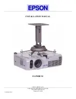
Epson 740c - PowerLite XGA LCD Projector, Installation Manual
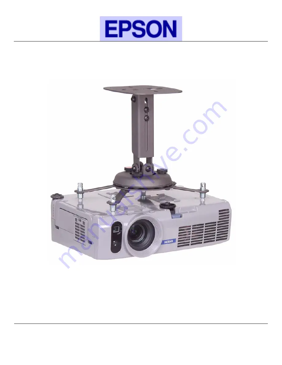
The Epson 740c PowerLite XGA LCD Projector offers a superior visual experience for your presentations and multimedia needs. Make setup a breeze with the included Quick Setup Manual, available for free download from manualshive.com. This comprehensive manual provides step-by-step instructions to ensure smooth operation and maximum performance.
Share
Download

Reviews:
No comments
Related manuals for 740c - PowerLite XGA LCD Projector
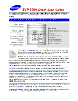
SVP-5300
Brand: Samsung Pages: 4
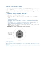
DC100
Brand: Qwizdom Pages: 30
DocCAM 20 HDBT
Brand: VADDIO Pages: 5
DocCAM 20 HDBT
Brand: VADDIO Pages: 18
EV-2000AF
Brand: Elmo Pages: 28

V-VGACON
Brand: Ken A Vision Pages: 2
CE-WR0012-S1
Brand: SIIG Pages: 4
QPC 30M
Brand: Qomo Pages: 10
CeilingVIEW SD CCU
Brand: VADDIO Pages: 16
AVerVision130
Brand: Avermedia Pages: 24
AVER F17
Brand: ICTS Pages: 6
i-Stick
Brand: OPTRON Pages: 36
AVerVision355af
Brand: Avermedia Pages: 43
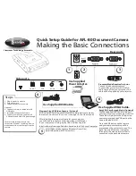
iMMCam AFL-80
Brand: Recordex Pages: 2
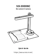
SD-3000NC
Brand: Netum Pages: 6
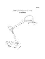
iZiggi-HD
Brand: Ipevo Pages: 10
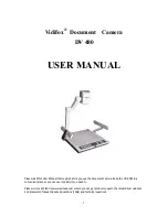
DV 480
Brand: Vidifox Pages: 35
EV-6000AF
Brand: Elmo Pages: 52


