


21D83M-843
Integrated Single Stage
Furnace Control Replacement Kit
FAILURE TO READ AND FOLLOW ALL INSTRUCTIONS CAREFULLY BEFORE
INSTALLING OR OPERATING THIS CONTROL COULD CAUSE PERSONAL
INJURY AND/OR PROPERTY DAMAGE.
DESCRIPTION
PRECAUTIONS
INSTALLATION INSTRUCTIONS
Kit includes:
1 – 50A66-843 ignition control board
1 – Wiring harness (9-pin to 12-pin)
1 – Wiring harness (4-pin to 6-pin)
1 – Mounting panel
4 – Stand-off fasteners
1 – Circuit breaker
1 – 4" blue wire
2 – Wiring diagrams
Installation should be done by a qualified heating and air
conditioning contractor or licensed electrician.
If in doubt about whether your wiring is millivolt, line, or
low voltage, have it inspected by a qualified heating and
air conditioning contractor or licensed electrician.
Do not exceed the specification ratings.
All wiring must conform to local and national electrical
codes and ordinances.
This control is a precision instrument, and should be
handled carefully. Rough handling or distorting compo-
nents could cause the control to malfunction.
Following installation or replacement, follow manufacturer’s
recommended installation/service instructions to ensure
proper operation.
WARNING
!
Failure to comply with the following warnings
could result in personal injury or property damage.
FIRE HAZARD
• Do not exceed the specified voltage.
• Replace existing control with exact model
and dash number.
• Protect the control from direct contact with
water (dripping, spraying, rain, etc.).
• If the control has been in direct contact with
water, replace the control.
• Label all wires before disconnection when
servicing controls. Wiring errors can cause
improper and dangerous operation.
• Route and secure wiring away from flame.
SHOCK HAZARD
• Disconnect electric power before servicing.
• Ensure proper earth grounding of appliance.
• Ensure proper connection of line neutral and
line hot wires.
EXPLOSION HAZARD
• Shut off main gas to appliance until installa-
tion is complete.
CAUTION
!
Do not short out terminals on gas valve or primary
control. Short or incorrect wiring may damage
the thermostat.
The kit includes the 50A66-843 which is an automatic gas
interrupted ignition control that employs a microprocessor
to continually monitor, analyze, and control the proper
operation of the gas burner, inducer, and fan.
These controls incorporate system fault analysis for quick
gas flow shut-off, coupled with automatic ignition retry
upon sensing a fault correction.
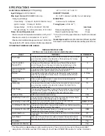
Lennox
White-Rodgers Page
Reference
10M9301
12L6901
32M8801
56L8401
50A65-120
50A65-121
3
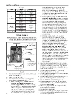
PROCEDURE 1
Figure 1, Picture
1, Table 1, Wiring
Diagram 5001-6973
24L8501
63K8901
97L4801
50A62-120
50A62-121
50A62-820
4
PROCEDURE 2
Figure 1, Picture
2, Table 2, Wiring
Diagram 5001-6972
100925-01
100925-03
17W9201
23W5101
30W2501
69M0801
69M1501
83M00
21D83M-843
50A66-122
50A66-123
5
PROCEDURE 3
The 21D83M-843 kit will replace the following Controls:
Follow instructions for replacement of your model num-
ber under the heading
INSTALLATION.
PART NO. 37-7337C
Replaces 37-7337B
1515
white-rodgers.com
emersonclimate.com


