background image

Vission 20/20

TM

 Micro-controller

Operation and service manual  •  Version 2.7

Summary of Contents for Vilter Vission 20/20

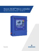
Page 1: ...Vission 20 20TM Micro controller Operation and service manual Version 2 7 ...

Page 2: ......

Page 3: ...ame time the local VilterTM representative or the home office should be notified of any claim made All inquires should include the VilterTM sales order number compressor serial and model number These can be found on the compressor nameplate on the compressor All requests for information services or parts should be directed to VilterTM Manufacturing LLC Customer Service Department 5555 South Packar...

Page 4: ......

Page 5: ...ls 2 2 Wiring Methods 2 3 Best Practices 2 4 Section 3 Hardware Architecture Overview 3 1 Digital Input Output I O 3 1 Analog Inputs 3 6 Analog Outputs 3 7 Digital Analog I O Boards Layout 3 8 Digital Output Boards 3 9 Digital Input Boards 3 10 Digital In Out Boards 3 11 Analog Input Boards 3 12 Analog Input Jumper Tables 3 13 Analog Output Boards 3 15 Section 4 Main Screen Overview 4 1 Top Status...

Page 6: ... 7 2 Freeze Screen 7 2 Logging Event List 7 2 Setpoints 7 2 Add Oil to the Middle Sight Glass 7 8 Analog AUX In 1 16 7 8 Compressor Interlock Trip 7 8 Digital AUX In 1 8 7 8 Discharge Pressure High Discharge Pressure 7 9 Low Discharge Pressure 7 9 Discharge Superheat Temperature High Discharge Superheat Start Temp 7 9 High Discharge Superheat Rise Temp 7 9 High Discharge Superheat Run Temp 7 10 Di...

Page 7: ...ressure 7 17 Suction Superheat Temperature Low Suction Superheat 7 18 Suction Temperature Low Suction Temp 7 18 Volume Position Trip 7 18 Section 8 Timers Overview 8 1 Timer Setpoints 8 1 Section 9 Compressor Scheduling Overview 9 1 Scheduling Setpoint 9 1 Section 10 Compressor Sequencing Overview 10 1 Compressor Sequencing Table 10 1 Status Symbols 10 3 Suction Pressure Control Setpoints 10 4 Pre...

Page 8: ...2 Service Options Overview 12 1 Digital Outputs 12 1 Analog Outputs 12 5 Section 13 Instruments Calibration Overview 13 1 Pressure Control Inputs 13 2 Motor Current 13 2 Remote Capacity 13 5 Analog Inputs 13 5 Analog Outputs 13 7 Section 14 Slide Calibration Overview 14 1 Capacity Slide Valve Potentiometer 14 1 Volume Slide Valve Potentiometer 14 2 Slide Valve Operation 14 2 Calibrate Slide Valve ...

Page 9: ...TU 19 2 Ethernet 19 3 VNC Account 19 3 Anti Recycle 19 4 Restart On Power Failure 19 4 Compressor Sequencing 19 5 Language 19 5 Model Refrigerant 19 5 Compressor Control 19 6 Optional Function Settings 19 6 Condenser Control 19 6 Touchscreen 19 7 Oil Pump 19 8 Oil Cooling 19 8 Motor Current Device 19 8 Alarms and Trips 19 8 Special Compressor Settings 19 8 Daily Auto Back up Settings 19 9 Configur...

Page 10: ...in Screw Control Overview 24 1 Setup Configuration Screen 24 1 Operation 24 2 Slide Calibration Capacity Slide Valve Potentiometer 24 2 Software Limits Setpoints 24 3 Twin Screw Oil Pressure 24 6 Oil Pressure Monitoring BEFORE Compressor Starts 24 6 Low Oil Pressure Safety Bypass 24 6 Oil Pressure Monitoring AFTER Compressor Starts 24 7 Section 25 Cool Compression Control Overview 25 1 Setup 25 1 ...

Page 11: ...pendix B Vission 20 20 Application Procedures Vission 20 20 Application Procedures B 1 Appendix C Remote Control and Monitoring of Vission 20 20 Panel Remote Control and Monitoring of Vission 20 20 Panel C 1 Appendix D Vission 20 20 Communication Table Vission 20 20 Communication Table D 1 Appendix E Abbreviations used on the Vission 20 20 panel screen Abbreviations Table E 1 ...

Page 12: ... 11 Figure 3 8 Analog Input Board Layout 3 12 Figure 3 9 Analog Output Board Layout 3 15 Figure 4 1 Main Screen 4 1 Figure 4 2 Top Status Bar 4 2 Figure 4 3 Parameter Bar 4 3 Figure 4 4 Unit Start Pop Up Window 4 4 Figure 4 5 Bottom Status Bar 4 5 Figure 4 6 Splash Screen 4 6 Figure 4 7 Step VI Screen 4 7 Figure 4 8 SOI Solenoid Screen 4 8 Figure 4 9 Configurable Main Screen with Oil Pump and Oil ...

Page 13: ...s Temperature Control Setpoints 10 5 Figure 10 4 Compressor Sequencing Screen Process Pressure Control Setpoints 10 6 Figure 10 5 Compressor Sequencing Screen Discharge Pressure Control Setpoints Page 2 10 7 Figure 10 6 Compressor Sequencing Screen Device List Page 4 10 8 Figure 10 7 Compressor Sequencing Screen View Detected Devices Page 4 10 9 Figure 10 8 Compressor Sequencing Screen Add Device ...

Page 14: ... VSS Page 2 19 5 Figure 19 3 Configuration Screen Compressor Control Compressor Type VRS Page 2 19 7 Figure 19 4 Configuration Screen Compressor Control Special Compressor Settings Page 2 19 9 Figure 19 5 Configuration Screen Configurable Main Screen Settings Page 3 19 10 Figure 19 6 Configuration Screen Configurable Main Screen Settings Page 4 19 11 Figure 19 7 Configuration Screen Digital Auxili...

Page 15: ...essure and Run Oil Pressure Settings 24 6 Figure 24 7 Timers Menu Twin Screw Control 24 7 Figure 25 1 Configuration Screen 25 1 Figure 25 2 Compressor Control Screen Cool Compression Control Page 2 25 2 Figure 26 1 Remote Oil Cooler Screen Page 1 26 1 Figure 26 2 Remote Oil Cooler VFD Screen Page 2 26 3 Figure 27 1 Vission 20 20 Main Enclosure Electrical Components 27 2 Figure 27 2 Vission 20 20 D...

Page 16: ...B Application Procedures Appendix C Remote Control Appendix D Vission 20 20 Communications Appendix E Abbreviations Used on the Vission 20 20 Panel Screen It is highly recommended that the manual be reviewed prior to servicing the Vission 20 20 system parts Figuresandtablesareincludedtoillustratekeyconcepts Safety precautions are shown throughout the manual They are defined as the following WARNIN...

Page 17: ... 1 Operational Flow Charts 1 of 2 Section 1 Operational Flow Charts Vission 20 20 Operation and Service Manual Emerson 35391SC 2 7 Requirements to Start Compressor Critical Compressor Run Logic at Compressor Start ...

Page 18: ...Vission 20 20 Operation and Service Manual Emerson 35391SC 2 7 Figure 1 1 Operational Flow Charts 2 of 2 Suction Pressure Override Load Limit During Temperature Control High Discharge Pressure Load Limiting Compressor Amperage Load Limiting ...

Page 19: ...es Voltage Source Transformers block a large percentage of Electromagnetic Interference EMI The Vilter Vission 20 20TM should be isolated with its own con trol transformer for the most reliable operation see Figure 2 1 Connecting the Vilter Vission 20 20TM to breaker panels and central control transformers exposes the Vission 20 20 to large amounts of EMI emitted from the other devices connected t...

Page 20: ...xing Voltages Separate different voltages from each other and sep arate AC from DC see Figure 2 4 Figure 2 4 Mixed Voltage Wiring Each voltage level must be run in separate conduit If your installation site has wireways or conduit trays dividers must be installed between the different voltages DC signals If your installation site has wire ways or conduit trays dividers must be installed between th...

Page 21: ...eration and Service Manual Emerson 35391SC 2 7 Figure 2 5 Correct Transformer Wiring Method Wiring Methods Each Vission 20 20 panel should have its own indi vidual control transformer see Figure 2 5 and Figure 2 6 Figure 2 6 Incorrect Transformer Wiring Method ...

Page 22: ...ing transformers or UPS devices that will power the Vission 2020 panel The Vission 2020 panel contains two power supplies Total power supply load 90 watts 1 1 24VDC 2 2 A 53 watts 2 1 dual output 12V 1 amp 5V 4A 35 watts The DC loads that are attached to the power supplies breakdown like this 1 Each actuator 24VDC 20mA ea x2 40 mA 2 Each press transducer 24VDC 30 mA ea x4 120 mA 3 Each RTD negligi...

Page 23: ... this output is de energized Capacity Increase Output This output is only active when the compressor is running When the Vission 20 20 determines that the compressor should increase capacity by moving the slide valve to a higher percentage this output is energized Once the slide valve reaches 100 this output will not energize Capacity Decrease Output This output is only active when the compressor ...

Page 24: ...int 2 the output is de energized Alarm Output This output is energized when the system has no alarms If an alarm is issued the output de energizes and stays de energized until the alarm condition is cleared Economizer Port 2 Output This output is energized when the compressor slide valve percentage is equal to or greater than slide valve set point for economizer port 2 It is de ener gized when the...

Page 25: ...nomizer Port 2 OUTPUT 2 13 Liquid Injection 1 OUTPUT 2 14 Liquid Injection 2 OUTPUT 2 15 Remote Enabled OUTPUT 2 16 Shunt Trip OUTPUT 3 17 Comp Motor Starter Auxiliary Contact INPUT 3 18 High Level Shutdown INPUT 3 19 Oil Level Float Switch 1 INPUT 3 20 Oil Level Float Switch 2 INPUT 3 21 Remote Setpoint 1 2 Selection INPUT 3 22 Remote Start Stop INPUT 3 23 Remote Capacity Increase INPUT 3 24 Remo...

Page 26: ... Float Switch 2 Input This input must be energized in order for the com pressor to operate If de energized the compressor will shut down and issue a oil level 2 trip Remote Select 1 2 Input This input enables or disables remote I O control Energizing this input enables the Remote Capacity Increase and Remote Capacity Decrease inputs Remote Start Stop Input If the compressor is enabled for remote I...

Page 27: ...re 4 20 mA RTD ICTD 7 15 Condenser Pressure 0 5V 1 5 V 0 10V 4 20 mA RTD ICTD 7 16 Remote Caphold Setpoint 0 5V 4 20 mA RTD ICTD 8 17 Auxiliary 1 0 5V 1 5 V 0 10V 4 20 mA RTD ICTD 8 18 Auxiliary 2 0 5V 1 5 V 0 10V 4 20 mA RTD ICTD 8 19 Auxiliary 3 0 5V 1 5 V 0 10V 4 20 mA RTD ICTD 8 20 Auxiliary 4 0 5V 1 5 V 0 10V 4 20 mA RTD ICTD 8 21 Auxiliary 5 0 5V 1 5 V 0 10V 4 20 mA RTD ICTD 8 22 Auxiliary 6...

Page 28: ...libration screen Oil Filter Inlet Pressure Default signal is 4 20mA Oil filter pressure trans ducer range and calibration are set in the calibration screen Oil Manifold Pressure Default signal is 4 20mA Oil manifold pressure trans ducer range and calibration are set in the calibration screen Economizer Pressure Default signal is 4 20mA Economizer pressure trans ducer range and calibration are set ...

Page 29: ...ansmits the slide valve position for remote monitoring Motorized Valve V For a cool compression compressor this 4 20mA signal controls a motorized valve to regulate the liq uid refrigerant level in the oil separator For a liquid injection application on a standard single screw this 4 20mA signal controls a motorized valve to regulate the liquid refrigerant injected into the compressor for oil cool...

Page 30: ...ry 16 0 5V 1 5 V 0 10V 4 20 mA RTD ICTD Table 3 2 Analog Inputs 2 of 2 Digital Analog I O Boards Layout It is important to install the boards in the proper layout For the correct digital and analog input output I O board layout see Figure 3 4 Dipswitches Each board has a dipswitch which sets its communi cations address so that it can communicate with the CPU board The dipswitch settings must be co...

Page 31: ...hese LEDs in dicate when a 120VAC output is being produced Voltage LEDs Marked in the diagram below in Orange These LEDs indicate the correct voltage of both the 5V DC and 24V DC power sources Communication LEDs Marked in the diagram below in Green These LEDs show the active communications between the digital output board and the Vission 20 20 CPU board Address Dipswitches Markedinthediagrambelowi...

Page 32: ...EDs indicate when a 120VAC input is detected Voltage LEDs Marked in the diagram below in Orange These LEDs indicate the correct voltage of both the 5V DC and 24V DC power sources Communication LEDs Marked in the diagram below in Green These LEDs show the active communications between the digital output board and the Vission 20 20 CPU board Address Dipswitches Marked in the diagram below in Red The...

Page 33: ...light blue for inputs These LEDs indicate when a 120VAC output is being produced or a 120VAC signal is detected Voltage LEDs Marked in the diagram below in Orange These LEDs indicate the correct voltage of both the 5V DC and 24V DC power sources Communication LEDs Marked in the diagram below in Green These LEDs show the active communications between the digital output board and the Vission 20 20 C...

Page 34: ...ange for incoming analog signals For the correct jumper setting for a giving application see Table 3 4 Analog Input Jumper Tables Voltage LEDs Marked in the diagram below in Orange These LEDs indicate the correct voltage of both the 5V DC and 24V DC power sources Communication LEDs Marked in the diagram below in Green These LEDs show the active communications between the digital output board and t...

Page 35: ... 5 AMP secondary current transformers are installed in the motor starter Use Analog Input 1 B when current transformers are installed in the motor starter CHANNEL 2 SIGNAL JP 4 JP 5 JP 6 JP 28 Analog Input 2 0 5 VOLT OUT OUT OUT OUT 1 5 VOLT OUT OUT OUT OUT 0 10 VOLT OUT OUT IN OUT 4 20 mA IN OUT OUT OUT ICTD OUT IN OUT OUT RTD OUT OUT OUT IN CHANNEL 3 SIGNAL JP 7 JP 8 JP 9 JP 29 Analog Input 3 0 ...

Page 36: ...EL 7 SIGNAL JP 19 JP 20 JP 21 JP 33 JP 25 Analog input 7 0 5 VOLT OUT OUT OUT OUT 2 1 5 VOLT OUT OUT OUT OUT 2 0 10 VOLT OUT OUT IN OUT 2 4 20 mA IN OUT OUT OUT 2 ICTD OUT IN OUT OUT 2 RTD OUT OUT OUT IN 2 ACTUATOR OUT OUT OUT OUT 1 POTENTIOMETER OUT OUT OUT OUT 3 LPI IN OUT OUT OUT 1 CHANNEL 8 SIGNAL JP 22 JP 23 JP 24 JP 34 JP 26 Analog Input 8 0 5 VOLT OUT OUT OUT OUT 2 1 5 VOLT OUT OUT OUT OUT ...

Page 37: ...LEDs indicate the correct voltage of both the 5V DC and 24V DC power sources Communication LEDs Marked in the diagram below in Green These LEDs show the active communications between the digital output board and the Vission 20 20 CPU board Address Dipswitches MarkedinthediagrambelowinRed Thesedipswitch es are used to assign each board its address position The addresses are binary and therefore the...

Page 38: ...f the sections are static Top Status Bar Bottom Status Bar and Parameters Bar These three sec tions of the main screen will remain visible while navigat ing through other screens and provide a constant view of critical information The splash screen is the only dy namic section All navigation to any other screens will be performed through the Main Screen NOTE Because of space constrains the full te...

Page 39: ...hat the compressor motor is currently running Information Bars will flash their information over the top of the status bar The operator will see the status bar and then one or more information bars in a repetitive sequence Information Bar blue Shows various operational modes that are different than normal running condition An example of this would be a load limit condition The compressor is not ab...

Page 40: ...ray bar In some cases the increase and decrease buttons will appear below the volume indicator The buttons only appear if the op erator who is logged on has sufficient privileges If available the buttons work to increase and decrease the volume slide position in the same manner as the capacity slide Stop Button When pressed stops the compressor in all cases Remote Lock Out Button When pressed acti...

Page 41: ...city control this box will show the desired capacity position The suction box shows the current suction pressure and suction temperature The discharge box shows the current dis charge pressure and discharge temperature The oil box shows the pressure differential which is calculated as oil filter out pressure mi nus suction pressure Filter differential is calcu lated as oil filter in pressure minus...

Page 42: ...This button takes the operator to the login screen to create additional users or log in Log off Button Pressing the log off button logs off the current user if any are logged in Help Button Pressing the help button takes the operator to the help screen where the operation and service manual can be read and where there s access to program in formation as well Status Bars The information available i...

Page 43: ... oil in the separator Cap Displays the position of the capacity slide from 0 to 100 Process When the Process control is selected as the control mode this box will appear and display either of the process temperature or process pressure depending on process control mode selection Vol Displays the position of the volume slide from 0 to 100 Anti Recycle Displays the anti recycle time if applicable Oi...

Page 44: ...t as Step VI Refer to Section 6 Compressor Control for more on Step VI Low VI Displays the current status of Low VI Digital Output This will be displayed only when the VI control meth od is set as Step VI High VI Displays the current status of High VI Digital Output This will be displayed only when the VI control meth od is set as Step VI Figure 4 7 Step VI Screen ...

Page 45: ...d Displays the current status of SOI Solenoid Digital Output This will be displayed instead of Oil Pump when the SOI Solenoid Feature is enabled from Configuration Screen NOTE The On state for digital outputs on the main screen will be displayed with a Green Background while the Off state for digital outputs will be displayed with an Orange Background Figure 4 8 SOI Solenoid Screen ...

Page 46: ...has four tables The top left corner table will display values such as Anti Recycle Time State for the Oil Pump Oil Heater SOI Solenoid Separator Level Low VI High VI Remote Lock Out Digital Outputs Please see Figures 4 9 4 10 4 11 4 12 Theother3Tablesareuser configuredandwilldisplayval ues as per the settings in pages 3 4 of the configuration screen Please see Figure 4 9 No values will be displaye...

Page 47: ...ain Screen Vission 20 20 Operation and Service Manual Emerson 35391SC 2 7 Figure 4 10 Configurable Main Screen with SOI Solenoid and Oil Heater Figure 4 11 Configurable Main Screen with SOI Solenoid and Separator Level ...

Page 48: ...4 11 Section 4 Main Screen Vission 20 20 Operation and Service Manual Emerson 35391SC 2 7 Figure 4 12 Configurable Main Screen with Step VI Figure 4 13 Configurable Main Screen Default View ...

Page 49: ...or can set the various time related parameters Compressor Scheduling Navigates to the compressor scheduling screen where the operator can set the scheduler to change the control method at settable dates and times Compressor Sequencing Navigates to the compressor sequencing screen where the operator can set up compressor to se quence up to nine other compressors This is also sometimes known as lead...

Page 50: ... States Allows viewing of the live data of all analog and digi tal input and outputs Also allows viewing of a snap shot of all analog and digital input and outputs at the time of the last compressor fault event Auxiliary I O Navigates to the auxiliary I O screen where an op erator can configure any auxiliary instruments or devices Configuration Navigates to configuration screens where the initial ...

Page 51: ...operator to tune these settings to achieve the best operation Suction Pressure Control Process Temperature Control Process Pressure Control and Discharge Pressure Control The Vission 20 20 uses a pulse proportional control method to control the compressor capacity slide valve in order to maintain the control setpoint The control setpoint can either be the suction pressure control set point process...

Page 52: ...ng loads if desired see Figure 6 4 The Deadband Setpoint defines the area around the con trol setpoint where the algorithm stops adjusting the capacity slide This area is a percentage of the propor tional band By default the proportional band is set to 4 Psig and the deadband is set to 10 of 4 Psig Making the deadband 0 4 Psig of the control setpoint Once the process variable is within the deadban...

Page 53: ...eature is enabled the Auto cycle setpoints are automatically disabled Pump down mode will cause the compressor to cycle off via the Pumpdown Stop Pressure setpoint and will not allow the compressor to start again Enable Enables the Auto cycle control Uncheck the box to disable the Auto cycle setpoints Start Pressure When the suction pressure meets or exceeds this set point the compressor will star...

Page 54: ...6 4 Section 6 Compressor Control Vission 20 20 Operation and Service Manual Emerson 35391SC 2 7 Figure 6 4 Proportional Band Setpoint Figure 6 5 Compressor Control Screen Discharge Pressure Control ...

Page 55: ...n the unloading direction the motor speed will ramp down to its minimum speed and then the capacity slide will move to its minimum position The two step control method works much like the one step method but divides the control into four sections see Figure 6 8 While loading the compressor will first move the capacity slide to the maximum set for step one then speed up the motor to its maximum spe...

Page 56: ...djust the motor speed action in direct pro portion to the difference between the control set point and the process variable SP PV error This is a unitless quantity and is used for coarse adjustment This setpoint should be set to the lowest value that gives adequate control system response Increasing the proportional setting increases the control sys tem s sensitivity to small process fluctuations ...

Page 57: ...00 RPM Oil Restriction Setpoint ThisisCompressorVFDRPMsetpointusedforturning ON OFF the Oil Solenoid Digital Output Oil Solenoid Digital Output is turned ON when Compressor is Running and Compressor VFD RPM goes below this setpoint Oil Restriction Differential This is the differential around Oil Restriction Setpoint State Below Setpoint This is the Oil Restriction Solenoid State selection Setpoint...

Page 58: ...t any point changes are made to your application configuration or equipment you will need to consult a VilterTM engineer on how to apply those changes to the use of the Rapid Cycling VFD Control feature The VFD page is where the operator can tune the motor VFD for desired rapid cycling VFD operation see Figure 6 10 A VilterTM compressor uses the variable speed of a VFD controlled motor to vary the...

Page 59: ... the compressor to cycle off via the Pumpdown Stop Pressure setpoint Normally the Pumpdown Stop Pressure setpoint will be set lower than the Auto cycle Stop setpoint Therefore as the suction pressure is pulled down the compressor is prevented from shutting down prematurely via the Auto cycle Stop setpoint by automatically ignoring the Auto cycle feature The compressor will be placed into Stop mode...

Page 60: ...ssor is running in local Auto Auto Sequencing mode and when the Control mode is Suction Pressure 1 The Pulldown feature provides a method to slowly pull the suction pressure down to operating conditions The pulldown method used is to step the suction pressure down over a defined time interval Example Assume the suction pressure is at 85 psig and the set point we want to get to is 20 psig The opera...

Page 61: ...is setpoint defines the offset pressure values for Auto Cycle Start Pressure and Stop Pressure from the Suction Pressure setpoint The Auto Cycle Start Pressure setpoint will be the Suction Pressure set point increased by this setpoint pressure value while the Auto Cycle Stop Pressure value will be the Suction Pressure setpoint decremented by this setpoint pres sure value When the Pulldown feature ...

Page 62: ...12 Oil Pump Press Restart Ratio The on and off setpoints define when the oil pump will cycle on and off if the oil pump is selected to cycle from the configuration screen Oil Separator Heater Temp When the oil temperature falls below this setpoint the oil heater will turn on Note there is a 5 F dif ferential associated with this setpoint For example when set at 100 F the heater will turn on at 95 ...

Page 63: ... started or when the SOI Solenoid is Cycled On when the compressor is running SOI Load Limit This setpoint defines the maximum value for the ca pacity slide position when SOI Solenoid is ON No Oil Pump RefertoFigure6 14fortheNoOilPumpControlSetpoints When No Pump is selected in the Configuration Screen the Oil Pump digital Output is Forced OFF No Oil Pump Pressure Ratio This setpoint defines the l...

Page 64: ...m recognizes a potential trip and either stops the compressor from loading up or even unloads the compressor to prevent the trip Stop load When this value is reached the capacity slide will not advance in any condition Force Unload When this value is reached the capacity slide posi tion will decrease until the variable reading is below this value High Motor Amps The motor current values for stop l...

Page 65: ... labels for the each output Only the Economizer Port 2 label is non editable Slide Indicates the capacity slide position where the digital output is triggered State Below Setpoint Defines the state of the digital output when the slide position is below the Slide setpoint The operator can choose between N O or N C This setpoint is not available for the Economizer Port 2 so the Economizer Port 2 fol...

Page 66: ... separator temper ature meets or exceeds the value of Oil Sep Temp Override The injection solenoid will deactivate if ei ther setpoints are not met This will prevent situations where the discharge temperature may rise quickly but the oil temperature is still very cold By preventing the liquid injection solenoid from turning on at this point the oil separator will not be subjected to additional liq...

Page 67: ...he temperature the oil must reach before the liquid injection solenoid is allowed to be activated P Proportional Gain Used to adjust the positioning valve in direct propor tion to the difference between the control setpoint and the discharge temperature SP DT error The proportional term is a unitless quantity and is used for coarse adjustment This setpoint should be set to the lowest value that gi...

Page 68: ...l Liquid Injection Feature The Enable Disable functionality of this box depends on Selected Compressor Type and Model in the Configuration Screen Valve Loss This Setpoint defines the Valve Train Loss for the Dual Liquid Injection Feature Safety Loss This Setpoint defines the Safety Loss for the Dual Liquid Injection Feature Slide ThisSetpointdefinesSlide Value TheLiquidInjection 2 digital output d...

Page 69: ... se lect which port is the preferred Pre Start Up outlet posi tion The valve shall be at the lowest pressure outlet posi tion at Pre Start Up i e low or medium depending on tubing positions In the SIG CCW position the actuator moves CCW when the signal is energized during operation based on the switch pressure until it reaches the limit this makes the 3 o clock port the outlet port Figure 6 17 rig...

Page 70: ...ere VI Control settings can be con figured This feature is only available for Twin Screw Compressors There are three types of VI Control meth ods which can be configured as follows Fixed VI If this method is selected then there will be no vol ume control for Twin Screw compressors Figure 6 18 Compressor Control Screen Fixed VI Twin Screw ...

Page 71: ... 2 Maximum VI This setpoint defines the maximum slide position value 100 for volume slide valve The default value for Maximum VI is 5 0 Figure 6 19 Compressor Control Screen Continuous VI Twin Screw Deadband This setpoint defines the deadband for the calcula tion of the volume slide position Volume will not be changed till the Volume Ratio changes by this amount The default value for Deadband is 0...

Page 72: ...alue is used for calculation of Step 2 Step 3 Digital Outputs When Volume Ratio is greater than average of Step 1 Step 2 and also less than average of Step 2 Step 3 Low VI Digital Output will be OFF and High VI Digital Output will be ON Step 3 This setpoint defines the maximum step value for Step VI control The default value for Step 3 is 5 0 This value is used for calculation of Step 2 Step 3 Dig...

Page 73: ...played when a warning condition is present and the bottom status bar used for displaying warnings is pressed Inhibits The Vission 20 20 uses several start Inhibits to prevent the compressor from starting to protect the compres sor and the refrigeration system Inhibits are only active during Pre Start condition While starting the compres sor the Inhibits are checked first before the oil pump is sta...

Page 74: ...s a red banners on the top and bottom status bars Freeze Screens Trips also trigger the input output screen to take a snap shot of all input and output values as Freeze 1 screen The five most recent Freeze screens are saved The Freeze screens are available as left side tabs in the input output screens and are very useful as a troubleshooting tool for the operator Refer to Section 17 Figure 17 7 fo...

Page 75: ...7 3 Section 7 Alarms and Trips Vission 20 20 Operation and Service Manual Emerson 35391SC 2 7 Figure 7 3 Alarms and Trips Screen Page 1 Process Pressure ...

Page 76: ...7 4 Section 7 Alarms and Trips Vission 20 20 Operation and Service Manual Emerson 35391SC 2 7 Figure 7 4 Alarms and Trips Screen Page 2 ...

Page 77: ...7 5 Section 7 Alarms and Trips Vission 20 20 Operation and Service Manual Emerson 35391SC 2 7 Figure 7 5 Alarms and Trips Screen Page 2 Cool Compression ...

Page 78: ...7 6 Section 7 Alarms and Trips Vission 20 20 Operation and Service Manual Emerson 35391SC 2 7 Figure 7 6 Alarms and Trips Screen Page 3 ...

Page 79: ...7 7 Section 7 Alarms and Trips Vission 20 20 Operation and Service Manual Emerson 35391SC 2 7 Figure 7 7 Alarms and Trips Screen Page 3 SOI Solenoid ...

Page 80: ...7 8 Section 7 Alarms and Trips Vission 20 20 Operation and Service Manual Emerson 35391SC 2 7 Figure 7 8 Alarms and Trips Screen Page 3 No Oil Pump ...

Page 81: ...7 9 Section 7 Alarms and Trips Vission 20 20 Operation and Service Manual Emerson 35391SC 2 7 Figure 7 9 Alarms and Trips Screen Page 3 Cool Compression ...

Page 82: ...pear if the condition exists following any shutdown Capacity Position Trip Capacity Slides failing to unload 5 during Capacity Unload Cycle Compressor Interlock Trip Compressor Interlock Trip message will appear if the Motor Auxiliary contact fails to close before the Compressor Starter Auxiliary Contact Bypass timer times out Refer to the wiring diagram provided with unit Compressor Interlock Inh...

Page 83: ...ation screen Superheat Temperature depends on Discharge Pressure and Discharge Temperature High Discharge Superheat Start Temp Discharge Superheat Temperature This message will appear when the Discharge Superheat Temperature exceeds the safety setting of the High Superheat Start Temp Trip Setpoint See Figure 7 5 High Superheat Temp Warning High Superheat Temp Inhibit High Superheat Start Temp Trip...

Page 84: ...Figure 7 5 High Discharge Temp Warning High Discharge Temp Inhibit High Discharge Temp Alarm High Discharge Temp Trip Discharge Temperature High Discharge Temperature Alarm Discharge Temperature High Discharge Temperature Alarm Discharge Temperature High Discharge Temperature Alarm Discharge Temperature High Discharge Temperature Trip Low Discharge Temp Discharge Temperature This is not a user adj...

Page 85: ... Differential Pressure Safety Changeover Timer times out This safety setpoint is active when the compressor has started and the Filter Diff Pressure Safety Changeover timer has timed out See Figure 7 6 High Filter Differential Alarm High Filter Differential Trip Filter Differential Pressure High Filter Differential Run Pressure Alarm Filter Differential Pressure High Filter Differential Run Pressu...

Page 86: ...bit High Oil Injection Temp Alarm High Oil Injection Temp Trip Oil Injection Temperature High Oil Injection Temperature Alarm Oil Injection Temperature High Oil Injection Temperature Alarm Oil Injection Temperature High Oil Injection Temperature Alarm Oil Injection Temperature High Oil Injection Temperature Trip Low Oil Injection Temp Oil Injection Temperature The Alarm and Trip Setpoints are bypa...

Page 87: ...ssor starts After the Oil Pressure Bypass Timer has expired the Oil Pressure must be above the normal setpoints or else an Alarm or Trip will occur An alarm or trip will be active if the oil pressure drops below the normal setpoint values after the Oil Pressure Bypass timer has expired This time limit is set on the Timer menu screen Run oil pressure is defined as manifold pressure minus suction pr...

Page 88: ...r timer this safety is deactivated and the Low Oil Separator Run Temperature alarm and safety Setpoints become active See Figure 7 5 Low Oil Separator Start Temp Warning Low Oil Separator Start Temp Inhibit Low Oil Separator Temp Alarm Low Oil Separator Temp Trip Oil Separator Temperature Low Oil Separator Start Temperature Alarm Oil Separator Temperature Low Oil Separator Start Temperature Alarm ...

Page 89: ...activates for Cycling and Full Time Oil Pump selection See Figure 7 6 Prelube Oil Pump Inhibit Prelube Oil Pressure Trip Pre Lube Pressure Low Pre Lube Pressure Alarm Pre Lube Pressure Manifold Discharge Low Pre Lube Pressure Process Pressure This option is only available for Process Pressure Control mode selected in the Control Mode dropdown selec tion found in the Compressor Control screen High ...

Page 90: ...Process Temperature Alarm Setpoint 1 or 2 Process Temperature Low Process Temperature Trip Setpoint 1 or 2 Compressor started in Remote Mode Remote Comm Time Out Remote Comm Time Out Alarm Remote Comm Time Out Trip Remote Comm Inactive Time Communication Failure Detect Timer Remote Comm Inactive Time Communication Failure Detect Timer Remote Comm Time Out On a Communication Failure is configured a...

Page 91: ...ow Pressure Ratio Trip Starter Starter Shutdown Trip Starter Problem Low Suction Pressure Suction Pressure This message will appear when Suction Pressure falls below the safety setting of Low Suction Pressure Alarm or Trip Setpoint 1 or 2 This safety is active in both temperature and pressure control modes See Figure 7 2 Low Suction Pressure Warning Low Suction Pressure Inhibit Low Suction Pressur...

Page 92: ...ion Temperature Low Suction Temperature Alarm Suction Temperature Low Suction Temperature Alarm Suction Temperature Low Suction Temperature Alarm Suction Temperature Low Suction Temperature Trip Volume Position Trip This message will appear if condition exists following any shutdown See Figure 7 5 Volume Position Trip Volume Slides failing to un load 5 during Volume Unload Cycle Warnings Inhibits ...

Page 93: ...ed and then the time has expired Delays Delays require the condition to occur for the speci fied amount of time Timers A general timer requiring the time to expire before the listed event can occur Timer Setpoints Capacity Increase Start Delay At compressor startup the capacity slide position is held at minimum position for this time period This is to allow compressor and system conditions to stab...

Page 94: ... and a trip message will be displayed This timer is available if the unit is equipped with a low oil separator float switch the oil level switch is standard on all liquid injection units and optional on all others Low Oil Separator Temperature Safety Changeover ThistimerallowsLowOilSeparatorStartTemperature safety setpoint to protect the compressor against cold oil during starting After the timer ...

Page 95: ...fore setting a trip condition High Motor Amps Safety Bypass Starting motors can typically pull much more than its rates full load amps for a short time This timer ig nores that sudden inrush of current for the specified time Emergency Stop Timer Defines the amount of time the compressor is in a False start condition before activating the Emergency stop The emergency stop output can be connected to...

Page 96: ...es the SOI Low Oil Pressure Safety set points during start up After the timer expires the SOI Low Oil Pressure safety is active SOI Low Pressure Ratio Safety Bypass This timer bypasses the SOI Low Pressure Ratio Safety set points during start up After the timer expires the SOI Low Pressure Ratio safety is active Figure 8 3 Timers Screen Page 2 SOI Solenoid ...

Page 97: ...art Oil Pressure Stage 1 Pressure Trip Setpoint This Setpoint is configurable only when No Pump is selected in Configuration Screen Start Oil Pressure Stage 2 Safety Timer This timer starts when compressor is started Once this timer is lapsed Oil Pressure will get monitored against Start Oil Pressure Stage 2 Pressure Trip Setpoint This Setpoint is configurable only when No Pump is selected in Conf...

Page 98: ...rder invalid events are marked with caution symbol to indicate the operator to correct events and then enable feature Control Mode These drop down boxes allow selection of operating modes which get switched once schedule event time is achieved The list of allowable modes depends on the number of controllers selected in the configuration screen For example if the number of Suction Pressure Control ...

Page 99: ...r format and 0 23 for 24 hour for mat The range of values allowed to set for Minutes setpoint is 0 59 AM PM selection is active for se lection only when Time Format selected in configura tion screen is 12 hour When the scheduling feature is enabled and No of controllers for Suction Pressure Control Process Temperature Control are changed in configuration screen which makes control modes selected i...

Page 100: ... Device Name This is a read only value The device Name can be changed from the Configuration Screen as long as an actual name is chosen it can t be empty Min Trigger Defines the Master s capacity value in percentage which is used as a trigger to step wise decrease the slave s compressor capacity Slave compressor ca pacity is decreased only if the Master is running with capacity lower than set Min ...

Page 101: ...se the last step makes the total ca pacity greater than the maximum capacity total ca pacity will get reduced to maximum capacity Same is applicable when the last step makes the total ca pacity lower than the minimum capacity then mini mum capacity takes priority Min Cap Defines the lowest capacity in percentage at which a compressor is allowed to run Minimum capacity value has precedence over fir...

Page 102: ...error Slave Compressor under active control of Master Compressor Slave Compressor running into its stop timer will be stopped Slave Compressor is next in sequence for unloading Slave Compressor running into its start timer will be started Status Symbols Compressor sequencing status symbols are automati cally refreshed every 10 seconds For symbols see Table 10 1 NOTE Before configuring the Sequenci...

Page 103: ...g to the Fast Load Timer Fast Unload Pressure Offset Defines the offset from suction pressure control set point to monitor compressor load If suction pressure drops below this setpoint s value then sequencing decisions are made according to Fast Unload Timer CAPACITY LOAD UNLOAD TIMERS One of the following Capacity Load Unload timers is used to make sequencing decisions periodically Suction Pressu...

Page 104: ...st Load Temp Offset Defines the offset from the process temperature con trol setpoint to monitor compressor load If process temperature surpasses this setpoint s value then the Figure 10 3 Compressor Sequencing Screen Process Control Setpoints for Temperature sequencing decisions are made according to Fast Load Timer Fast Unload Pressure Offset Defines the offset from the process temperature contr...

Page 105: ... sequencing algorithm allows the starting and loading of slave compressors to cater for increasing load requirements Setpoint The target setpoint is a read only value here This setpoint can be changed by logging on to the Compressor Control Screen Fast Load Temp Offset Defines the offset from the process pressure control setpointtomonitorcompressorload Ifprocesspres sure surpasses this setpoint s ...

Page 106: ...mersisused to make sequencing decisions periodically Discharge Pressure setpoints are monitored to identify which one of the following timers to be used Slow Load Timer If discharge pressure drops below the discharge Fast Load Timer If process pressure surpasses the fast load temp off set setpoint then this timer s value is used to make periodic sequencing decisions Slow Unload Timer If process pr...

Page 107: ...If discharge pressure surpasses the fast unload pres sure offset setpoint then this timer s value is used to make periodic sequencing decisions Devices List This screen is designed to add display delete and test connection with slave compressors that are used by the master compressor for sequencing For Devices List screen see Figure 10 6 DEVICES LIST COLUMNS Device Name Displays the Name of the Sl...

Page 108: ...ices are shown by the Master compressor as in Figure 10 7 Device Name Displays the Name of the Detected Device IP Address Displays the IP Address of the Detected Device Device ID Displays the Device ID of the Detected Device CFM Displays the CFM of the Detected Device Add Checkbox to select the Detected Device Figure 10 7 Compressor Sequencing Screen View Detected Devices Page 4 OK This button all...

Page 109: ...ice List Screen A Vission device can be added as a Slave compressor by the Master compressor from this screen as shown in Figure 10 8 Device Name Entry box to set the Name of a Vission Device IP Address Entry box to set the IP Address of a Vission Device Device ID Entry box to set the Device ID of a Vission Device CFM Drop down box to set the CFM of a Vission Device OK This button allows the addit...

Page 110: ...This popup is displayed when clicking the Delete Device button in the Device List Screen Slave compressors can be removed from the sequencing network by the Master Compressor from this screen as shown in Figure 10 9 Yes This button allows the deletion of a Slave Compressor from the Sequencing Network No ThisbuttoncancelsthedeletionofaSlaveCompressor from the Sequencing Network ...

Page 111: ...or Sequencing Screen Test Connection Test Connection The Master Compressor offers an easy way to test the physical connection with the slave compressors This can be mainly used for troubleshooting slave devices in the network By clicking the Test Connection button the connection result is displayed as shown in Figure 10 10 ...

Page 112: ... the Sequencing Network For the Sync Sequencing Parameters screen see Figure 10 11 Sync By pressing this button the Vission device s informa tion is sent over the network to the Vission 20 20 Slave Compressors NOTE Follow these steps to use this feature 1 Sync Data by pressing the Sync Button in the Master compressor 2 Change the intended Vission 20 20 Slave Compressor to Master Compressor from th...

Page 113: ...ooting see Figure 10 12 This screen Is divided into four columns and can list up to 256 separate events The operator can download the information on the sequencing event list through the Data Backup Screen EVENTS LIST COLUMNS Date Displays the date of the event in MM DD YYYY format Time Displays the time of the event in HH MM SS format Event Type Displays the type of message for a particular listi...

Page 114: ...odbus TCP protocol Assign a unique Ethernet IP address SETTING UP THE SLAVE COMPRESSORS FOR SEQUENCING 1 Log onto each of the slave compressors one by one and navigate to the Configuration screen see Figure 10 13 2 Enable the Ethernet port and select the Modbus TCP protocol 3 Set up a unique Ethernet IP address for each slave 4 Set up the Subnet Mask for the IP address 5 Set up the Gateway address...

Page 115: ...s information over the network at a rate of every 15 seconds After the Master Compressor is con figured the slave information will be populated in the Sequencing menu of the Master Compressor 11 Exit out of the configuration screen and then put the slave in Remote mode by pressing Unit Start Remote see Figure 10 14 Figure 10 14 Placing Slave Compressors into Remote Mode ...

Page 116: ...address for the master 3 Setup the Subnet Mask for the IP address 4 Setup the Gateway address MUST DO 5 Enable the Compressor Sequencing check box and select Master 6 Select a Network Name for the master compressor Network Name must be same for Master Slave Compressors 7 Select a Unique Name for the master compressor 8 Set the Communications Active Remote Control to ETHERNET 9 Apply these settings...

Page 117: ...um speed if additional capacity is needed the next fan or pump is turned on The VFD will modulate down and then once it is back up to 100 again then the next fan or pump is turned on This method allows the smoothest condenser control by spacing the VFD between the fan and pump steps while maintaining a condenser pressure that matches the setpoint Condenser Control Setpoint Run Mode Run Mode allows...

Page 118: ...eed Fan Delay This is a time delay for the fan spin down in case of 2 speed motor dual speed fan Summer Winter Auto Switch This checkbox when enabled allows profiles to switch automatically depending on the ambient temperature setpoint when Run Mode is Auto When ambient temperature falls below the ambient temperature setpoint winter profile is used Similarly when ambient temperature is above the a...

Page 119: ...lue that gives adequate control system re sponse Increasing the proportional setting increases the control system s sensitivity to small process fluc tuations and the tendency to hunt I Integral reset Used to adjust the capacity control action integrat ing the error over time to account for a small er ror that has persisted for a long time This quantity is used for fine adjustment This setpoint is...

Page 120: ...11 4 Section 11 Condenser Control Vission 20 20 Operation and Service Manual Emerson 35391SC 2 7 Figure 11 2 Condenser Control Screen Page 2 ...

Page 121: ...tput at the terminal block or view the output by watching the LEDs located on the cards For Digital Output screens see Figures 12 1 12 2 12 3 and 12 4 Reference Figure 12 1 Compressor Start Activates the output assigned to the compressor motor starter The output is connected to terminal 11 and is the 1st LED on card 1 Oil Pump Start Activates the output assigned to the oil pump The output is conne...

Page 122: ...ut The output is connected to terminal 18 and is the bottom LED on card 1 Reference Figure 12 2 Slide Valve Setpoint 1 Economizer Activates the output typically assigned to the econo mizer solenoid but can be changed by the operator The output is connected to terminal 21 and is the 1st LED on card 2 Slide Valve Setpoint 2 Hot Gas Bypass Activates the output typically assigned to the hot gas bypass...

Page 123: ...y stop timer has expired This output could be wired to a breaker with a shunt trip that feeds power to a starter to force a shutdown The output is connected to terminal 28 and is the 8th LED on card 2 Reference Figure 12 3 and Figure 12 4 Condenser Remote Oil Cooler Step 1 Activates the output assigned to the 1st step of the Condenser Remote Oil Cooler The output is con nected to terminal 41 and i...

Page 124: ...n 35391SC 2 7 Condenser Remote Oil Cooler Step 4 Activates the output assigned to the 4th step of the Condenser Remote Oil Cooler The output is con nected to terminal 44 and is the 4th LED down on card 4 Figure 12 4 Service Options Screen Digital Outputs for Remote Oil Cooler Page 3 ...

Page 125: ...or VFD The output is connected to AO 1 on card 10 Condenser Remote Oil Cooler VFD Sets the analog output assigned to the Condenser Remote Oil Cooler VFD The output is connected to AO 2 on card 10 Slide Valve Position Figure 12 5 Service Options Screen Analog Outputs Page 4 Sets the analog output assigned to the Slide Valve po sition used to inform a central control system of the capacity position ...

Page 126: ...point will effect what value is shown All instruments are calibrated using a two point linear calibration process Any device that has a non linear re sponse to environmental stimuli will not be able to be calibrated through the Vission 20 20 Pressure and Temperature Inputs The most commonly used instruments are tempera ture and pressure sensors The first two pages of the Instrument Calibration scr...

Page 127: ...re or Pressure depending on the selected control model The tab is divided into two sections Device Calibration and Channel Calibration with Default and Custom Devices as well as Offset and Range Calibration features as described for the standard Pressure and Temperature Inputs Motor Current The Vission 20 20 has two options for measuring motor current A 4 20mA signal transmitted from an external d...

Page 128: ...ented by a 20mA input Enter Desired Value The operator enters the correct current value Each entry will recalculate the point slope calcu lations of the current calibration Total Error Not editable by the operator Displays the total error offset of the entries from the Enter Desired Value setpoint Current Transformer Ratio Primary Defines the upper value of the current transformer Secondary Not ed...

Page 129: ...Instruments Calibration Vission 20 20 Operation and Service Manual Emerson 35391SC 2 7 Figure 13 4 Instruments Calibration Screen Process Pressure Page 3 Figure 13 5 Instruments Calibration Screen Motor Current Page 3 ...

Page 130: ...his section of the Calibration screen allows the operator to define the parameters of an installed auxiliary analog instrument These instruments are usually not part of a typical compressor set up but Vission 20 20 provides a way for the operator to add additional capabilities The layout of this screen is typical to the pressure and tem perature calibration screens For Analog Inputs screens see Fi...

Page 131: ...all error to exist By entering the value of the error from the calibrated value and the actual value into the adjustment entry box that error will be added subtracted from the total offset The offset is applied to the calibrated value which should correct the error Range Here the operator defines the signal type and range transmitted by the instrument The operator can choose from several predefine...

Page 132: ...either 4mA or 20 mA The op erator can then measure the output for accuracy Min mA If the 4mA output has an unacceptable amount of error the operator can use the buttons to adjust the output Max mA If the 20mA output has an unacceptable amount of error the operator can use the buttons to adjust the output Offset mA By entering the value of the error from the calibrated value and the actual value in...

Page 133: ...l value in percent of the ca pacity slide without any conditioning that might be ap plied to the other capacity position displays In addition this section displays the value of the actuator s signal in millivolts in the input Value display box Button When the operator presses and holds this button the output associated with capacity slide decrease is energized If the actuator does not turn in the ...

Page 134: ...lt in a number of undesirable consequences By default the software limits are set to 150mV from either end point The position percentage is calculated from the software limits Therefore It is possible to read a value greater than 100 or less than 0 if inertia carries the slides after these limits are reached Slide Valve Operation The slide valve actuator is a gear motor with a position sensor The ...

Page 135: ...ow TURCK cable in the control panel to reverse the rotation of the motor 6 Quickly press and release the BLUE CALIBRATION BUTTON on the ACTUATOR motor once see Figure 14 4 This instructs the ACTUATOR motor to enter the calibration mode The red LED on the actuator control board will begin flashing Use the but ton on the Vission 20 20 panel to drive the capacity slide to its minimum mechanical stop ...

Page 136: ...14 4 Section 14 Slide Calibration Vission 20 20 Operation and Service Manual Emerson 35391SC 2 7 Figure 14 3 Menu Screen and Slide Calibration Button Vission 20 20 ...

Page 137: ...d release the BLUE CALIBRATION BUTTON on the ACTUATOR motor once The RED LED will stop flashing This now instructs the ACTUATOR motor that this point is the maximum slideposition Thispointcorrespondsto5volts The ACTUATOR calibration procedure is completed Now the Capacity Channel is automatically cali brated based on the calibration settings made to the actuator CAUTION Do not over tighten screws ...

Page 138: ...283 0 63 227 2 473 VSS 1051 CCW CW CCW CW 1 22 439 4 777 0 74 266 2 889 VSS 1201 CCW CW CCW CW 1 22 439 4 777 0 74 266 2 889 VSS 1301 CCW CW CCW CW 1 22 439 4 777 0 74 266 2 889 VSS 1501 CCW CW CCW CW 1 36 490 5 325 0 82 295 3 200 VSS 1551 CCW CW CCW CW 1 48 533 5 823 0 87 313 3 433 VSS 1801 CCW CW CCW CW 1 36 490 5 325 0 82 295 3 200 VSS 1851 CCW CW CCW CW 1 48 533 5 823 0 87 313 3 433 VSS 2101 C...

Page 139: ...lcohol The photo chopper fence ex tends less than about half way into the optocoupler slots Adjust the photo chopper so that the fence extends further into the optocoupler slots Make sure the motor brake operates freely and the photo chopper will not contact the optocouplers when the shaft is pressed down The white calibrate wire in the grey Turck cable is grounded Tape the end of the white wire i...

Page 140: ...sition sensor s EEPROM memory has failed Replace the actuator The actuator does not transmit the correct position after a power loss The motor was manually moved while the position sensor was not powered Recalibrate The motor brake is not working properly Get the motor brake to where it operates freely and recalibrate The position sensor s EEPROM memory has failed Replace the actuator There is a r...

Page 141: ... The command shaft is jammed Free the command shaft Broken gears in the gear motor Replace the actuator Blown relays or fuses Check and replace blown relays and or fuse The motor operates intermittently several minutes on several minutes off Motor is overheating and the thermal switch is tripping This could be caused by a mal functioning control panel Consult the factory The motor runs sporadicall...

Page 142: ...ll have to be replaced The operation of the slotted optocouplers can be tested as follows 1 Manually rotate the motor shaft until the aluminum photo chopper fence is not blocking either of the optocoupler slots 2 Using a digital multimeter measure the DC voltage between terminal 3 of the small terminal block and TP1 on the circuit board see Note 1 The measurement should be between 0 1 and 0 2 Vo l...

Page 143: ...al block If the voltage is less than 24V the problem is in the supply to the board If the voltage is 24V replace the actuator The EEPROM data is bad This is usually caused by loss of 24V power before the calibration procedure was completed The actua tor will not move while this error code is being displayed To clear the error calibrate the actuator If this error has occurred and the cause was not ...

Page 144: ... based on its range of values over the entire data plotted on screen The data available for display is 120 hours maximum Chart Operation Pen Selection Pen selection allows the operator to select up to four different variables to plot on the screen In red blue green or orange The operator can select None as an option to disable the plotting of data for a particu lar pen The options in the pen selec...

Page 145: ...op the data from advancing on the display without stopping the trend feature When the Hold button is pressed the Hold Time is displayed on the screen Trace Back Forward These buttons allow the operator to move a white cursor line across trend lines and to view trend data values at that point These buttons will only be active when the trace button is pressed When these but tons are pressed the curs...

Page 146: ...ows the operator to select a maxi mum of 10 analog I O channels for trending The opera tor can also set a path for the trend data files from the drop down box in the setup screen A USB drive will ap pear as an option in the drop down box only when it s already mounted on the panel If there is no space available on the USB the trend data files will be written to hard disk If the operator changes Pr...

Page 147: ...ist up to 128 separate events The operator can download the information on the event list through the Data Backup Screen Event list Columns Date Displays the date of the event in MM DD YYYY format Time Displays the time of the event in HH MM SS format Event Type Displays the type of message for a particular listing Common types are Start Stop Trip Inhibit Alarm Info and System These help the opera...

Page 148: ...e I O points if the compressor experiences a trip condition it saves this data as Freeze pages for example see Figure 17 7 Up to five Freeze pages can be saved The oldest Freeze page will be re moved when more than five Freeze events occur These Freeze events can be downloaded to a USB drive though the Data Backup screen see Section 20 Process Temperature or Process Pressure values will be display...

Page 149: ...17 2 Section 17 Input Output Vission 20 20 Operation and Service Manual Emerson 35391SC 2 7 Figure 17 3 Input Output Screen Page 2 Figure 17 2 Input Output Screen Page 1 Process Pressure ...

Page 150: ...17 3 Section 17 Input Output Vission 20 20 Operation and Service Manual Emerson 35391SC 2 7 Figure 17 4 Input Output Screen Page 3 Figure 17 5 Input Output Screen Page 4 ...

Page 151: ... 4 Section 17 Input Output Vission 20 20 Operation and Service Manual Emerson 35391SC 2 7 Figure 17 6 Input Output Screen Page 4 Remote Oil Cooler Enabled Figure 17 7 Input Output Screen Freeze Data Page ...

Page 152: ...of the present configuration for Standard Analog Input Output Auxiliary Analog Input Output Standard Digital Input Output Auxiliary Digital Input Output Calculated values in the future the Vilter App will be able to read this code and translate it into the information it contains making it readily available for the user see Figure 17 8 Figure 17 8 QR Code ...

Page 153: ...Inputs section of the auxiliary I O allows an operator to configure the auxiliary digital inputs see Figure 18 1 The digital input can be configured to pro duce an alarm a trip and an inhibit on either a high or low input A low input is 0VAC and a high is 120VAC on the enabled input Leaving all options in their default setting will mean no action will be taken on an enabled input The input will si...

Page 154: ... selected Differential This is the differential around the trigger value For example if a trigger value of 100 is entered with a differential of 1 then as the value increases to 101 the output will be triggered If the value decreases to 99 then the output will be toggled in the oppo site direction Enable Timer Selecting this checkbox enables the function that controls the digital output when activ...

Page 155: ...Section 18 Auxiliary Input Output Vission 20 20 Operation and Service Manual Emerson 35391SC 2 7 Figure 18 2 Auxiliary I O Screen Digital Outputs Page 2 Figure 18 3 Auxiliary I O Screen Analog Inputs Page 3 ...

Page 156: ...ion with trigger type enable if above On or en able if below Off enables or disables the aux iliary output Control Auxiliary outputs can be PID Controlled or Scalable Controlled PID Control P Proportional gain Used to adjust the auxiliary output in direct propor tion to the difference between the control setpoint and the active input The proportional term is a unit less quantity and is used for co...

Page 157: ... Section 18 Auxiliary Input Output Vission 20 20 Operation and Service Manual Emerson 35391SC 2 7 Figure 18 4 Auxiliary I O Screen Analog Inputs Page 4 Figure 18 5 Auxiliary I O Screen Analog Inputs Page 5 ...

Page 158: ...Section 18 Auxiliary Input Output Vission 20 20 Operation and Service Manual Emerson 35391SC 2 7 Figure 18 6 Auxiliary I O Screen Analog Outputs Page 6 Figure 18 7 Auxiliary I O Screen Analog Outputs Page 7 ...

Page 159: ...anel Identifier used by the controller when commu nicating with multiple panels Units Thissectionsetshowvalueswillberepresentedthrough out the program Temp Units Drop down box to select the temperature units from Fahrenheit and Celsius Once selected all screen temperatures will be displayed in the chosen units Press Units Drop down Box to select the pressure units Psig Bar and Kpa are the possible...

Page 160: ...hernet On Communication Failure This feature of the Vission 20 20 offers the ability to define how the Vission 20 20 will handle a communi cation failure a Revert to Local Control Once the compressor has been running in Remote mode a communication failure detec tion timer as configured in the Timers screen will start If no further communication with the 20 20 takes place for the configured time th...

Page 161: ...Password and VNC Port number Enable Web browser access and change the browser port number see Figure 19 1 New Password The operator will add the password by touching the entry box and typing the password via the pop up keyboard Verify New Password The operator will re enter the password by touching the entry box and typing the password via the pop up keyboard Port Number The operator will change t...

Page 162: ... panel without the need of operator intervention Always When selected initiates a start after the panel pow ers back up after a power failure but only if the com pressor was running before the power failure and starts the compressor in Auto mode Never When selected prevents any automatic action once the panel powers back up after a power failure Timed When selected initiates a start after the pane...

Page 163: ...e compressor sequencing algorithms and allows access to the compressor sequencing screen Master Identifies the panel as the master while in sequencing control Slave Identifies the panel as a slave while in sequencing control Compressor Name Unique identifier that is broadcasted to all other Vission 20 20 units in the sequencing network Language Allows the operator to select the language to be dis ...

Page 164: ...ess variable Temperature and pressure configurations are mutu ally exclusive The default setting will have tempera ture as process control variable Discharge Pressure Control This defines the discharge pressure input as the process variable and all controls will be based on discharge pressure The operator has the option to select up to two controllers where each can have its own set of setpoints O...

Page 165: ...will appear to close the blank screen Screen Saver check box Enables the option for the Screen Saver The default State of the check box is Enabled If the check box is enabled then after 15 minutes of inactivity a blank screen will be displayed as a screen saver If the check box is disabled then the blank Screen will not be displayed Display Background Image The default State of the check box is En...

Page 166: ...il Cooler setpoints can be defined by navigating to the Remote Oil Cooler Screen The Remote Oil Cooler and Condenser Control feature are mutually exclusive Motor Current Device The Vission 20 20 can read the motor current in a cou ple of different ways The following selections define the method see Figures 19 2 and 19 3 Current Transformer This defines the input used for motor current when a curre...

Page 167: ...n is selected Discharge Pressure Psig This setpoint defines a value for the Discharge Pressure This is typically used to determine the ser vice interval to Inspect a compressor s Maintenance Item in the Maintenance Chart Page of the Maintenance Screen Differential Pressure Psig This setpoint defines the value for the Differential Pressure This is typically used to determine the ser vice interval t...

Page 168: ... Calculated Values Based on the first combo box selection the second combo box will show list of values for selection The value set from the second combo box will get displayed on Main Screen Table 1 will have 12 different rows for the selected data to be displayed on the Main Screen Table 2 3 will have 8 different rows for the selected data to be displayed on the Main Screen Please see Figures 19...

Page 169: ...e the use Once an input is en abled the Auxiliary I O screen will be available from the menu screen where the operator can further define the input s operation see Figure 19 8 and also reference Section 18 Enable Input Enables the selected analog input Set Name Allows the operator to assign a name to the input Figure 19 6 Configuration Screen Configurable Main Screen Settings Page 4 ...

Page 170: ...tion 18 Enable Output Enables the selected analog output Set Name Allows the operator to assign a name to the output Figure 19 7 Configuration Screen Digital Auxiliaries Page 5 Digital Outputs The Vission 20 20 has several Digital outputs for which the operator can choose the use Once an output is en abled the Auxiliary I O screen will be available from the menu screen where the operator can furth...

Page 171: ...is enabled Digital Output 2 Not editable by the operator Identifies that the Digital Output card 2 is enabled Digital Input 1 Not editable by the operator Identifies that the Digital Input card 1 is enabled Digital Input Output 1 Enables the optional digital input output card 1 Digital Input Output 2 Enables the optional digital input output card 2 Analog Input 1 Not editable by the operator Ident...

Page 172: ...4 Section 19 Configuration Vission 20 20 Operation and Service Manual Emerson 35391SC 2 7 Figure 19 9 Configuration Screen Auxiliary Outputs Page 7 Figure 19 10 Configuration Screen I O Configuration Page 8 ...

Page 173: ... the new program In addition this screen also allows the operator to reset all values to the factory defaults All of the information saved to the USB flash drive is open information meaning none of it is encrypted and the op erator is free to examine it The log files are all saved as simple ASCII text and the databases can be examined with SQLite Refresh The Refresh button is used to initiate a sc...

Page 174: ... drive selected in the Available Devices window The information from the Vission 20 20 will be contained into a zip file So a zip file will have to be selected to load or overwritten when saved Once a zip files is selected the name will be shown in the filename window Unmount By pressing the Unmount button any USB drive se lected in the Available Devices window will be dis connected from the opera...

Page 175: ...ld have to use the migrate button is if a new Vission 20 20 program is loaded over an existing Flash card see Figure 20 2 Migrate This button initiates the migrate function Factory Reset The Factory reset button offers the operator the ability to reset all the Vission 20 20 setpoints back to the facto ry default settings or a specific database If the operator finds that a screen will not load when...

Page 176: ...a USB drive from Save Load screen by selecting the Setpoints Report option in Data Items during backup of database The csv file can be imported in any spread sheet appli cation During the course of operation the operator can generate reports at any time see Figure 20 3 All Select Selecting All will include all screens in the report that is generated When Select is chosen the op erator can choose w...

Page 177: ...Disk micro cruzer 2 0GB Imation 2 0GB Kingston DataTraveler 512MB SanDisk mini cruzer 128MB AirBus 32MB 1 With the original flashcard installed into the 20 20 SBC insert the flashdrive into the USB port This port is located along the right side of the single board computer below the flashcard Please ref erence the picture in the section titled Flashcard Replacement Procedure Hardcopy 2 Logon using...

Page 178: ... found with this procedure The Alarm and Trip setpoints MAY need to be re entered Early version programs actually saved two Alarm and Trip setpoints tables onto the old flash card and when saving the tables to the thumbdrive during the Database backup procedure the old pro gram backed up the wrong table to the thumbdrive When a database restore load procedure is done with the new program the new p...

Page 179: ...rd total offset for suction temperature discharge temperature oil separator tempera ture oil manifold temperature and process temperature 9 Instrument Calibration Analog Inputs page a Record current transformer ratio 10 Maintenance Notes all 11 Compressor Runtime REPLACE FLASHCARD Refer to Figure 20 4 1 Remove power from Vission 20 20 panel 2 Remove old flashcard and install new flashcard and powe...

Page 180: ...20 8 Section 20 Data Backup Vission 20 20 Operation and Service Manual Emerson 35391SC 2 7 Figure 20 4 Flashcard Replacement ...

Page 181: ...he list of maintenance items and their respective service intervals The operator will also perform maintenance sign off in the maintenance chart Once the operator has decided the item to sign off pressing the service interval item will perform the sign off operation and list the maintenance performed in the maintenance log Maintenance Item This column lists down the all maintenance Items Maintenan...

Page 182: ...ackground Refer to Figure 21 5 When maintenance is up coming or already overdue the operator can sign off on a maintenance item by pressing on the service interval field and a confirma tion popup will get displayed Refer to Figure 21 6 On performing the sign off operation the service interval field will be highlighted with a green back ground and the Maintenance Log will get updated Refer to Figur...

Page 183: ...21 3 Section 21 Maintenance Vission 20 20 Operation and Service Manual Emerson 35391SC 2 7 Figure 21 3 Maintenance Screen Notes Icon ...

Page 184: ...21 4 Section 21 Maintenance Vission 20 20 Operation and Service Manual Emerson 35391SC 2 7 Figure 21 4 Maintenance Screen Maintenance Due Soon ...

Page 185: ...21 5 Section 21 Maintenance Vission 20 20 Operation and Service Manual Emerson 35391SC 2 7 Figure 21 5 Maintenance Screen Maintenance Overdue ...

Page 186: ...21 6 Section 21 Maintenance Vission 20 20 Operation and Service Manual Emerson 35391SC 2 7 Figure 21 6 Maintenance Screen Confirmation for Maintenance Sign Off ...

Page 187: ...21 7 Section 21 Maintenance Vission 20 20 Operation and Service Manual Emerson 35391SC 2 7 Figure 21 7 Maintenance Screen Maintenance Sign Off ...

Page 188: ...n 20 20 Operation and Service Manual Emerson 35391SC 2 7 Figure 21 8 Maintenance Screen Notes Notes The notes tab allows the operator to make notes for any other personnel that might have access to the Vission 20 20 Refer to Figure 21 8 ...

Page 189: ...ce tasks performed in descending order see Figure 21 8 Date Lists the date the maintenance task was performed Time Lists the time the maintenance task was performed User Lists the name of the operator who performed the maintenance task Maintenance Performed Lists the maintenance tasks that were performed Run Hours Lists the run hours at which the maintenance task was performed ...

Page 190: ... operator with this level of access Level 3 This is considered a contractor level of ac cess The setpoints available at this level have the most potential of causing damage to the compressor Therefore this access is restricted to those only with the highest level of competence The user access screen is also where new operators are added changed or removed Any operator can add an additional operato...

Page 191: ...erators that have been added to the Vission 20 20 user tables will be displayed in this window If a name of an operator is selected from this window the name is added to the Operator Name entry box Operator Name This entry box is for the operator s username The operator can either select the username from the op erators window or enter the username manually by touching the entry box and entering t...

Page 192: ...elete the specified account Screen Security Levels The following table lists all screen and their base security levels see Table 22 1 The majority of the screens have more than one security level The base security level gives the user access to the setpoints that can change to performance of the compressor The secondary se curity level is typically level 3 and is reserved for those setpoints that ...

Page 193: ...ere are any PDF type documents on a connected USB drive the names will be listed in this section The operator will have to navigate through the file structure of the USB drive to find the documents The top box in the USB drive will display any USB drives mounted to the Vission 20 20 OS Touching one of the listed USB devices will select that device and list any files or PDF documents contained on t...

Page 194: ...een Pressing this button expands the display window to fit the entire screen Page Allows the operator to enter the page number he wishes to see displayed in the window Previous Goes to the previous page Next Goes to the next page Version Pressing the Version button displays a pop up screen that gives the operator information on the software version running on the Vission 20 20 see Figure 23 3 Figu...

Page 195: ...n To setup the Vission 20 20 panel for twin screw navi gate to the Configuration Screen page 2 and select VRS fromthedropdownboxlabeled Compressor see Figure 24 1 Menu Changes When selecting the twin screw option there will be other changes that occur in other menu pages Volume position indicator will disappear from the main screen and right data panel Prelube oil pump alarms and trip values will ...

Page 196: ...his section provides critical information and control parameters related to the capacity slide actuator The cap display shows the actual percentage value of the capacity slide without any conditioning that might be applied to the other capacity position displays In ad dition this section displays the value of the actuator s signals in millivolts in the input Value display box see Figure 24 2 Butto...

Page 197: ... end point The position percentage is calculated from the software limits Therefore it is pos sible to read a value greater than 100 or less than 0 if inertia carries the slides after these limits are reached Fixed VI The normal software limits apply without any modification Continuous VI Max Limit when VI is maximum will be different from Max Limit when VI is minimum Max limit Min VI s value will...

Page 198: ...de valve position Compressor Bump Pop Up Window Thiswindow whichpopsupwhenyoupresstheMenu button to go back allows the operator to bump the compressor to flush out any oil in the compressor af ter a slide valve calibration see Figure 24 5 If the oil level is below the lowest sight glass in the oil separa tor then bumping the compressor is recommended Figure 24 4 Slide Calibration Step VI ...

Page 199: ...24 5 Section 24 Twin Screw Control Vission 20 20 Operation and Service Manual Emerson 35391SC 2 7 Figure 24 5 Slide Calibration Twin Screw Bump Pop up Window ...

Page 200: ...re 24 7 This timer is adjustable while the default time is 5 seconds This timer allows oil to be pushed into the oil injection lines to fill the lines with oil BEFORE the system starts looking for prelub oil pressure After the Minimum Comp Prelub Timer times out then prelub oil pressure monitoring begins The oil pump will run for the time setting of Prelub Oil Pressure Monitor Time typically 20 se...

Page 201: ...er the Low Oil Pressure Safety Bypass Timer expires the Run Oil Pressure Alarm and Trip setpoints revert to their normal setpoints At this time or anytime thereaf ter if the oil pressure does not exceed the Run Oil Press Trip setpoint then the compressor will fail because of Run Oil Pressure OIL PRESSURE MONITORING AFTER COMPRESSOR STARTS After oil pressure exists and assuming that the capacity sl...

Page 202: ...into the compressor The compressor now starts There is an initial pressure drop in the suc tion chamber of the compressor and a corresponding increase in pressure on the discharge of the compres sor This creates a pressure differential that forces the oil and liquid ammonia mixture through the suction oil injection line into the suction chamber of the compres sor This oil and liquid provides lubri...

Page 203: ...Auto Load Auto load operation will force the compressor to load toaminimumvalueoncethecompressorhasstarted By loading the compressor to a minimum value and maintaining this capacity a pressure ratio is created across the compressor to ensure its adequate lubri cation and also so that the compressor does not ex perience high discharge superheat conditions Since compressor lubrication is of great im...

Page 204: ...essor will be unloaded until the superheat drops below 8 F or the capacity has reached the SOI Load Limit setting Using a Positioning Valve for Liquid Ammonia Level Control A level probe inserted in the oil separator detects the liquid ammonia level Based on the level of the am monia 0 100 the level probe sends a directly pro portional 4 20 mA signal to the Vission 20 20 panel The positioning valv...

Page 205: ...lve as liquid ammonia level changes Low high Pressure Oil Injection ports control as Pressure Ratio and Superheat temperature changes Supplemental Oil Cooling Solenoids Some cool compression units will have supplemental oil cooling solenoids One is called the suction liquid injection solenoid and is controlled via discharge su perheat When the discharge superheat reaches 5 F the solenoid is turned...

Page 206: ...needed the next fan or pump is brought on The VFD will modulate down and then back up to 100 again then the next fan or pump is brought on This method allows the smoothest Remote Oil Cooler control by spacing the VFD between the fan and pump steps while maintaining a Remote Oil Cooler Temperature pressure that matches the setpoint Remote Oil Cooler Setpoint Run Mode Run Mode allows the selection o...

Page 207: ... VFD has reached its maximum speed setpoint and the delay timers are satisfied Similarly in a VFD step a step can only be removed once the VFD has reached its minimum speed setpoint and the delay timers are satisfied The Step Delay acts as an ON timer while loading and acts as an OFF timer while unloading for the same step Low Speed Fan Allows steps to have an option for time delay in case of fan ...

Page 208: ... VFD fan will have to run at a speed of 95 or more to advance to the next step The Maximum Speed can be set as 100 which is when the analog output at which the Remote Oil Cooler VFD fan is connected reaches 20mA in its normal range of 4 20mA Minimum Speed This setpoint defines the percentage minimum speed for the Remote Oil Cooler VFD Fan to run for the con tinuous step delay time to decrease the ...

Page 209: ... assemblies are noted by periods For example VPN 35197A is a sub assembly of VPN 1833G Description VPN FILTER OIL INCLUDES VPN 35197A 1833G GASKET OIL FILTER COVER 35197A Since the Oil Filter Cover Gasket VPN 35197A is part of the Oil Filter VPN 1833G ordering the Oil Filter VPN 1833G will also include the Oil Filter Cover Gasket Also note that the Oil Filter Cover Gasket can be ordered separately...

Page 210: ...27 2 Section 27 Parts Vission 20 20 Operation and Service Manual Emerson 35391SC 2 7 Figure 27 1 Vission 20 20 Main Enclosure Electrical Components 1 1 10 9 9 11 13 12 14 15 16 7 8 3 3 3 3 4 5 2 6 ...

Page 211: ...5GB 6 CABLE JUMPER BOARD TO BOARD 3485X 7 STANDOFF 6X6 32X3 4 STEEL METAL HEX 3485SP 8 SCREW 6 32NCX3 8 MACHINE RD HD GALV 2078B 9 DIGITAL INPUT OUTPUT BOARD 4 INPUT AND 4 OUTPUT 3485D4 10 DIGITAL INPUT BOARD 8 INPUTS 3485D8 11 FUSE PACK CONSISTING OF 4 WICKMANN TR5 SUBMINATURE FAST ACTING 370 SERIES 6 3 AMPS 250V 3485F 12 TERMINAL END BLOCK_SMALL_EW 35 DIN 3485TEB 13 TERMINAL BLOCK_GROUND_CPE DEC...

Page 212: ...27 4 Section 27 Parts Vission 20 20 Operation and Service Manual Emerson 35391SC 2 7 Figure 27 2 Vission 20 20 Door Interior Components 2 3 4 5 7 6 8 1 13 9 12 11 10 14 15 ...

Page 213: ... INVERTER BOARD CCFL W PWM QUAD OUTDOOR ZIPPY 3485EQ 3 1 CABLE CCFL ZIPPY INDOOR HARNESS 3485WDH 3 2 CABLE CCFL ERG INDOOR HARNESS 3485WDHG 3 3 CABLE CCFL ZIPPY OUTDOOR HARNESS 3485WQH 4 BATTERY 3 VOLT 2020 CNTRL PANEL 3485MCB 5 CABLE DISPLAY TO INTERFACE BOARD 3485W 6 FLASH CARD 2GB 3485FC 7 USB TO SERIAL CONVERTER 3485C 8 PANEL HEATER ASSEM CAN BE ADDED TO ANY PANEL HEATER THERMOSTAT HARNESS ASS...

Page 214: ...27 6 Section 27 Parts Vission 20 20 Operation and Service Manual Emerson 35391SC 2 7 2 Figure 27 3 Vission 20 20 SBC Assembly 2 3 4 5 6 7 1 ...

Page 215: ... CPU ASSEMBLY BASEBOARD MEMORY CARD 3485MCA 3 1 DISPLAY ASSEMBLY LESS CPU BOARD 15 XGA INDOOR DISPLAY MOUNTING PLATE INVERTER BOARD DISPLAY AND INVERTER HARNESSES 3485MDA 3 2 DISPLAY ASSEMBLY LESS CPU BOARD 15 XGA OUTDOOR DISPLAY MOUNTING PLATE INVERTER BOARD DISPLAY AND INVERTER HARNESSES 3485MDQA 4 1 DISPLAY BACKLIGHT INDOOR 3485DLD 4 2 DISPLAY BACKLIGHT OUTDOOR 3485DLQ 5 REPAIRED RESISTIVE TOUC...

Page 216: ... ON position Use a voltmeter to insure 120VAC is being applied to the power supply located on the door If all of the above are OK the power supply may be bad To test the power supply check DC voltages at the power supply output If proper voltages are not found at these test points the power supply may be faulty Vission 20 20 appears to have booted lights are lit on the boards but no touchscreen di...

Page 217: ...h part number 3485J The screen is unresponsive or slow to touch If it s slow make sure the Trending graph is turned off The on screen cursor doesn t follow the user s finger Recalibrate the touchscreen go to Configuration page 2 click on the Calibrate button The calibration mode requires the operator to touch the four corners of the touchscreen and then the accept button Vission 20 20 boots up but...

Page 218: ...d Also make sure that the board is actually installed Corrupted program Write down your settings or make sure you have created a csv file with them Go to Data Backup and choose Migrate Reset After the factory reset you can re enter load your settings The control method being used is not working Go to Configuration page 1 and make sure the correct method is selected in the Active Remote Control box...

Page 219: ...Control Setpoints Setup B 6 Vission 20 20 Compressor Sequencing Setup B 14 Danfoss Liquid Injection Valve Setup B 22 Phoenix Contact PSM ME RS485 RS485 P Isolator B 23 Vessel Level Control Setup for Vission 20 20 Control Panel B 25 VPLUS AC Motor Setup Procedure for Vission 20 20 Panel B 33 VPLUS DC Motor Setup Procedure for Vission 20 20 Panel B 39 Vibration Monitoring Setup Procedure B 46 ...

Page 220: ...B 2 Blank Vission 20 20 Operation and Service Manual Emerson 35391SC 2 7 ...

Page 221: ...wly lowered the Auto Cycle Start and Stop setpoints are also slowly lowered The Auto Cycle Stop setpoint will turn the compressor off should the suction pressure fall too fast For additional safety the Low Suction Pressure Alarm and Trip setpoints should also be set so that the suction pressure will not reach a point that can cause building damage due to water freeze SETUP The Pulldown section in ...

Page 222: ...o get to setpoint is 10 days 240 hours of Pulldown time Suction pressure change allowed for each step is 5 psig Figure B 1 Pulldown Setpoints So for the first 20 hours the compressor runs at 75 psig then for the next 20 hours at 70 psig then for the next 20 hours at 65 psig and so forth After the 12th step running at 25 psig 240 hours will have elapsed and the new setpoint changes to 20 psig After...

Page 223: ...setpoint The Pulldown setpoints are immediately calculated Initial Pulldown setpoint Current Suction Pressure 80 psig minus Step Pressure 5 psig 75 psig Auto Cycle Start Pressure Pulldown setpoint 75 psig plus Auto Cycle Differential 4 psig 79 psig Auto cycle Stop Pressure Pulldown setpoint 75 psig minus Auto Cycle Differential 4 psig 71 psig The compressor will maintain the suction pressure at 75...

Page 224: ...nd Setpoint 2 can be setup to operate the compressor to meet the high stage setpoint SETUP The configuration screen must first be setup to enable two setpoints see Figure B 2 To enable the two setpoint operation do the following In the section Compressor Control enter 2 for each control in the Controllers box COMPRESSOR CONTROL SETPOINTS Navigate to the Compressor Control screen and enter in the d...

Page 225: ...B 7 Appendix B Vission 20 20 Application Procedures Vission 20 20 Operation and Service Manual Emerson 35391SC 2 7 Figure B 3 Compressor Control Setpoint 1 and Setpoint 2 Setup ...

Page 226: ...sor down as soon as you make the switch depending upon the setting of the new active setpoint SAFETY SETPOINTS In Figure B 5 the Alarm and Trip Safety setpoints also have Setpoint 1 and Setpoint 2 settings These should be set up for proper operation when operating DIRECT I O OPERATION AND SETPOINT 1 AND SETPOINT 2 SELECTION If the compressor is being operated in Direct I O mode then the selection ...

Page 227: ...Operation and Service Manual Emerson 35391SC 2 7 Figure B 5 Alarm and Trip Safety Setpoints for Setpoint 1 and Setpoint 2 SERIAL OR ETHERNET OPERATION AND SETPOINT 1 AND SETPOINT 2 SELECTION Refer to Figure B 4 for registering information to set up the active setpoint ...

Page 228: ...100 4850mV Volume 0 Scenario 2 Adjust Suction Pressure 40 psig Calc VR 2 5 Capacity 100 4850mV Volume 0 Scenario 3 Adjust Suction Pressure 35 psig Calc VR 2 7 Capacity 100 4682 14mV Volume 17 85 Scenario 4 Adjust Suction Pressure 26 psig Calc VR 3 2 Capacity 100 4514 28mV Volume 35 71 Scenario 5 Adjust Suction Pressure 18 psig Calc VR 3 6 Capacity 100 4380 00mV Volume 50 Scenario 6 Adjust Suction ...

Page 229: ...alc VR 4 1 Low VI Digital Output OFF High VI Digital Output ON Capacity 100 4145mV STEP VI EXAMPLE Setup Compressor VRS Refrigerent R717 Suction Pressure Control Setpoint 2 psig VI Control Method Step VI Time Interval 20 sec Step 1 2 2 Step 2 3 5 Step 3 5 0 Capacity Min Limit 150mV Capacity Step 3 Max Limit 3440mV Capacity Step 2 Max Limit 4145mV Capacity Step 1 Max Limit 4850mV In this example th...

Page 230: ...5 0 1 Notes on Step VI Digital Outputs To position the volume slide we need to use the two outputs designated for volume slide control for the single screw compressors Digital Output board 1 outputs 5 and 6 As per Table B 1 we need SV3 and SV4 ON at the same time to position the slide at 2 2 vi position Vol Ratio 2 2 Vol Ratio 3 5 Vol Ratio 5 0 SV3 ON OFF OFF SV4 ON ON OFF Table B 1 Solenoid State...

Page 231: ...B 13 Appendix B Vission 20 20 Application Procedures Vission 20 20 Operation and Service Manual Emerson 35391SC 2 7 Figure B 5A Required Relay Logic Wiring to Achieve Table B 1 Solenoid States ...

Page 232: ... suction pressure process temperature or discharge pressure As its control parameter changes value it will make decisions to start stop load and unload slave compressors as needed to maintain the control setpoint which is defined in the master compressor sequencing screen NOTE The master compressor will ALWAYS be priority 1 compressor andactasthetrimcompressor Sothis must be taken into account whe...

Page 233: ... the master compressor only The slave compressor loading and unloading rules are defined in the Compressor Sequencing screen of the master compressor Also during slave compressor sequencing the Auto cycle setpoints are not active for the slave compressors even if Auto cycle has been selected However it may still be desirable to check the Auto cycle setpoints for the slave compressors This can be d...

Page 234: ...s entered in the master compressor sequencing menu Page 2 of the master compressor sequencing menu see Figure B 8 allows the operator to view and adjust settings which are used for compres sor sequencing The pressure temperature control set points and capacity load unload timers to accomplish sequencing control are defined here 1 Start Offset 2 Suction Pressure Process Temperature Discharge Pressu...

Page 235: ...n fast unload off set so program will monitor suction pressure every 30 sec as per slow unload timer Suction pressure currently 15 psig it is less than fast unload offset so program will monitor suction pressure every 15 sec as per fast unload timer COMPRESSOR SEQUENCING EQUIPMENT LIST The first page of the Compressor Sequencing menu al lows the operator to view and adjust settings that are used f...

Page 236: ...teps of 20 so the value of each interval will be Interval 1 10 min cap Interval 2 10 20 30 Interval 3 30 20 50 Interval 4 50 20 70 Interval 5 70 20 90 which is more than max cap so last step will be 80 MIN CAP MAX CAP slave compressors Defines the lowest and highest capacity in percent age with which a slave compressor is allowed to run Minimum capacity value takes preference on first step value M...

Page 237: ...s one by one and enable the sequencing in slave mode from the Configuration screen then put each Vission 20 20 slave in Remote mode Then log onto the master compressor and add slaves from the Device List Screen After adding them configure slaves from Equipment List table Table B 3 Status Symbols Default If slave Compressor is not present Slave Compressor is configured in sequencing table but is no...

Page 238: ...s Max Trigger value then the master compressor starts ma chine start timer 90 sec Once the machine start timer has elapsed the master then picks the highest priority compressor slave 1 from the list and starts loading the compressor to the Min Cap value for that slave The pro gram loads slave 1 as per steps configured till it reaches its Max Cap value Once slave 1 starts running at Max Cap value a...

Page 239: ...rs trip can be identified with its respective status symbol The Master compressor acts as trim compressor SLAVE EXPERIENCING A FAILURE When a slave compressor experiences an operational failure then that slave will be is temporarily skipped dur ing the sequencing decisions The slave will be placed into a Local mode The fault needs to be reset and cleared before the compressor can be placed back in...

Page 240: ...t Manual for proper Danfoss ICM valve setup procedure Figure B 10 Configuration Screen Page 2 Oil Cooling section The Danfoss Liquid Injection valve is selected from the Configuration Screen Page 2 Under Oil Cooling Section The settings for the Danfoss Liquid Injection are setup in the Compressor Control Menu Page 4 Figure B 11 Compressor Control Menu Page 4 Liquid Injection settings ...

Page 241: ...ata ports and protects equipment and data from damaging ground loops and surges Additional isolation on the power sup ply circuits adds a third degree of protection It has the added benefit of active noise suppression since it regenerates the active signal in relation to time and amplitude Therefore any noise on the signal lines into the device will not be passed through the device onto the networ...

Page 242: ...ond test measured the noise on the active net work with the ILinx 485OPDRI PH isolator installed in the network The following screen capture Figure B 14 from the scope shows the amount of noise on the network signals The noise on the signal lines has been significantly re duced with the addition of the ILinx 485OPDRI PH iso lator installed in the network Figure B 14 Network Noise with Phoenix Cont...

Page 243: ...DWARE An additional analog input card is required to sense the 4 20mA signal from the level probe An analog output card is required to output a 4 20mA signal to the positioning valve thereby increasing and decreasing the amount of liquid being fed to the vessel If a level switch is installed in or on the vessel for an alarm or trip function then an additional digital input card will be required as...

Page 244: ...ovide a name for the analog output s You ll need to refer ence your wiring diagram to determine which analog output s need to be enabled In the example in Figure B 16 Auxiliary 1 Analog Output was renamed to Chiller Level 4 20 Out and Auxiliary 2 Analog Output was renamed to Condenser Level 4 20 Out Referencing the wiring diagram please note that Aux 1 Analog Output corresponds to AO 5 on the wiri...

Page 245: ...gram to determine which ana log inputs need to be enabled In the example in Figure B 17 Auxiliary 5 Analog Input was renamed to Chiller Level 4 20 Input and Auxiliary 6 Analog Input was renamed to Condenser Level 4 20 Input Referencing the wiring diagram please note that Aux 5 Analog Input corresponds to Channel 21 on the wiring diagram and Aux 6 Analog Input corresponds to Channel 22 on the wirin...

Page 246: ...ary analog input s These inputs are 4 20mA signals and the scaling will be setup so that a The units of this signal are in percent b 4 mA signal corresponds to 0 level c 20 mA signal corresponds to a 100 level The setup example shown in Figure B 18 Auxiliary 5 Analog Input was setup so that the units of the input will readout in percent At 4 0mA input the level percent age is equal to 0 0 At 20 0m...

Page 247: ...essor from starting if the analog input falls below the Low Alarm setpoint or above the Hi Alarm setpoint If the compressor is running while this oc curs it will not shutdown if the Alarm Only function were selected as shown below In the example in Figure B 19 Auxiliary 5 and 6 Analog Inputs were setup to function as Alarm Only The alarm points have been set to 0 and 75 level These values would ne...

Page 248: ...ressor is running For the setup in Figure B 20 the Auxiliary 1 analog out put signal which is the 4 20 ma signal to the chiller Level positioning valve is controlled by the Auxiliary Input Chiller Level 4 20 input which was configured in Steps 3 4 and 5 above PID Control has been selected with a 50 setpoint The Trigger Input is enabled and the trigger setpoint is set at 50 same as the setpoint Whe...

Page 249: ...e setup for the condenser PID control The setup is almost the same with the exception that the trigger condition is selected so that it goes true when the chiller level rises above the setpoint only then will the auxiliary analog output control be enabled In the above example when the chiller level is below 50 the positioning valve will be fully closed As it rises above 50 then the position ing va...

Page 250: ...B 32 Appendix B Vission 20 20 Application Procedures Vission 20 20 Operation and Service Manual Emerson 35391SC 2 7 Figure B 21 Proportional Level Control Auxiliary I O Page 6 ...

Page 251: ...rom the card will be wired to the VFD and will vary the speed of the VPLUS motor thereby increasing and decreasing the amount of liquid refrigerant that will be injected into the compressor to provide oil cooling HARDWARE WIRING The analog output card needs to be wired to the VPLUS VFD see Figure B 22 and Figure B 23 The VPLUS VFD needs to be wired to the VPLUS Motor see Figure B 23 The digital ou...

Page 252: ...B 34 Appendix B Vission 20 20 Application Procedures Vission 20 20 Operation and Service Manual Emerson 35391SC 2 7 Figure B 23 VPLUS VFD Altivar 71 Schematic ...

Page 253: ...on 1 Solenoid is energized and de energized via the Liquid Injection Setpoint 1 setpoint in the Control Limits Menu Liquid Injection Section The Oil Separator Temp Override Setpoint is also active and will not allow the Liquid Injection solenoid to energize until the Oil Separator Temp is above the Oil Separator Temp Override Setpoint The Control Relay CR can be installed in the V PLUS panel or Vi...

Page 254: ...on of Installed Boards Log on and navigate to the Configuration screen page number 6 Insure that all boards that are physically installed into the Vission 20 20 panel have been selected or checked You should have the additional board 10 installed analog output board and selected Continue to Step 2 Figure B 25 Selection of Installed Analog Output Board Configuration Screen Page 6 ...

Page 255: ...s the same one that is used to control the oil cooling motorized positioning valve Navigate to page 2 of the Configuration screen In the middle column towards the bottom of page 2 are the Oil Cooling selections see Figure B 26 Select Liquid Injection method and then select the Motorized Valve selection Note that by se lecting the positioning valve algorithm the speed of the VPLUS motor is being co...

Page 256: ...zed Control Valve setting as show below in Figure B 27 Setpoint 135 deg F Motorized Valve Control P 25 0 I 1 0 D 4 0 Minimum Valve Open Percent De selected Avg with Oil Manifold Temperature De selected This selection should be determined by the operator through testing Oil Separator Temp Override 100 deg F Depending upon the size of the oil separator the P term may have to be adjusted to give prop...

Page 257: ...d compares the average to a setpoint Based on the error from the setpoint the temperature control ler then sends a varying 4 20ma signal to a Dart speed control board which varies the speed of a DC motor The speed of the motor controls the amount of liquid re frigerant that is injected into the compressor to provide oil cooling The Vission 20 20 has oil cooling controller algorithms built into the...

Page 258: ... Application Procedures Vission 20 20 Operation and Service Manual Emerson 35391SC 2 7 Figure B 29 Temperature Controller Wiring Removed After removing the temperature controller wiring the wiring diagram will look like Figure B 29 ...

Page 259: ...rd must be wired to the Dart speed controller board The analog output that is used for this is AO 4 see Figure B 30 Wires from AO 4 will land on wires 106 and 107 see Figure B 29 3 Finally the VPLUS relay CRV shown in Figure B 29 must also be wired to the Vission 20 20 This relay will be controlled by the Vission 20 20 digital out put board 2 output 5 the liquid injection so lenoid output Run a wi...

Page 260: ...B 42 Appendix B Vission 20 20 Application Procedures Vission 20 20 Operation and Service Manual Emerson 35391SC 2 7 Figure B 31 Digital Output Card Wiring to VPLUS CRV Relay Terminal 104 ...

Page 261: ...een Selection of Installed Boards Logon and navigate to the Configuration screen page number 6 Insure that all boards that are physically installed into the 20 20 panel have been selected or checked You should have the additional board 10 installed analog output board and selected Continue to step 2 Figure B 32 Selection of Installed Boards Configuration Screen Page 6 ...

Page 262: ...torized positioning valve Navigate to page 2 of the Configuration screen In the middle column towards the bottom of page 2 are the Oil Cooling selections see Figure B 33 Select Liquid Injection method and then select the Motorized Valve selection Note that by selecting the positioning valve algorithm the speed of the VPLUS motor is being controlled based on the dis charge temperature only by defau...

Page 263: ...ol P 25 0 I 1 0 D 4 0 Minimum Valve Open Percent De selected Avg with Oil Manifold Temperature De selected This selection should be determined by the operator through testing In some applications selecting this option can provide a more stable control of the VPLUS motor compared to only using discharge temperature to control the motor Oil Separator Temp Override 100 deg F Depending upon the size o...

Page 264: ...g and boards must be installed before proceeding with this procedure NOTE This procedure will only show the steps to set up one vibration monitoring set one Vibration Sensor and one Transmitter Step 1 Select Analog Input Boards From the Configuration screen page 6 select the num ber of Analog Input boards installed In this case an addi tional analog input board was installed Analog Input 3 Figure ...

Page 265: ...t the num ber of Analog Auxiliary Inputs In this case since the Vibration Transmitter outputs two signals a 4 20 mA Fault Detector signal and a 4 20 mA Overall Vibration signal two auxiliary inputs are needed Input 1 and Input 2 In the Set Name field add a description for each auxil iary input In this case Input 1 is overall vibration and Input 2 is Fault Detector Adding in the names here will now...

Page 266: ...t 2 configured the Set Names will be shown in Aux 1 and Aux 2 tabs To set up Aux 1 in the Device Calibration window select Other from the drop down menu and enter the de sired unit in this case in sec Then add in the Min and Max values in this case 0 0 in sec and 1 0 in sec respectively Since the Range for the device Vibration Transmitter is 4 20 mA 0 0 in sec will correspond to 4 mA and 1 0 in se...

Page 267: ...esired unit in this case PV g NOTE PV g is PeakVue g This unit is in no relation to g as in g force This unit is used to describe the frequency of stress waves caused by defects in the moving component So a high PV g value indicates a major defect in the component i e a crack in the race of a roller bearing Then add in the Min and Max values in this case 0 0 PV g and 50 0 PV g respectively Since t...

Page 268: ...eft at 0 0 in sec since the Alarm Only is selected The Delay is set to 5 sec NOTE The Delay setpoint is the amount of time monitored when the setpoint is reached For example if the setpoint continues to be equal or greater past the Delay time then the alarm or trip will activate In the example shown in Figure B 39 for Aux 2 Fault Detector the alarm and trip are both selected with the selection of ...

Page 269: ...rom the Trend Setup screen in Figure B 41 select Auxiliary Input 1 and Auxiliary Input 2 Then press OK to return to the Trend screen NOTE Only a maximum of 10 devices can be selected from the Trend Setup screen and only a maximum of 4 devices can be viewed at one time on the Trend screen chart Select the corresponding trending line colors for Auxiliary Input 1 and Auxiliary Input 2 from the drop d...

Page 270: ... Isolator Repeater C 8 Ethernet Network Topology C 10 Additional Network Configurations For Access Via Internet C 11 Sample Setup Using A Wireless Router C 13 VNC Clients C 13 Accessing VNC from Web Browser C 14 PLC Remote Compressor Control of Vission 20 20 C 19 Remote Compressor Control Via Communications C 20 Configuration Screen Setup For Remote Control Through Communications C 24 Introducing ...

Page 271: ...C 2 Appendix C Remote Control and Monitoring of Vission 20 20 Panel Vission 20 20 Operation and Service Manual Emerson 35391SC 2 7 ...

Page 272: ...ks The cables listed below are all 24 gauge 7x32 stranded with 100 ohm nominal im pedance and a capacitance of 12 5 pF ft Select from the following four three and two pair cables depending on your application needs All will yield satisfactory results It is recommended that you choose a cable with one more pair than your application requires Use one of the extra wires rather than the shield for the...

Page 273: ...ns The first option is connector P12 which uses tradi tional serial UART hardware The second option uses the USB ports P14 or P18 These ports require the use of an inexpensive industrial USB to RS422 RS485 convertor VilterTM can supply these or you can purchase your own For serial communications we recommend using the USB ports first because of the robustness of the USB ports They also offer incre...

Page 274: ...5 Convertor VPN3485C on USB port P18 The above photo shows a typical connection for using one of the USB ports in this case P18 for Modbus RTU serial communications The USB port has a USB to RS422 RS485 convertor attached to it VPN 3485C One side of the convertor attaches to the USB port The green plug of the convertor would then be connected to the RS422 or RS485 network network wiring is not sho...

Page 275: ...5391SC 2 7 Figure C 3 Selecting USB Port for Serial Communication The Vission 20 20 panel allows designating the USB port to be used for serial Modbus RTU communication from the Configuration screen A USB device must be plugged into one of the USB ports in order for the Serial USB option to appear from the drop down box ...

Page 276: ... isolator can be used to pro vide a device on the serial network with isolation The isolator repeater suppresses surges that may be present on the network wires and optically isolates and converts unbalanced lines to balanced lines It can also act as an RS422 to RS485 converter while providing the same net work isolation VilterTM stocks a network repeater isola tor for the 20 20 panels VPN 3485C1 ...

Page 277: ... AS A NETWORK ISOLATOR REPEATER Reference Figure C 6 1 A DC power supply is required to power the device 10 VDC to 48 VDC 2 Dip switches on the side of the device must be con figured for the baud rate of the network see Table C 1 Figure C 6 Wiring Diagram VPN 3485C1 Device as Network Isolator Repeater Table C 1 Dipswitches and Baud Rate Selection ...

Page 278: ...9 Appendix C Remote Control and Monitoring of Vission 20 20 Panel Vission 20 20 Operation and Service Manual Emerson 35391SC 2 7 Table C 2 RS422 485 Switch Settings Figure C 7 VPN 3485C1 DIN Rail Mounted ...

Page 279: ...et network might be dictated by the plant IT department One com mon configuration is the star type topology where a master device will connect to a switch and all devices Figure C 8 Ethernet Network Topology participating on the network Vission 20 20 panels will also be connected to the switch All Vission 20 20 pan els would have unique static IP addresses and the master would communicate to each ...

Page 280: ...access It is recommended to work with them to setup an acceptable network The configura tions below are examples only Setup and support of these networks are beyond the ability of VilterTM Example 1 In Figure C 9 this example shows a PC connected to the internet running a program which accesses a PC within a plant Both computers would have a Remote Desktop program running on them that allows the o...

Page 281: ...ss as signed to a company router There would be a separate IP address for each 20 20 panel in the plant Figure C 10 Network Configuration for Access via Internet Example 2 Example 3 In Figure C 11 this example shows a PC connected to the internet running a VNC client program which accesses the Vission 20 20 panels by specifying an IP ad dress along with a router port designation Each Vission 20 20...

Page 282: ...ms a wired LAN network EXAMPLE SETUP USING A WIRELESS ROUTER An example of an Ethernet radio transmitter is a Phoenix Contact RAD 80211 XDB VNC CLIENTS Smartphone runs VNC client application connecting to internet Home computer runs VNC client application connect ing to the internet The VNC client connects to the remote site router which has an outside accessible IP address The Vission 20 20 boxes...

Page 283: ...e used to connect to a Vission 20 20 in the network Please read the steps below to access the Vission 20 20 Panel Desktop using Firefox web browser 1 Download Java on your desktop laptop as a Java Enabled Web Browser is needed 2 After Installing Java change the security Level to Medium from the Java Control panel otherwise VNCViewer will get blocked while trying to access VNC server ...

Page 284: ...Emerson 35391SC 2 7 3 Open Browser and type Panel s IP Address and Port Number Example If Panel IP Address is 192 168 1 98 and Browser Port Number is 5901 then type https 192 168 1 98 5901 address in web browser On accessing the above address there will be a security warning prompt Click on I Understand the Risks ...

Page 285: ...C 16 Appendix C Remote Control and Monitoring of Vission 20 20 Panel Vission 20 20 Operation and Service Manual Emerson 35391SC 2 7 4 Click on Add Exception 5 Click on Confirm Security Exception ...

Page 286: ...nd Monitoring of Vission 20 20 Panel Vission 20 20 Operation and Service Manual Emerson 35391SC 2 7 6 Click on Confirm Security Exception 7 Check I accept the risk and want to run this app and click on Run button 8 Click on Yes button ...

Page 287: ...ng VNC from Desktop Client When Web Browser Option is Enabled To have VNC access from a desktop when the web browser option is enabled you require SSVNC Client Please see below for the steps 1 Download and open SSVNC Viewer Application 9 There will be a Dialog Prompt for Password Authentication 10 Type the VNC Password and you re logged in ...

Page 288: ...PRESSOR CONTROL OF VISSION 20 20 PLC remote compressor control of the Vission 20 20 panel either via communications or hardwired is accomplished by placing the panel into Remote mode Remote Control Mode in the panel refers to two distinct ways of controlling the compressor 1 Control via communication port This can be accomplished through Ethernet via Ethernet I P or Modbus TCP IP Serial RS485 Modb...

Page 289: ...on 20 20 panel does not have a separate processor to handle communications from a computer or PLC All tasks that the panel needs to accomplish are done by a single processor So when a device communicates to the panel the polling rate to the 20 20 panel can t be unlim ited it needs to be governed A typical compressor control scheme might look like this For communication register information refer T...

Page 290: ... Appendix C Remote Control and Monitoring of Vission 20 20 Panel Vission 20 20 Operation and Service Manual Emerson 35391SC 2 7 Figure C 13 Typical Block Diagram of a Multi Compressor Control Scheme 2 of 4 ...

Page 291: ... Appendix C Remote Control and Monitoring of Vission 20 20 Panel Vission 20 20 Operation and Service Manual Emerson 35391SC 2 7 Figure C 13 Typical Block Diagram of a Multi Compressor Control Scheme 3 of 4 ...

Page 292: ...0 Panel Vission 20 20 Operation and Service Manual Emerson 35391SC 2 7 Figure C 13 Typical Block Diagram of a Multi Compressor Control Scheme 4 of 4 The actual control scheme that you use will depend upon the response of the process that you are trying to control ...

Page 293: ...ud rate data bits stop bits parity and panel ID number which is node number for Modbus RTU Once the port is setup properly communication can be established You will be able to read from and write see note to registers NOTE In order to write to a register in the Control Block region of Modbus registers 40500 through 40513 the Vission 20 20 panel must be placed into Remote mode by pressing the green...

Page 294: ...ns it will not accept any writes via communication within the Compressor Command register region until someone walks up to the panel and presses Unit Start Remote 3 Timed The compressor WILL attempt a restart after power is restored and the Max Restart After Power Failure tim er has timed out The Remote Lock will be ON after power is restored which means it will not accept any writes via communica...

Page 295: ...perties that limit the speed at which the capacity of the compressor can be changed The capacity slide actuators can only turn so fast The proportional change to the compressor capacity occurs at a fixed rate Caphold and Operation with VFD Using a VFD with a compressor requires considering the VFD capacity as part of the entire capacity of the compressor Typically a VFD is operated from 50 to 100 ...

Page 296: ...o Table D 1 Configuration Screen Setup Reference the Communication section of Figure C 14 For Direct I O control Configure the Active Remote Control drop down box to Direct I O This selection activates the Remote Start Stop digital input This is the ONLY se lection that activates the Remote Start Stop digital input Below the Active Remote Control selection box check the Direct I O box A popup Dire...

Page 297: ...5 Integrators should realize that the caphold value sent relates to slide valve position and not actual ca pacity of the compressor For most purposes however assuming a linear relationship is adequate The rate at which the capacity slide moves from 0 100 and the rate at which the VFD increases speed from min imum to maximum is not the same So there are two different capacity profiles that the inte...

Page 298: ...erial port settings baud rate data bits stop bits parity and panel ID num ber which is node number for Modbus RTU For Ethernet Monitoring Check the Ethernet box inside the Communications section Configure IP address and Subnet Mask Select Protocol Ethernet I P or Modbus TCP IP Once the port is setup properly communication can be established You will be able to read from and write to registers In D...

Page 299: ...Auto Cycle D 9 Pumpdown D 9 Pulldown D 10 Stop Load Force Unload Liquid Injection D 10 Slide Valve Control Oil Control D 11 Compressor VFD D 12 Cool Compression D 13 VI Control D 13 Alarms Trips Page 1 D 13 Alarms Trips Page 2 D 14 Alarms Trips Page 3 D 15 Timers D 15 Compressor Scheduling Military Time D 17 Compressor Sequencing D 21 Condenser Control D 22 Remote Oil Cooler D 25 Trend Chart D 27 ...

Page 300: ...D 2 Blank Vission 20 20 Operation and Service Manual Emerson 35391SC 2 6 ...

Page 301: ...F 1 ON Read 15 N50 14 40015 Auxiliary 7 INT 0 OFF 1 ON Read 16 N50 15 40016 Auxiliary 8 INT 0 OFF 1 ON Read Digital Outputs 17 N51 0 40051 Compressor Start INT 0 OFF 1 ON Read 18 N51 1 40052 Oil Pump INT 0 OFF 1 ON Read Table D 1 Vission 20 20 Communication Table Vission 20 20 Communication Table All ENUM variables are of INT type ALL F INT data types represent floating point values as INT types m...

Page 302: ... INT 0 OFF 1 ON Read 32 N51 15 40066 Emergency Output INT 0 OFF 1 ON Read 33 N51 16 40067 Condenser Step 1 INT 0 OFF 1 ON Read 34 N51 17 40068 Condenser Step 2 INT 0 OFF 1 ON Read 35 N51 18 40069 Condenser Step 3 INT 0 OFF 1 ON Read 36 N51 19 40070 Condenser Step 4 INT 0 OFF 1 ON Read 37 N51 20 40071 Auxiliary Output 1 INT 0 OFF 1 ON Read 38 N51 21 40072 Auxiliary Output 2 INT 0 OFF 1 ON Read 39 N...

Page 303: ...xiliary 10 F INT Read 67 N52 26 40126 Auxiliary 11 F INT Read 68 N52 27 40127 Auxiliary 12 F INT Read 69 N52 28 40128 Auxiliary 13 F INT Read 70 N52 29 40129 Auxiliary 14 F INT Read 71 N52 30 40130 Auxiliary 15 F INT Read 72 N52 31 40131 Auxiliary 16 F INT Read Analog Outputs 73 N53 0 40200 Compressor VFD mA F INT Read 74 N53 1 40201 Condenser VFD F INT Read 75 N53 2 40202 Slide Valve Output F INT...

Page 304: ...itch Pressure F INT Read 93 N54 12 40262 Orifice Loss F INT Read Statuses 94 N55 0 40400 Anti Recycle Time Minutes INT Read 95 N55 1 40401 Compressor Status ENUM 0 Stop 1 Stop Remote Ready 2 Running 3 Starting 4 Waiting Read 96 N55 2 40402 Alarm Status Word 1 WORD Read See Appendix 97 N55 3 40403 Alarm Status Word 2 WORD Read See Appendix 98 N55 4 40404 Warning Status Word 1 WORD Read See Appendix...

Page 305: ...11 Direct I O Capacity Hold 12 Auto Sequencing Read 105 N55 11 40411 Load Limiting Condition WORD Bit 0 High Motor Amps Bit 1 High Discharge Pressure Bit 2 Low Suction Pressure Bit 3 High Discharge Superheat Bit 4 Cool Compression SOI Bit 5 Low Compression Ratio Read 106 N55 12 40412 Oil Pump Status INT 0 OFF 1 ON Read 107 N55 13 40413 Oil Pump Operation ENUM 0 No Pump 1 Stal 2 Cycling 3 Full Time...

Page 306: ...ocess Control if enabled 2 Discharge Pressure if enabled Read Write 117 N56 4 40504 Remote Pulse Load F INT 0 Stop Pulse 10 1 Second Pulse 15 1 5 Second Pulse 20 2 Second Pulse 145 14 5 Second Pulse 150 15 Second Pulse Read Write 118 N56 5 40505 Remote Pulse Unload F INT 0 Stop Pulse 10 1 Second Pulse 15 1 5 Second Pulse 20 2 Second Pulse 145 14 5 Second Pulse 150 15 Second Pulse Read Write 119 N5...

Page 307: ... 0 200 0 150 0 400 0 133 N57 6 40556 Cap Inc Time Interval Setpoint 2 F INT Read Write 0 5 5 5 134 N57 7 40557 Cap Inc Proportional Band Setpoint 2 F INT Read Write 0 5 20 0 135 N57 8 40558 Cap Dec Time Interval Setpoint 2 F INT Read Write 0 5 5 5 136 N57 9 40559 Cap Dec Proportional Band Setpoint 2 F INT Read Write 0 5 20 0 137 N57 10 40560 Cap Inc Pulse Time Setpoint 1 F INT Read Write 0 5 5 5 1...

Page 308: ... N58 8 40578 Stop Delay Time Setpoint 2 INT Read Write 0 300 154 N58 9 40579 Minimum Slide Position Setpoint 2 INT Read Write 0 100 Pumpdown 155 N59 0 40590 Stop Pressure Setpoint 1 F INT Read Write 15 0 200 0 156 N59 1 40591 Stop Delay Time Setpoint 1 seconds INT Read Write 0 60 157 N59 2 40592 Minimum Slide Position Setpoint 1 INT Read Write 0 50 158 N59 3 40593 Stop Pressure Setpoint 2 F INT Re...

Page 309: ...d 176 N61 8 40618 High Disch Press Stop Load Setpoint 2 F INT Read 177 N61 9 40619 High Disch Press Force Unload Setpoint 2 F INT Read 178 N61 10 40620 Low Suct Press Stop Load Setpoint 2 F INT Read 179 N61 11 40621 Low Suct Press Force Unload Setpoint 2 F INT Read 180 N61 12 40622 Liquid Inj Setpoint F INT Read Write 181 N61 13 40623 Dual Liquid Inj Enabled INT 0 Disabled 1 Enabled Read 182 N61 1...

Page 310: ...lide Valve Control Oil Control 197 N62 0 40640 Slide Valve Setpoint 1 INT Read 198 N62 1 40641 Slide Valve Setpoint 2 INT Read 199 N62 2 40642 Slide Valve Setpoint 1 Enabled INT 0 Disabled 1 Enabled Read 200 N62 3 40643 Slide Valve Setpoint 2 Enabled INT 0 Disabled 1 Enabled Read 201 N62 4 40644 Oil Pump Press Restart Ratio ON F INT Read 202 N62 5 40645 Oil Pump Press Restart Ratio OFF F INT Read ...

Page 311: ...eed rpm INT Read 222 N70 6 40676 Step 1 VFD Maximum Speed rpm INT Read 223 N70 7 40677 2 Step VFD Control Enabled INT 0 Disabled 1 Enabled Read 224 N70 8 40678 Step 2 VFD Minimum Slide Position INT Read 225 N70 9 40679 Step 2 VFD Maximum Slide Position INT Read 226 N70 10 40680 Step 2 VFD Minimum Speed rpm INT Read 227 N70 11 40681 Step 2 VFD Maximum Speed rpm INT Read 228 N70 12 40682 Rapid Cycli...

Page 312: ...49 N74 0 40720 VI Control Method ENUM 0 Fixed VI 1 Continuous VI 2 Step VI Read 250 N74 1 40721 Time Interval INT Read 251 N74 2 40722 Minimum VI F INT Read 252 N74 3 40723 Maximum VI F INT Read 253 N74 4 40724 Deadband F INT Read 254 N74 5 40725 Step 1 F INT Read 255 N74 6 40726 Step 2 F INT Read 256 N74 7 40727 Step 3 F INT Read Alarms Trips Page 1 257 N63 0 40750 Low Suction Press Alarm Setpoin...

Page 313: ...etpoint 1 F INT Read Write 15 0 400 0 274 N63 17 40767 High Proc Pressure Trip Setpoint 1 F INT Read Write 15 0 400 0 275 N63 18 40768 Low Proc Pressure Alarm Setpoint 2 F INT Read Write 15 0 300 0 276 N63 19 40769 Low Proc Pressure Trip Setpoint 2 F INT Read Write 15 0 300 0 277 N63 20 40770 High Proc Pressure Alarm Setpoint 2 F INT Read Write 15 0 400 0 278 N63 21 40771 High Proc Pressure Trip S...

Page 314: ...0 40 0 298 N64 19 40819 Low Suction Superheat Temp Trip F INT Read Write 0 0 40 0 Alarms Trips Page 3 299 N65 0 40830 Prelube Oil Pressure Alarm F INT Read 300 N65 1 40831 Prelube Oil Pressure Trip F INT Read 301 N65 2 40832 Run Oil Pressure Alarm F INT Read 302 N65 3 40833 Run Oil Pressure Trip F INT Read 303 N65 4 40834 High Filter Diff Start Press Alarm F INT Read 304 N65 5 40835 High Filter Di...

Page 315: ...Read 322 N66 8 40908 Max Restart Time After Power Failure minutes INT Read Write 1 120 323 N66 9 40909 Hot Starts Per Hour INT Read Write 1 5 324 N66 10 40910 True Anti Recycle Timer minutes INT Read Write 12 480 325 N66 11 40911 Accumulative Anti Recycle Timer minutes INT Read Write 12 480 326 N66 12 40912 Oil Level 1 Safety Trip Delay seconds INT Read 327 N66 13 40913 Oil Level 2 Safety Trip Del...

Page 316: ...0 59 341 N67 3 41003 Sunday Event 2 Control Mode ENUM Read Write See Appendix 0 6 342 N67 4 41004 Sunday Event 2 Hour INT Read Write See Appendix 0 23 343 N67 5 41005 Sunday Event 2 Minute INT Read Write See Appendix 0 59 344 N67 6 41006 Sunday Event 3 Control Mode ENUM Read Write See Appendix 0 6 345 N67 7 41007 Sunday Event 3 Hour INT Read Write See Appendix 0 23 346 N67 8 41008 Sunday Event 3 M...

Page 317: ... Write See Appendix 0 23 358 N67 20 41020 Monday Event 3 Minute INT Read Write See Appendix 0 59 359 N67 21 41021 Monday Event 4 Control Mode ENUM Read Write See Appendix 0 6 360 N67 22 41022 Monday Event 4 Hour INT Read Write See Appendix 0 23 361 N67 23 41023 Monday Event 4 Minute INT Read Write See Appendix 0 59 362 N67 24 41024 Tuesday Event 1 Control Mode ENUM Read Write See Appendix 0 6 363 ...

Page 318: ...te See Appendix 0 6 375 N67 37 41037 Wednesday Event 1 Hour INT Read Write See Appendix 0 23 376 N67 38 41038 Wednesday Event 1 Minute INT Read Write See Appendix 0 59 377 N67 39 41039 Wednesday Event 2 Control Mode ENUM Read Write See Appendix 0 6 378 N67 40 41040 Wednesday Event 2 Hour INT Read Write See Appendix 0 23 379 N67 41 41041 Wednesday Event 2 Minute INT Read Write See Appendix 0 59 380...

Page 319: ...Read Write See Appendix 0 59 392 N67 54 41054 Thursday Event 3 Control Mode ENUM Read Write See Appendix 0 6 393 N67 55 41055 Thursday Event 3 Hour INT Read Write See Appendix 0 23 394 N67 56 41056 Thursday Event 3 Minute INT Read Write See Appendix 0 59 395 N67 57 41057 Thursday Event 4 Control Mode ENUM Read Write See Appendix 0 6 396 N67 58 41058 Thursday Event 4 Hour INT Read Write See Appendi...

Page 320: ...See Appendix 0 23 409 N67 71 41071 Friday Event 4 Minute INT Read Write See Appendix 0 59 410 N67 72 41072 Saturday Event 1 Control Mode ENUM Read Write See Appendix 0 6 411 N67 73 41073 Saturday Event 1 Hour INT Read Write See Appendix 0 23 412 N67 74 41074 Saturday Event 1 Minute INT Read Write See Appendix 0 59 413 N67 75 41075 Saturday Event 2 Control Mode ENUM Read Write See Appendix 0 6 414 ...

Page 321: ...ocess Disch Press F INT Read Write 0 0 100 0 426 N68 3 41103 Fast Unload Offset Suct Press Process Disch Press F INT Read Write 0 0 100 0 427 N68 4 41104 Slow Load Timer Suct Press Process Disch Press sec INT Read Write 0 10000 428 N68 5 41105 Fast Load Timer Suct Press Process Disch Press sec INT Read Write 0 10000 429 N68 6 41106 Slow Unload Timer Suct Press Proc Disch Press sec INT Read Write 0...

Page 322: ...nabled Read Write 449 N69 13 41183 Step 4 Enabled Summer Winter INT 0 Disabled 1 Enabled Read Write 450 N69 14 41184 Step 5 Enabled Summer Winter INT 0 Disabled 1 Enabled Read Write 451 N69 15 41185 Step 1 Out 1 Enabled Summer Winter INT 0 Disabled 1 Enabled Read Write 452 N69 16 41186 Step 2 Out 1 Enabled Summer Winter INT 0 Disabled 1 Enabled Read Write 453 N69 17 41187 Step 3 Out 1 Enabled Summ...

Page 323: ...Enabled Read Write 470 N69 34 41204 Step 5 Out 4 Enabled Summer Winter INT 0 Disabled 1 Enabled Read Write 471 N69 35 41205 Step 1 VFD Enabled Summer Winter INT 0 Disabled 1 Enabled Read Write 472 N69 36 41206 Step 2 VFD Enabled Summer Winter INT 0 Disabled 1 Enabled Read Write 473 N69 37 41207 Step 3 VFD Enabled Summer Winter INT 0 Disabled 1 Enabled Read Write 474 N69 38 41208 Step 4 VFD Enabled...

Page 324: ... N69 51 41221 Condenser VFD Reset I F INT Read Write 0 0 10 0 488 N69 52 41222 Condenser VFD Rate D F INT Read Write 0 0 10 0 489 N69 53 41223 Condenser VFD Minimum Speed INT Read Write 0 20 490 N69 54 41224 Condenser VFD Maximum Speed INT Read Write 80 100 Remote Oil Cooler 491 N72 0 41400 Run Mode ENUM 0 Run Never 1 Run With Comp 2 Run Always 3 Manual Read Write 492 N72 1 41401 High to Low Speed...

Page 325: ...41417 Step 3 Out 2 Enabled INT 0 Disabled 1 Enabled Read Write 509 N72 18 41418 Step 4 Out 2 Enabled INT 0 Disabled 1 Enabled Read Write 510 N72 19 41419 Step 5 Out 2 Enabled INT 0 Disabled 1 Enabled Read Write 511 N72 20 41420 Step 1 Out 3 Enabled INT 0 Disabled 1 Enabled Read Write 512 N72 21 41421 Step 2 Out 3 Enabled INT 0 Disabled 1 Enabled Read Write 513 N72 22 41422 Step 3 Out 3 Enabled INT...

Page 326: ...econds INT Read Write 5 60 528 N72 37 41437 Step 3 Step Delay seconds INT Read Write 5 60 529 N72 38 41438 Step 4 Step Delay seconds INT Read Write 5 60 530 N72 39 41439 Step 5 Step Delay seconds INT Read Write 5 60 531 N72 40 41440 Step 1 Low Speed Fan ENUM 0 None 1 Out 1 2 Out 2 3 Out 3 4 Out 4 Read 532 N72 41 41441 Step 2 Low Speed Fan ENUM 0 None 1 Out 1 2 Out 2 3 Out 3 4 Out 4 Read 533 N72 42...

Page 327: ...led Read 547 N73 6 41476 Condenser Pressure Enabled INT 0 Disabled 1 Enabled Read 548 N73 7 41477 Suction Temperature Enabled INT 0 Disabled 1 Enabled Read 549 N73 8 41478 Discharge Temperature Enabled INT 0 Disabled 1 Enabled Read 550 N73 9 41479 Oil Separator Temperature Enabled INT 0 Disabled 1 Enabled Read 551 N73 10 41480 Oil Manifold Temperature Enabled INT 0 Disabled 1 Enabled Read 552 N73 ...

Page 328: ...27 41497 Auxiliary Input 11 Enabled INT 0 Disabled 1 Enabled Read 569 N73 28 41498 Auxiliary Input 12 Enabled INT 0 Disabled 1 Enabled Read 570 N73 29 41499 Auxiliary Input 13 Enabled INT 0 Disabled 1 Enabled Read 571 N73 30 41500 Auxiliary Input 14 Enabled INT 0 Disabled 1 Enabled Read 572 N73 31 41501 Auxiliary Input 15 Enabled INT 0 Disabled 1 Enabled Read 573 N73 32 41502 Auxiliary Input 16 En...

Page 329: ...cle ENUM 0 True Anti Recycle 1 Accumulative Anti Recycle 2 Hot Starts Read 590 N77 1 41341 Restart On Power Fail ENUM 0 Always 1 Never 2 Timed 3 Remote Lock Off 4 Boot in Remote Direct I O Read Write 591 N77 2 41342 Suction Pressure Control Available INT 0 No 1 Yes Read 592 N77 3 41343 Suction Pressure Control of Setpoints INT Read 593 N77 4 41344 Process Control Available INT 0 No 1 Yes Read 594 ...

Page 330: ...id Injection Solenoids INT Currently Unused Read 609 N77 20 41360 Discharge Pressure Control Available INT 0 No 1 Yes Read 610 N77 21 41361 Discharge Pressure Control of Setpoints INT Read 611 N77 22 41362 On Communication Failure ENUM 0 Revert to Local Control 1 Stop with Alarm Read 612 N77 23 41363 Suction Superheat Monitor INT 0 No 1 Yes Read 613 N77 24 41364 Oil Flow Control INT 0 No 1 Yes Rea...

Page 331: ...arm Bit 2 Low Oil Injection Temp Alarm Bit 2 Low Process Pressure Alarm Bit 3 High Filter Differential Alarm Bit 3 High Process Pressure Alarm Bit 4 Low Suction Temp Alarm Bit 4 Unused Bit 5 High Discharge Temp Alarm Bit 5 Unused Bit 6 Low Suction Pressure Alarm Bit 6 Unused Bit 7 High Discharge Pressure Alarm Bit 7 Unused Bit 8 High Process Temp Alarm Bit 8 Unused Bit 9 Low Process Temp Alarm Bit...

Page 332: ...sed Bit 4 High Discharge Temp Warning Bit 4 Unused Bit 5 Low Oil Separator Temp Warning Bit 5 Unused Bit 6 High Oil Injection Temp Warning Bit 6 Unused Bit 7 High Superheat Temp Warning Bit 7 Unused Bit 8 High Filter Differential Warning Bit 8 Unused Bit 9 High Level Shutdown Warning Bit 9 Unused Bit 10 Low Discharge Pressure Warning Bit 10 Unused Bit 11 Low Discharge Temp Warning Bit 11 Unused Bi...

Page 333: ...5 Low Run Pressure Ratio Trip Bit 5 Oil Over Pressure Trip Bit 6 Low Suction Temp Inhibit Bit 6 High Oil Injection Temp Trip Bit 6 High Oil Separator Temp Trip Bit 6 Oil Over Pressure Inhibit Bit 7 High Oil Injection Temp Inhibit Bit 7 High Motor Current Trip Bit 7 Prelube Oil Pressure Trip Bit 7 Unused Bit 8 Prelube Oil Pump Inhibit Bit 8 Capacity Position Trip Bit 8 Low Suction Superheat Temp Tr...

Page 334: ...ontrol Mode ENUM 0 Unscheduled When enabling the schedule allow for a timeout of at least 3 seconds for the schedule to be verified as valid 1 Suction Pressure SP1 2 Suction Pressure SP2 3 Process Temp SP1 4 Process Temp SP2 5 Discharge Pressure SP1 6 Discharge Pressure SP2 Note If the control mode being set isn t active in the configuration the command will result in error This value is al lowed ...

Page 335: ... of the abbreviations used on screen Abbreviation Meaning Max Maximum Min Minimum Admin Administrator Press Pressure Temp Temperature Diff Differential Inj Injection Sep Separator Disch Discharge Aux Auxiliary In Input Out Output Auto Automatic Seq Sequence Vol Volume Cap Capacity Avg Average SP Setpoint VFD Variable Frequency Drive VI Volume Index CFM Cubic Feet per minute Sync Synchronize DI Dig...

Page 336: ......

Page 337: ......

Page 338: ...35391SC 2 7 9 17 Emerson and Vilter are trademarks of Emerson Electric Co or one of its affiliated companies 2017 Vilter Manufacturing LLC All rights reserved ...

Reviews: