


Emerson Process Management
00375-0047-0001, rev F
Emerson Process Management
Asset Optimization Division
12001 Technology Drive
Eden Prairie, MN 55344 USA
www.fieldcommunicator.com
©2009, Emerson Process Management.
The contents of this publication are presented for
informational purposes only, and while every effort
has been made to ensure their accuracy, they are
not to be construed as warranties or guarantees,
express or implied, regarding the products or
services described herein or their use or applicability.
All sales are governed by our terms and conditions,
which are available on request. We reserve the right
to modify or improve the designs or specifications
of our products at any time without notice.
All rights reserved. The Emerson logo is a trademark
and service mark of Emerson Electric Co. All other
marks are the property of their respective owners.
Printed in USA/2-2009
USER’S
MANUAL
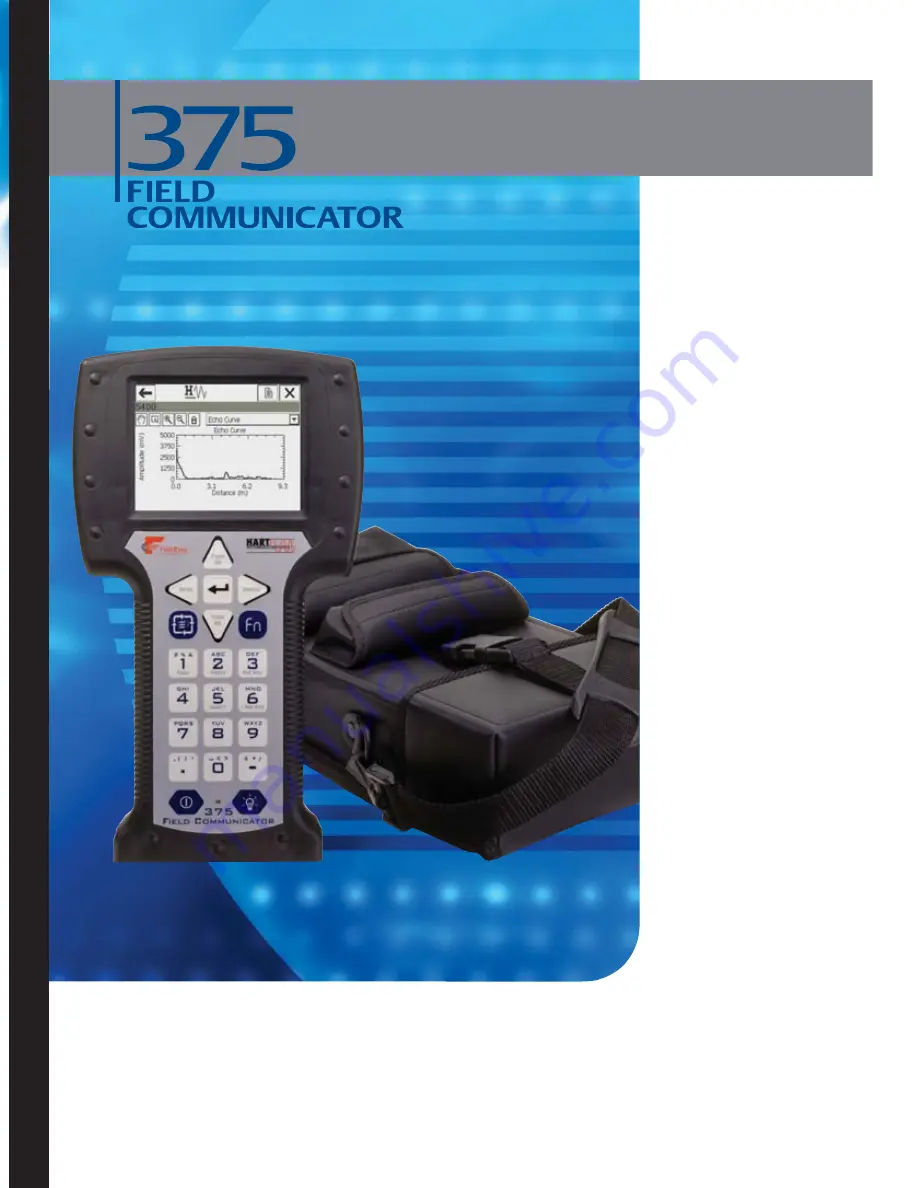
3
7
5
F
ield
Com
m
u
n
ic
a
tor
U
ser
’s M
an
u
a
l
Summary of Contents for Rosemount 375
Page 1: ...USER S MANUAL 375 Field Communicator User s Manual ...
Page 2: ......
Page 4: ......
Page 10: ...Introduction 1 2 ...
Page 40: ...Learning the Basics 2 30 ...
Page 112: ...Product Certifications B 8 ...
Page 113: ...Product Certifications B 9 ...
Page 114: ...Product Certifications B 10 ...
Page 132: ...G viii ...


