background image

Reference Manual

00809-0100-4308, Rev CD

February 2020

Rosemount

 3308 Series Wireless Guided

Wave Radar, 3308A

Summary of Contents for Rosemount 3308A

Page 1: ...Reference Manual 00809 0100 4308 Rev CD February 2020 Rosemount 3308 Series Wireless Guided Wave Radar 3308A ...

Page 2: ...event thermal electrical or mechanical damage Contacts should be protected to prevent premature discharge Battery hazards remain when cells are discharged Power modules should be stored in a clean and dry area For maximum battery life storage temperature should not exceed 86 F 30 C The power module may be replaced in a hazardous area The power module has surface resistivity greater than one gigaoh...

Page 3: ...in operation If the process seal is damaged gas could escape from the tank when removing the transmitter head from the probe Failure to follow these installation guidelines could result in death or serious injury Verify that the operating atmosphere of the transmitter is consistent with the appropriate hazardous locations certifications Ensure the transmitter is installed by qualified personnel an...

Page 4: ...odule The Power Module may be damaged if dropped from heights in excess of 20 ft 6 m Changes or modifications to the equipment not expressly approved by Rosemount Inc could void the user s authority to operate the equipment CAUTION The products described in this document are NOT designed for nuclear qualified applications Using non nuclear qualified products in applications that require nuclear qu...

Page 5: ...5 Centering disc for pipe installations 39 3 6 Anchor the probe 44 3 7 Mount device on tank 47 3 8 Ground the device 69 3 9 Install the power module 70 3 10 Position the antenna 71 3 11 Utilize the device display 72 Chapter 4 Configuration 75 4 1 Overview 75 4 2 Safety messages 75 4 3 Configuration procedure 77 4 4 System readiness 77 4 5 Get started with your preferred configuration tool 78 4 6 J...

Page 6: ... Appendix B Product Certifications 187 B 1 European directive information 187 B 2 Ordinary location certification 187 B 3 Telecommunication compliance 187 B 4 FCC and IC 187 B 5 Installing equipment in North America 188 B 6 USA 188 B 7 Canada 189 B 8 Europe 189 B 9 International 190 B 10 Brazil 191 B 11 China 191 B 12 Japan 191 B 13 Technical Regulations Customs Union EAC 191 B 14 Approval drawing...

Page 7: ... of the Device Descriptor DD 201 D 2 Configuration parameters 202 Appendix E Alert message mapping 223 E 1 Alert messages and descriptions 223 Reference Manual Contents 00809 0100 4308 February 2020 Reference Manual vii ...

Page 8: ...Contents Reference Manual February 2020 00809 0100 4308 viii Rosemount 3308 Series ...

Page 9: ... as well as diagnostic and error messages and service instructions Specifications and reference data supplies reference and specification data as well as ordering information Product Certifications contains hazardous locations certifications and approval drawings High gain remote antenna option contains specification and installation information of the high gain remote antenna option Configuration...

Page 10: ...Introduction Reference Manual February 2020 00809 0100 4308 10 Rosemount 3308 Series ...

Page 11: ...nergy is reflected back to the transmitter and the time difference between the generated and reflected pulse is converted into a distance from which the total level or interface level is calculated see Figure 2 1 Figure 2 1 Guided Wave Radar Operating Principle K A Reference peak B Product surface peak C Product level D Interface peak E Interface level F Upper reference point G Probe length H Tank...

Page 12: ...ansition between transmitter and the tank vapor space or air It is used by the transmitter as a starting reference point for distance to the level surface 2 1 2 Product surface peak This peak indicates the product level and is caused by a reflection from the product surface 2 1 3 Interface peak This peak indicates the interface level The peak is caused by reflection from the interface between an u...

Page 13: ... G C Flange D Tri Clamp E Upper Reference Point F Total Probe Length 2 1 6 Zero reference point The Zero Reference Point is selected by the user and is usually located close to or at the bottom of the tank The Zero Reference Point can be set to any position in the tank by adjusting the Tank Height 2 1 7 Tank height The Tank Height is the distance from the Upper Reference Point to the Zero Referenc...

Page 14: ...sible Measurements close to the Blind Zones will have reduced accuracy Figure 2 4 illustrates how the measuring range is related to the Blind Zones and the areas with reduced accuracy Figure 2 4 Blind Zones and Areas with Reduced Accuracy A Upper Blind Zone B Reduced accuracy C Recommended measuring range D Lower Blind Zone Note Measurements may not be possible in the Blind Zones and measurements ...

Page 15: ...plementing industry standard Encryption Authentication Verification Anti Jamming and Key Management ensures that data transmissions are secure and received only by the Gateway The Rosemount 3308 Series is a member of the Emerson Wireless portfolio whose wireless network experience totals billions of operating hours hundreds of thousands of field devices and tens of thousands of networks around the...

Page 16: ... are the preferred choice in almost all applications but depending on the application and installation geometries a coaxial probe or a twin probe may be a better fit For measuring the interface level the transmitter uses the residual wave of the first reflection Part of the wave which was not reflected at the upper product surface continues until it is reflected at the lower product surface The sp...

Page 17: ...le solution that is virtually unaffected by process conditions such as temperature pressure vapor gas mixtures density turbulence bubbling boiling varying dielectric media pH and viscosity Storage and buffer tanks The Rosemount 3308 Series Transmitter is ideal for storage or buffer tanks for almost any liquid such as oil gas condensate water or chemicals Low pressure separators The Rosemount 3308 ...

Page 18: ...eries transmitter housing contains advanced electronics for signal processing The transmitter housing is made of aluminum or stainless steel depending on specified option code The radar electronics produces an electromagnetic pulse which is guided by the probe There are different probe types available for various applications flexible single lead rigid single lead segmented rigid single lead flexi...

Page 19: ...D Dual compartment housing E Threaded process connections F BSPP G G NPT H Flexible single lead with weight I Rigid single lead J Flexible twin lead with weight K Coaxial L Segmented rigid single lead probe Reference Manual Transmitter overview 00809 0100 4308 February 2020 Reference Manual 19 ...

Page 20: ...anging density G G G G Changing dielectric 2 G G G G Wide pH variations G G G G Pressure changes G G G G Temperature changes G G G G Condensing vapors G G G G Bubbling boiling surfaces G G G G Foam mechanical avoidance NR NR NR AD Foam top of foam measurement AD AD AD NR Foam foam and liquid measurement AD AD AD NR Clean liquids G G G G Liquid with dielectric 2 0 3 AD AD AD AD Coating liquids 4 G ...

Page 21: ...AD 5 G AD 5 G Turbulent conditions causing breaking forces AD NR AD NR Non metallic tanks or open atmosphere applications AD 6 AD 6 AD 6 G 1 Not in fully submerged applications 2 For overall level applications a changing dielectric has no effect on the measurement For interface measurements a changing dielectric of the top fluid will degrade the accuracy of the interface measurement 3 See Table A ...

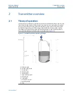
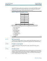
Page 22: ...Transmitter overview Reference Manual February 2020 00809 0100 4308 22 Rosemount 3308 Series ...

Page 23: ...n of device in an explosive environment must be in accordance with appropriate local national and international standards codes and practices Ensure device is installed in accordance with intrinsically safe or non incendive field practices Electrical shock could cause death or serious injury Ground device on non metallic tanks e g fiberglass tanks to prevent electrostatic charge build up Single le...

Page 24: ...nt a centering disc for pipe installations d Optional Anchor the probe 3 Mount device on tank 4 Ground the device 5 Install the power module 6 Position the antenna 7 Utilize the display 3 3 Review mounting considerations Before installing the Rosemount 3308 Series Transmitter consider recommendations for sufficient free space mounting position and special needs for non metallic tanks 3 3 1 Recomme...

Page 25: ...be anchored Avoid mounting close to heating coils Position the probe such that it is subject to a minimum of lateral force The probe should not come into contact with the nozzle or other objects in the tank Note Violent fluid movements causing high sideway forces may break rigid probes 3 3 2 Free space requirement If the probe is mounted close to a wall nozzle or other tank obstruction noise might...

Page 26: ...bing objects such as pipes and beams Plastic concrete or rugged metal tank wall 16 in 400 mm Flexible single Smooth metal tank wall 4 in 100 mm Disturbing objects such as pipes and beams Plastic concrete or rugged metal tank wall 16 in 400 mm Coaxial 1 N A 0 in 0 mm Flexible twin N A 4 in 100 mm 1 Minimum clearance from tank bottom for the coaxial and rigid single probes is 0 2 in 5 mm Installatio...

Page 27: ...zle diameter 4 in 100 mm or more 4 in 100 mm or more 4 in 100 mm or more probe diameter Minimum nozzle diameter 1 1 5 in 38 mm 1 5 in 38 mm for probe type 4A 2 in 50 mm for probe type 4B and 4S 2 in 50 mm probe diameter Maximum nozzle height 2 4 in 100 mm nozzle diameter 3 4 in 100 mm nozzle diameter 4 in 100 mm nozzle diameter N A 1 The Trim Near Zone TNZ function may be necessary or an Upper Nul...

Page 28: ... mm Flexible single 4 in 100 mm Consult your local Emerson representative Flexible twin 1 4 in 100 mm Consult your local Emerson representative Coaxial 3 or 4 in 75 or 100 mm 1 5 in 37 5 mm 1 The center rod must be placed more than 0 6 in 15 mm away from the pipe wall Note Metal pipes are preferred especially in applications with low dielectric constant to avoid disturbances from objects near the ...

Page 29: ...rs Chamber type Probe length Side to side chamber A CC B 80 mm Side to bottom chamber A CC 80 mm Use a centering disc the same diameter as the chamber if the probe length 3 3 ft 1 m See Table 3 8 for which disc to use Existing chamber A Rosemount 3308 Series Transmitter is the perfect replacement in an existing displacer chamber Proprietary flanges are offered enabling use of existing chambers to ...

Page 30: ...ted proprietary flange Displacer 8 in 203 mm Other torque tube 2 Displacer 8 in 203 mm Magnetrol spring operated 3 Displacer between 7 8 in 195 mm to 15 in 383 mm Others spring operated 2 Displacer 19 7 in 500 mm 1 If flushing ring is used add the ring height to the probe length 2 For other manufacturers there are small variations This is an approximate value actual length should be verified 3 Len...

Page 31: ...stallation in non metallic tanks and open air applications Avoid major sources of electrical disturbance in proximity of the installation e g electrical motors stirrers servo mechanisms Figure 3 6 Avoid Electromagnetic Disturbances For clean liquids use a coaxial probe to reduce effect of potential electrical disturbances Figure 3 7 Coaxial Probe in an Open Air Application For optimal single lead ...

Page 32: ...alk Table 3 6 provides recommended minimum distance between two probes A coaxial probe or a probe installed in a still pipe will not cause any cross talk Table 3 6 Minimum Distance between Single Probes Product Minimum distance between probes Oil DC 2 1 5 2 ft 1 6 m Water DC 80 3 3 ft 1 0 m 3 4 Review mounting preparations 3 4 1 Measure tank height The Tank Height is defined as the measured distan...

Page 33: ...ned The goal is to have the probe hang straight so that it does not touch the wall 2 in 5 cm is a suggested value The probe can be shortened in field Use the following form to calculate the probe length Probe length tank height 2 in 5 cm After shortening the probe make sure to update the transmitter configuration to the new probe length see Probe length Reference Manual Installation 00809 0100 430...

Page 34: ...clearance Shorten the flexible single twin lead probe Prerequisites Note The PTFE covered probes must not be cut in field Procedure 1 Mark where to cut the probe 1 2 3 4 5 6 7 8 0 Installation Reference Manual February 2020 00809 0100 4308 34 Rosemount 3308 Series ...

Page 35: ...Remove enough spacers to make place for the weight only flexible twin lead probes 3 Loosen the weight 4 Slide the weight up Reference Manual Installation 00809 0100 4308 February 2020 Reference Manual 35 ...

Page 36: ...uisites After shortening the probe be sure to update the transmitter configuration to the new probe length Related information Probe length Shorten the rigid single lead probe Prerequisites The minimum probe length is 15 7 in 400 mm Note The PTFE covered probes must not be cut in field Installation Reference Manual February 2020 00809 0100 4308 36 Rosemount 3308 Series ...

Page 37: ... probe 1 2 3 4 5 6 7 8 0 2 Cut the probe at the mark Postrequisites After shortening the probe be sure to update the transmitter configuration to the new probe length Related information Probe length Reference Manual Installation 00809 0100 4308 February 2020 Reference Manual 37 ...

Page 38: ...ortening length 23 6 in 600 mm D Minimum probe length 15 7 in 400 mm Procedure 1 Mark where to cut the probe Pipes longer than 49 in 1250 mm can be shortened by as much as 23 6 in 600 mm Pipes shorter than 49 in 1250 mm can be cut as long as the remaining length is not less than 15 7 in 400 mm Installation Reference Manual February 2020 00809 0100 4308 38 Rosemount 3308 Series ...

Page 39: ... 3 5 Centering disc for pipe installations To prevent the probe from contacting the chamber or pipe wall centering discs are available for flexible single rigid single and flexible twin lead probes The disc is attached to the end of the probe Discs are made of stainless steel Alloy C 276 Duplex 2205 or PTFE For the segmented rigid single lead probe up to five PTFE centering discs can be mounted al...

Page 40: ... 68 mm 4 in 3 6 in 92 mm 6 in 5 55 in 141 mm 8 in 7 40 in 188 mm Table 3 8 Centering Disc Size Recommendation for Different Pipe Schedules Pipe size Pipe schedule 5s 5 and 10s 10 40s 40 and 80s 80 120 160 2 in 2 in 2 in N A 1 N A 2 3 in 3 in 3 in N A 1 2 in 4 in 4 in 4 in 4 in 3 in 5 in 4 in 4 in 4 in 4 in 6 in 6 in 6 in 4 in 4 in 7 in N A 1 6 in N A 1 N A 1 8 in 8 in 8 in 6 in 6 in 1 Schedule is ...

Page 41: ...tering disc at the end of the weight 13 mm 2 Secure the bolt by folding the tab washer 3 5 2 Mount a centering disc on rigid single lead probe 8 mm Note Centering discs shall not be used with PTFE covered probes Reference Manual Installation 00809 0100 4308 February 2020 Reference Manual 41 ...

Page 42: ...ing disc and washer at the probe end Note Do not mount the washer A if the centering disc material is PTFE Alloy C 276 Duplex 2205 or Alloy 400 3 Insert the split pin through the bushing and the probe 4 Secure the split pin Installation Reference Manual February 2020 00809 0100 4308 42 Rosemount 3308 Series ...

Page 43: ...oles using the drilling fixture included in your shipment 2 Mount the bushings and centering disc at the probe end 3 Adjust distance by shifting hole for split pin in lower bushing 0 16 in 4 mm 0 08 in 2 mm Reference Manual Installation 00809 0100 4308 February 2020 Reference Manual 43 ...

Page 44: ...be itself can be used for anchoring Pull the probe rope through a suitable anchoring point e g a welded eye and fasten it with a chuck Table 3 9 Required Torque and Hex Key Dimensions Probe Required torque Hex key dimension Flexible twin lead 4 4 ft lb 6 Nm 4 mm Flexible single lead 4 mm wire stainless steel 3 7 ft lb 5 Nm 4 mm 4 mm wire Alloy C 276 1 8 ft lb 2 5 Nm 3 mm 4 mm wire Alloy 400 1 8 ft...

Page 45: ...le at the end of the weight Attach the ring to a suitable anchoring point Figure 3 14 Flexible Twin Single Lead Probe with Weight and Ring A Weight with internal threads M8x14 B Ring A magnet customer supplied can be fastened in a threaded M8x14 hole at the end of the weight The probe can then be guided by placing a suitable metal plate beneath the magnet Reference Manual Installation 00809 0100 4...

Page 46: ...handle thermal expansion The measurement accuracy will be reduced close to the tube opening Figure 3 16 Rigid Single Lead Probe with Tube A Drain Coaxial probe The coaxial probe can be secured to the tank wall by fixtures fastened to the tank wall Fixtures are customer supplied Ensure the probe can move freely due to thermal expansion without getting stuck in the fixture Installation Reference Man...

Page 47: ...acy will be reduced close to the tube opening Figure 3 18 Coaxial Probe with Tube A Drain 3 7 Mount device on tank Mount the transmitter with flange on a nozzle on top of the tank The transmitter can also be mounted on a threaded or Tri Clamp connection 3 7 1 Threaded tank connection Prerequisites Note PTFE covered probes must be handled carefully to prevent damage to the coating Reference Manual ...

Page 48: ...asket on top of the tank flange 2 For adapters with NPT threads use anti seize paste or PTFE tape according to your site procedures 3 Lower the transmitter and probe into the tank Installation Reference Manual February 2020 00809 0100 4308 48 Rosemount 3308 Series ...

Page 49: ...ly 60 mm 5 Screw the adapter into the process connection 52 mm 60 mm 6 Rotate the transmitter head so the device display faces the desired direction 7 Tighten the nut 60 mm Torque 30 Lbft 40 Nm Reference Manual Installation 00809 0100 4308 February 2020 Reference Manual 49 ...

Page 50: ...event damage to the coating Procedure 1 Place a suitable gasket on top of the tank flange Note Gasket should not be used for PTFE covered probe with protective plate A PTFE covered probe with protective plate 2 Lower the transmitter and probe with flange into the tank Installation Reference Manual February 2020 00809 0100 4308 50 Rosemount 3308 Series ...

Page 51: ...nge and gasket choice 4 Loosen the nut that connects the transmitter head to the probe slightly 60 mm 5 Rotate the transmitter head so the device display faces the desired direction Reference Manual Installation 00809 0100 4308 February 2020 Reference Manual 51 ...

Page 52: ...to one unit If for some reason these parts have been disassembled mount the transmitter as described below Prerequisites Note PTFE covered probes must be handled carefully to prevent damage to the coating Procedure 1 Mount the flange on the probe and tighten the flange nut 60 mm 2 Place a suitable gasket on top of the tank flange Installation Reference Manual February 2020 00809 0100 4308 52 Rosem...

Page 53: ... bolts and nuts with sufficient torque for the flange and gasket choice 5 Mount the transmitter head 60 mm Torque 30 Lbft 40 Nm Postrequisites Continue with the grounding step Reference Manual Installation 00809 0100 4308 February 2020 Reference Manual 53 ...

Page 54: ...pe B Vertical pipe On wall 4X 2 Mount the transmitter with probe to the bracket 3X 3 7 5 Tank connection with Tri Clamp Prerequisites Note PTFE covered probes must be handled carefully to prevent damage to the coating Installation Reference Manual February 2020 00809 0100 4308 54 Rosemount 3308 Series ...

Page 55: ...smitter and probe into the tank 3 Tighten the clamp to the recommended torque see the manufacturer s instruction manual 4 Loosen the nut that connects the transmitter head to the probe slightly 60 mm Reference Manual Installation 00809 0100 4308 February 2020 Reference Manual 55 ...

Page 56: ...d so the device display faces the desired direction 6 Tighten the nut 60 mm Torque 30 Lbft 40 Nm Postrequisites Continue with the grounding step Installation Reference Manual February 2020 00809 0100 4308 56 Rosemount 3308 Series ...

Page 57: ...t H Bottom segment length varies depending on total probe length I Bushing for the centering disc at the probe end J Bottom centering disc in PTFE or stainless steel optional Verifying probe length Segmented probe ordered with model code 4S Before installation verify the probe length L on the label If the probe length needs to be adjusted see Adjust the probe length Reference Manual Installation 0...

Page 58: ...the desired probe length must be determined Also the bottom segment may need to be shortened See Adjust the probe length Assemble the segmented probe Prerequisites Note If there is enough space beside the tank the probe can be assembled before inserting it into the tank Installation Reference Manual February 2020 00809 0100 4308 58 Rosemount 3308 Series ...

Page 59: ...cedure 1 Insert the stop screw to the top segment Tighten approximately two turns 7RS 6HJPHQW 2 Pre assemble the safety ring Reference Manual Installation 00809 0100 4308 February 2020 Reference Manual 59 ...

Page 60: ...l If ordered mount the centering disc on the bottom segment of the probe RWWRP 6HJPHQW 4 Insert the support tool RWWRP 6HJPHQW Installation Reference Manual February 2020 00809 0100 4308 60 Rosemount 3308 Series ...

Page 61: ...dered mount the centering disc Maximum five pcs probe Minimum two segments between each centering disc 6 Mount a middle segment hand tight Reference Manual Installation 00809 0100 4308 February 2020 Reference Manual 61 ...

Page 62: ...7 Secure the split pin 8 Insert the second support tool Installation Reference Manual February 2020 00809 0100 4308 62 Rosemount 3308 Series ...

Page 63: ...til all segments are mounted Be sure to finish with the top segment of the probe 11 Seal and protect threads Use anti seize paste or PTFE tape according to your site procedures Only for NPT threaded tank connection Reference Manual Installation 00809 0100 4308 February 2020 Reference Manual 63 ...

Page 64: ...ople are needed when mounting the device Hold the device above the tank High loads can break the support tool A Flange Tri Clamp B Threaded C Gasket D Sealant on threads NPT E Gasket BSPP G Installation Reference Manual February 2020 00809 0100 4308 64 Rosemount 3308 Series ...

Page 65: ...13 Tighten the stop screw and slide the safety ring into the groove 14 Remove the support tool Reference Manual Installation 00809 0100 4308 February 2020 Reference Manual 65 ...

Page 66: ...ge B Tri Clamp C Threaded 16 Rotate the housing to the desired direction 17 Tighten the nut Torque 30 Lbft 40 Nm 60 mm 18 Continue with the grounding step Installation Reference Manual February 2020 00809 0100 4308 66 Rosemount 3308 Series ...

Page 67: ...e Y the length of the bottom segment See Table 3 10 Y length of bottom segment 4 Continue as follows Length of bottom segment Y Action Y 0 4 in 10 mm Continue with step 7 Do not use the bottom segment Y 0 4 in 10 mm Continue with step 5 and cut the bottom segment Y 31 5 in 800 mm a Add one extra middle segment to the calculated n b Continue with step 7 Reference Manual Installation 00809 0100 4308...

Page 68: ... the bottom segment 1 2 3 4 5 6 7 8 0 1 2 3 0 6 Cut the bottom segment at the mark Note Ensure the bottom segment is fixed while cutting Installation Reference Manual February 2020 00809 0100 4308 68 Rosemount 3308 Series ...

Page 69: ... 6800 L 7600 8 pcs Y L 267 7 Y L 6800 299 2 L 330 7 7600 L 8400 9 pcs Y L 299 2 Y L 7600 330 7 L 362 2 8400 L 9200 10 pcs Y L 330 7 Y L 8400 362 2 L 393 7 9200 L 10000 11 pcs Y L 362 2 Y L 9200 3 8 Ground the device The Rosemount 3308 Series Wireless Guided Wave Radar transmitter operates with the housing grounded or floating Floating systems can cause extra noise that may affect many types of rea...

Page 70: ...e or coaxial probe are the recommended choice for non metallic tanks Single lead probes are not suited for non metallic tanks or open atmosphere applications due to high susceptibility to strong electromagnetic fields 3 9 Install the power module Prerequisites CAUTION Use caution when handling the power module it may be damaged if dropped from heights in excess of 20 ft 6 m Installation Reference ...

Page 71: ...lectronics housing covers so that metal touches metal but do not overtighten A Keep cover tight 3 10 Position the antenna The antenna should be positioned vertically either straight up or straight down and it should be approximately 3 ft 1 m from any large structure building or conductive surface to allow for clear communication to other devices Reference Manual Installation 00809 0100 4308 Februa...

Page 72: ...queeze the two black tabs on opposite sides of the display Refer to Figure 3 23 2 Gently pull out the display 3 Rotate the display to the desired orientation and snap the display into place Figure 3 23 Device Display A Display pins B Black tabs C Display D Cover Note If the device display four pin connector is inadvertently removed from the interface board carefully reinsert the connector before s...

Page 73: ...it number 00753 9004 0001 aluminum display kit or 00753 9004 0004 stainless steel display kit These kits contain an extended cover with a display viewing window a display board and a display pin connector Replace the flat cover with the extended display and tighten Reference Manual Installation 00809 0100 4308 February 2020 Reference Manual 73 ...

Page 74: ...Installation Reference Manual February 2020 00809 0100 4308 74 Rosemount 3308 Series ...

Page 75: ...nfiguration tool Configuration parameters provides extended information about the configuration parameters An overview of Device Descriptor DD menu is presented in Menu overview of the Device Descriptor DD All configuration parameters are described in Configuration parameters 4 2 Safety messages Instructions and procedures in this section may require special precautions to ensure the safety of the...

Page 76: ...trostatic charge build up Process leaks could result in death or serious injury Only qualified personnel should install the equipment Handle the transmitter carefully If the process seal is damaged gas could escape from the tank when removing the transmitter head from the probe To ensure long life for your radar transmitter and to comply with hazardous location installation requirements tighten co...

Page 77: ... Network 3 Configure device a Connect to device b Configure using basic setup c Consider optional setup 4 Verify level 4 4 System readiness 4 4 1 Confirm correct device driver Verify the latest Device Descriptor DD is loaded on your systems to ensure proper communication Procedure 1 Within Table 4 1 use the HART Universal Revision and Device Revision numbers to find the correct DD 2 Download the l...

Page 78: ...reserved and product can be used interchangeably 2 HART software revision can be read using a HART capable configuration tool select Overview Device Information Revisions 4 5 Get started with your preferred configuration tool 4 5 1 AMS Wireless Configurator version 12 0 or later is required The AMS Wireless Configurator is the recommended software tool for the wireless network devices and is suppl...

Page 79: ...gh the configuration Prerequisites The Rosemount 3308 Series DD is typically installed together with AMS Wireless Configurator To download the latest HART DD visit the Emerson Device Install Kit site at Emerson com DeviceInstallKits Procedure After downloading add the DD to AMS Wireless Configurator a Close AMS Wireless Configurator b Go to Start Programs AMS Device Manager and select Add Device T...

Page 80: ...rface Before connecting to the device wirelessly using a Wireless Gateway the wireless network must be configured in AMS Wireless Configurator Procedure 1 Close AMS Wireless Configurator 2 Go to Start Programs AMS Device Manager and select Network Configuration 3 Select Add 4 In the drop down list select Wireless Network and then select Install 5 Follow the on screen instructions Need help In the ...

Page 81: ...alled and functioning properly before any wireless field devices are powered Wireless devices should be powered up in order of proximity from the Gateway beginning with the closest This will result in a simpler and faster network installation Procedure 1 Install the power module 2 Enable Active Advertising on the Gateway to ensure that new devices join the network faster For more information see t...

Page 82: ...his screen will not display if all characters are blank 4 Software revision Used to determine device software revision 5 Device information Status This screen will only appear if there is a critical error which may prevent the device from operating correctly Check additional status screens for more information about failure source refer to Table 5 1 6 Primary variable Measurement value of mapped p...

Page 83: ...in percent of total measurement range 11 Active alert present This screen will only appear if there is at least one active alert present For detailed information of the failure source and recommended actions go to the Active Alerts screen in AMS Wireless Configurator or the handheld communicator Refer to Check device status Some active alerts will be displayed on the LCD display as part of the dia...

Page 84: ...he handheld communicator and connect to the device Figure 4 4 Connect to Device 1 2 3 4 5 6 7 8 0 9 A Communication terminals B Handheld communicator C HART modem Related information AMS Wireless Configurator version 12 0 or later is required Handheld communicator 4 6 3 Configure update rate The Update Rate is the frequency at which a new measurement is transmitted over the wireless network The de...

Page 85: ...pdate is too long the high low alerts may be triggered too late Postrequisites Run Check Level Response to make sure that configured Update Rate is sufficient for the application Related information Consider optional setup 4 6 4 Obtain network ID and join key In order to communicate with the Wireless Gateway and ultimately the host system the transmitter must be configured to communicate on the wi...

Page 86: ...elect Configure Guided Setup Wireless Setup 2 Select Join Device to Network and follow the instructions Postrequisites If the device is not to be commissioned yet remove the power module and fasten the housing cover This is to conserve power module life and to ensure safe transmitter transportation The power module should be inserted only when the device is ready to be commissioned 4 6 6 Verify de...

Page 87: ... 1 Unscrew the device display cover 2 Press the DIAG button The display will show Tag Device Serial Number Software Revision Network ID Network Connection Status and Device Status screens Refer to Table 5 1 When the network diagnostic status is displayed as NETWK OK the device has successfully joined the network When joining the wireless network the status displayed will be changed through the seq...

Page 88: ...d Network Idle The device is starting to join the process Disconnected from Network The device is in a disconnected state and requires a Force Join command to join the network Searching for Network The device is searching for the network Joining the Network The device is attempting to join the network Configuration Reference Manual February 2020 00809 0100 4308 88 Rosemount 3308 Series ...

Page 89: ...is connected to the network but is in a quarantined state Connected with Limited Bandwidth The device is joined and operational but is running with limited bandwidth for sending periodic data Connected The device has successfully joined the network Reference Manual Configuration 00809 0100 4308 February 2020 Reference Manual 89 ...

Page 90: ...nnection Status Images Not Connected Searching Joining Limited Bandwidth Connected Verify by Gateway Procedure 1 To use the Wireless Gateway s integrated web interface navigate to the Explorer Status page as shown in Figure 4 8 This page shows whether the device has joined the network and if it is communicating properly 2 Locate the device in question and verify all status indicators are good gree...

Page 91: ...the power module Procedure 1 Connect the handheld communicator as shown in Figure 4 4 2 Select Service Tools Communications 3 Select Join Status 4 7 Configure device using guided setup 4 7 1 Connect to device Procedure 1 Connect to the device using your preferred configuration tool as shown in Figure 4 9 and Figure 4 10 2 Do one of the following AMS Wireless Configurator a Start AMS Wireless Confi...

Page 92: ...evice Figure 4 9 Connect to Device 1 2 3 4 5 6 7 8 0 9 A Communication terminals B Handheld communicator C HART modem Figure 4 10 Connect to Device Wirelessly A Wireless Gateway 4 7 2 Configure using basic setup Procedure 1 Select Configure 2 Select Guided Setup Initial Setup Configuration Reference Manual February 2020 00809 0100 4308 92 Rosemount 3308 Series ...

Page 93: ...n the Guided Setup Run Check Level Response to review the maximum level change between updates with the current configuration Procedure 1 Select Configure 2 Select Guided Setup Optional Setup 3 Select the desired Optional Setup and follow the instructions Additional configuration parameters are available in the Manual Setup menu Related information Configuration parameters Reference Manual Configu...

Page 94: ... vessels and installation geometry may introduce an offset for the Upper Reference Point This offset may be up to 2 in 50 mm The offset can be compensated for by using Calibration Offset 4 8 1 Run verify level Run the Verify Level tool to match the product level reported by the device to a reference measurement measured by using for example handgauging Prerequisites Note Before running Verify Leve...

Page 95: ...4 Follow the on screen instructions Reference Manual Configuration 00809 0100 4308 February 2020 Reference Manual 95 ...

Page 96: ...Configuration Reference Manual February 2020 00809 0100 4308 96 Rosemount 3308 Series ...

Page 97: ...ance with intrinsically safe or non incendive field practices Electrical shock could cause death or serious injury Ground device on non metallic tanks e g fiberglass tanks to prevent electrostatic charge build up Single lead probes are sensitive for strong electromagnetic fields and therefore not suitable for non metallic tanks Care must be taken during transportation of power module to prevent el...

Page 98: ...display screen messages The device display can be used to present different variables and a diagnostic screen sequence 5 2 1 Variable screens If the Display Mode is set to Periodic the device display shows a periodic sequence of user chosen variables during operation A new screen appears according to configured wireless update rate The device display will also show ALERT PRESNT if at least one ale...

Page 99: ...formation Device display 5 2 2 View diagnostic screens The diagnostic button screen sequence on the device display can be used to obtain detailed diagnostic information Procedure 1 Unscrew the device display cover Reference Manual Operation 00809 0100 4308 February 2020 Reference Manual 99 ...

Page 100: ...stic button screen sequence Table 5 1 Diagnostic Button Screen Sequence Screen Sequence Description 1 Device Information Tag User entered tag which is 8 characters long This screen will not display if all characters are blank 2 Device Serial Number Used to determine Device Serial Number 3 Software Revision Used to determine Device Software Revision Operation Reference Manual February 2020 00809 01...

Page 101: ...ear on this position of the sequence 7 Variable Screens At the end of the sequence the device display shows all selected variable screens 8 Active Alert Present This screen will only appear if there is at least one Active Alert present For detailed information of the failure source and recommended actions go to the Active Alerts screen in AMS Wireless Configurator or handheld communicator Refer to...

Page 102: ... log measurement values either in a graph or a table To log Level and Interface Level values in a graph select Level To log Distance values in a graph select Distance To log Total Volume in a graph select Volume To log Signal Quality in a graph select Signal Quality To log the trend of 12 data points shown in a table select Data History and then select View Data History Note Values are logged in t...

Page 103: ...rview screen to view the overall device status 2 If status is anything other than Good select the button in the device status image to open a window with Active Alerts The different device status images can be found in Table 5 2 Active Alerts can also be obtained via Service Tools Alerts Active Alerts Table 5 2 Presentation of Device Status Images Device status image Category Condition Action Good...

Page 104: ...Status Images continued Device status image Category Condition Action Advisory At least one Advisory Alert is active and no Failed or Maintenance Alerts Operation Reference Manual February 2020 00809 0100 4308 104 Rosemount 3308 Series ...

Page 105: ...uild up Single lead probes are sensitive for strong electromagnetic fields and therefore not suitable for non metallic tanks Care must be taken during transportation of power module to prevent electrostatic charge build up Probes covered with plastic and or with plastic discs may generate an ignition capable level of electrostatic charge under certain extreme conditions Therefore when the probe is...

Page 106: ...lowed under any circumstances CAUTION Use caution when handling the power module The Power Module may be damaged if dropped from heights in excess of 20 ft 6 m This device complies with Part 15 of the FCC Rules Operation is subject to the following conditions This device must accept any interference received including interference that may cause undesired operation This device must be installed to...

Page 107: ...ice may be affected Configuration Failure The device has detected a configuration error Critical operation of the device may be affected Electronics Warning There is a warning which should be addressed but should not affect the device output Electronics Failure An electronics error that could impact the device measurement reading has occurred Radio Failure The wireless radio has detected a failure...

Page 108: ...will affect device operation Replace the Power Module see Replace power module For detailed information of the failure source and recommended actions go to the Active Alerts screen in AMS Wireless Configurator or the handheld communicator Related information Alert messages in AMS Wireless Configurator and handheld communicator 6 2 2 Alert messages in AMS Wireless Configurator and handheld communic...

Page 109: ...he internal temperature of the device has reached critical levels and the integrity of the device electronics may be compromised Environmental temperature should not exceed device specifications 1 Verify that ambient temperature is within the specified range For more information about the maximum ambient temperature see Temperature limits 2 Remote mount the transmitter head away from the process a...

Page 110: ...e configuration values in a set that belongs together has been changed and reduced the measurement range of the device 1 Check the configured values for Probe Length Vapor Dielectric Constant and Upper Product Dielectric Constant 2 Restore default settings and reconfigure the device Low Low Level Alert configuration is invalid Low Low Level Alerts will not be raised as expected because of invalid ...

Page 111: ... power module Electronics Temperature Out of Limits The temperature of the electronics board has exceeded the transmitter s operating range 1 Verify that ambient temperature is within the operating range 2 Restart the device 3 Remote mount the transmitter head away from the process and environmental conditions 4 If the condition persists replace the device Level Measurement Lost No valid Level rea...

Page 112: ...is alert 2 Clean the probe 3 If no actions were necessary consider to change the limit Capacity Denied The device has failed to acquire the wireless communication bandwidth necessary to support the configured update rates 1 Obtaining the bandwidth may take some time depending on the configured update rates and other devices in the network Wait several minutes to see if the error resolves itself 2 ...

Page 113: ...vice 4 Restore default settings and reconfigure the device 5 If the condition persists replace the device Non Critical User Data Warning A user written parameter does not match expected value 1 Restart the device 2 Reconfirm all configuration items in the device 3 Restore default settings and reconfigure the device 4 If the condition persists replace the device Volume Range Warning The level measu...

Page 114: ...w the defined limit 1 Bring the system to a safe state 2 Verify that the level is within specified limits 3 Reconfirm the level alert limit 4 If not needed disable this alert User Defined Alert The variable has surpassed the user defined limit 1 Bring the system to a safe state 2 Verify that the process variable is within user specified limits 3 Reconfirm the user defined alarm limit 4 If not need...

Page 115: ...see Upper product dielectric constant The transmitter is configured with wrong Probe Type refer to Probe type Check Thresholds see Adjust thresholds The transmitter has locked on disturbing obstacles at top of the tank See Handling disturbances at the top of the tank for recommended actions The surface is turbulent Set the Performance Mode to High to get a stable measurement signal refer to Resolv...

Page 116: ...interface level reading Symptom Possible cause and recommended actions Incorrect Interface Level reading The Upper Product Dielectric Constant is not correct see Upper product dielectric constant Air gap is too big when the Measurement Mode is set to Interface Level with Submerged Probe Reduce air gap or switch the Measurement Mode to Product Level and Interface Level Missing Interface Level readi...

Page 117: ...Possible cause and recommended actions The Power Module seems to run out of battery very fast Consider Update Rate refer to Configure update rate Selecting a fast update rate has an impact on Power Module life Consider Performance Mode refer to Performance mode The Power Module life is reduced if Performance Mode is set to High Check that Power Mode is set to Normal see Power mode Verify device is...

Page 118: ...or Reduce the Update Rate on transmitter refer to Configure update rate Increase communication paths by adding more wireless points Check that device has been online for at least an hour Check that device is not routing through a limited routing node Create a new network with an additional Wireless Gateway 6 4 Service and troubleshooting tools This section briefly describes tools and functions in ...

Page 119: ...top of the tank the first echo found above the Surface Threshold is considered as the product surface as illustrated in Figure 6 2 Other pulses further away from the top although above the Surface Threshold are ignored When the surface echo is found the next pulse below the product surface and with a signal strength above the Interface Threshold is considered as the Interface By default the amplit...

Page 120: ... transmitter and no manual settings are needed However due to the properties of the product it may in rare cases be necessary to adjust the amplitude thresholds for optimum measurement performance Guidelines for setting the surface threshold Before changing the Surface Threshold ensure the product level is at least 20 in 0 5 m from the lower side of the device flange Surface Thresholds should neve...

Page 121: ...ce Threshold and the surface echo amplitude over the entire measuring range A Amplitude B Distance C Surface Threshold D Surface echo E At least 3 Cnts margin The Surface Threshold should be at least 3 Cnts greater than the amplitude of disturbances Reference Manual Service and troubleshooting 00809 0100 4308 February 2020 Reference Manual 121 ...

Page 122: ...ing the amplitude thresholds check that the Upper Product Dielectric Constant parameter is set as accurately as possible The Upper Product Dielectric Constant is used for setting the automatically calculated amplitude thresholds Procedure 1 Read the Echo Curve a Start the Echo Curve reading b View the Echo Curve plot and check the relation between amplitude threshold and corresponding signal ampli...

Page 123: ...ation like this the Surface Threshold has to be lowered so that the surface peak is not filtered out Figure 6 3 Surface Threshold Is Too High A Amplitude B Distance C Surface Threshold is above the Product Surface peak If there are disturbing objects in the tank the Surface Threshold must be carefully set to avoid locking on the wrong amplitude peak In Figure 6 4 the Surface Threshold is too low a...

Page 124: ...ted the product surface is correctly detected Example 2 Interface peak not found In interface applications where the bottom product has a relatively low dielectric constant 40 or if the signal is attenuated in the upper product the amplitude of the reflected signal from the interface is relatively low and difficult for the transmitter to detect In such a case it may be possible to detect the refle...

Page 125: ...reshold D Product Surface Peak E The Interface Threshold is above the Interface Peak By adjusting Interface Threshold the peak at the interface between the upper and lower products is detected as illustrated in Figure 6 7 Figure 6 7 After Changing the Interface Threshold the Transmitter Detects the Interface A Amplitude B Distance C Surface Threshold D After Interface Threshold is adjusted the int...

Page 126: ...n status and details View network join status Wireless devices join the network through a four step process Step 1 Network Found Step 2 Network Security Clearance Granted Step 3 Network Bandwidth Allocated Step 4 Network Join Complete To view the Network Join Status of the device Procedure Select Service Tools Communications Network Join Status Obtain network join details Obtain detailed informati...

Page 127: ...ed to join the network prior to being accepted Too many join attempts result in the device considering the join attempt as failed If this happens re check the Join Key and Network ID 6 4 5 Locate the device Use the Locate Device function to identify this device by showing a pattern on the device display as illustrated in Figure 6 8 Procedure 1 Select Service Tools Maintenance Routine Maintenance 2...

Page 128: ...hreshold Intersection Thin oil layer on top of water might cause jumpy surface readings Because of the thin oil layer the transmitter varies between detecting oil and water Sometimes the oil layer gets too thin to be detected see Figure 6 9 Figure 6 9 Thin Oil Layer on Top of Water Peak Detection Method Set to Peak Center A Oil peak detected as surface B Water peak C Surface Threshold D Too thin o...

Page 129: ...ced 2 Under Peak Detection Method select Threshold Intersection and then click Send 3 Run Verify Level to compensate for any offset error see Figure 6 11 introduced by the Threshold Intersection method Figure 6 11 Thin Oil Layer on Top of Water Peak Detection Method Set to Threshold Intersection A Surface detected at first intersection with Surface Threshold even when there is an oil peak B Actual...

Page 130: ...might need to manually set the Near Zone Threshold This may for example be the case if a Single Lead probe is mounted in a narrow nozzle if the end of the nozzle protrudes into the tank or if there are disturbing obstacles in the Near Zone referred to as the region between 0 3 3 ft 0 1 m below the Upper Reference Point Figure 6 12 Near Zone Threshold A Reference Peak B Disturbance C Product Surfac...

Page 131: ...The Threshold and End Distance values can now be changed d Under Threshold type the desired value into the box e Under End Distance type the desired value into the box This value is the distance from Upper Reference Point to point where the Near Zone Threshold ends Related information Read the echo curve Trim Near Zone function The Trim Near Zone function is used to fine tune performance in the ar...

Page 132: ...d for reducing impact from stationary disturbances For occasional disturbances use the Near Zone Threshold Procedure 1 Select Service Tools Echo Tuning and click Near Zone 2 Under Near Zone Compensation select Trim Near Zone and follow the on screen instructions Change the upper null zone Measurements are not performed within the Upper Null Zone UNZ The Upper Null Zone can be extended to block out...

Page 133: ...uring range must be below the Upper Null Zone Figure 6 15 Upper Null Zone A Upper Reference Point B Upper Null Zone C Measurement Range Note Before changing the Upper Null Zone check entered limit and deadband values for the High Level Alerts High Level Alerts should not be placed in the Upper Null Zone Reference Manual Service and troubleshooting 00809 0100 4308 February 2020 Reference Manual 133...

Page 134: ...merged Probe The measurement mode Interface Level with Submerged Probe is used to handle interface measurements when the product level is not visible for example in a full chamber pipe as illustrated in Figure 6 16 In this case the probe is fully submerged into the upper product and only the interface level is detected by the transmitter Figure 6 16 Interface Level Measurements in a Full Chamber U...

Page 135: ... Note Adjust Interface Threshold if the interface level pulse is not detected 6 5 4 Resolve noise or weak surface echoes In difficult applications where the surface echo peak is low compared to the noise it is recommended to set the Performance Mode to High Performance A low surface peak compared to the noise might be caused by a turbulent surface foam low dielectric constant plastic tanks and so ...

Page 136: ... as the batteries and the battery pack integrity are maintained Care should be taken to prevent thermal electrical or mechanical damage Contacts should be protected to prevent premature discharge Use caution when handling the power module It may be damaged if dropped from heights in excess of 20 ft 6 m Battery hazards remain when cells are discharged 6 6 2 Environmental considerations As with any ...

Page 137: ... before shipping 6 7 Replace the transmitter head Prerequisites Note If the transmitter head must be removed from the probe ensure that the process seal is carefully protected from dust and water Figure 6 18 Transmitter Head Replacement A Flanged version B Nut C Process seal D Put the protection plug here E Threaded version F Adapter Procedure 1 Loosen the nut that connects the transmitter head to...

Page 138: ... the protection plug to the process seal to protect the exposed parts from dust and water If a protection plug is not available then cover the process seal with a plastic bag 6 Rotate the new transmitter head so the device display faces the desired direction 7 Tighten the nut Max torque is 30 ft lb 40 Nm Postrequisites Configure the transmitter Related information Configuration Service and trouble...

Page 139: ...operly inserted 4 Mount the transmitter head on the new probe 5 Tighten the nut Max torque is 30 ft lb 40 Nm 6 If the new probe is not of the same type as the old one update the transmitter configuration by setting the Probe Type parameter to the appropriate value a Select Configure Manual Setup Level Setup Probe b Under Probe Type select desired Probe Type 7 Measure the Probe Length and enter the...

Page 140: ...S for each substance Emerson Instrument and Valve Response Center representatives will explain the additional information and procedures necessary to return goods exposed to hazardous substances NOTICE Shipping considerations for wireless products The unit was shipped to you without the Power Module installed Please remove the Power Module prior to shipping the unit Each Power Module contains two ...

Page 141: ...ndard for a definition of radar specific performance parameters and if applicable corresponding test procedure Ambient temperature effect 0 08 in 2 mm 10 K 1 Electromagnetic interference effect Deviation through electromagnetic interference according to EN 61326 External antenna WK1 option 0 25 in 6 mm Extended range external antenna WM1 option 0 35 in 9 mm Remote WN1 option 0 2 in 5 mm Power modu...

Page 142: ...ve PED Complies with 2014 68 EU article 4 3 Radio approvals Radio Equipment Directive RED 2014 53 EU Part 15 of the FCC Rules Industry Canada RSS 211 A 1 3 Contamination product build up Single lead probes are preferred when there is a risk of contamination because build up can result in the product bridging across the two leads for twin versions between the inner lead and outer pipe for the coaxi...

Page 143: ...ial 19 7 ft 6 m 2 0 1 Minimum Dielectric Constant may be lower than 2 0 if one or more of the following conditions apply Probe is installed in stilling well or chamber Maximum measuring range is not utilized Noise Threshold is manually adjusted to a lower level Interface measuring range The maximum allowable upper product thickness measuring range is primarily determined by the dielectric constant...

Page 144: ...tant of the product and installation environment and is limited by the Blind Zones at the very top and bottom of the probe In the Blind Zones the accuracy exceeds 1 18 in 30 mm and measurements may not be possible Measurements close to the Blind Zones will have reduced accuracy The following conditions will impact the Blind Zones If the single lead probes or twin probes are installed in a nozzle t...

Page 145: ...c constant of the product Figure A 2 Blind Zones A Upper Blind Zone B Reduced accuracy C Lower Blind Zone Note Measurements may not be possible in the Blind Zones and measurements close to the Blind Zones will have reduced accuracy Therefore the alarm points should be configured outside these zones Reference Manual Specifications and reference data 00809 0100 4308 February 2020 Reference Manual 14...

Page 146: ...14 6 in 37 cm 13 0 in 33 cm 5 9 in 15 cm 5 9 in 15 cm 0 4 in 1 cm 8 7 in 22 cm 0 4 in 1 cm 8 7 in 22 cm 2 4 in 6 cm 3 2 in 8 cm 3 2 in 8 cm 3 2 in 8 cm 3 5 in 9 cm 10 6 in 27 cm 10 2 in 26 cm F A High performance profile code U B Standard profile code S C Water DC 80 D Oil DC 2 2 E Accuracy F Blind Zone Specifications and reference data Reference Manual February 2020 00809 0100 4308 146 Rosemount ...

Page 147: ...12 in 3 mm 1 18 in 30 mm 0 2 in 5 mm 1 18 in 30 mm 1 18 in 30 mm 3 5 in 9 cm 1 2 in 3 cm 1 2 in 3 cm 3 9 in 10 cm 18 9 in 48 cm 3 9 in 10 cm 12 2 in 31 cm 0 8 in 2 cm 5 1 in 13 cm E E E E C D C D A B F A High performance profile code U B Standard profile code S C Water DC 80 D Oil DC 2 2 E Accuracy F Blind Zone Reference Manual Specifications and reference data 00809 0100 4308 February 2020 Refere...

Page 148: ...3 9 in 10 cm 12 6 in 32 cm 3 9 in 10 cm 9 8 in 25 cm 0 12 in 3 mm 1 18 in 30 mm 0 12 in 3 mm 1 18 in 30 mm 0 2 in 5 mm 1 18 in 30 mm 0 2 in 5 mm 1 18 in 30 mm E E E E C D C D A B F A High performance profile code U B Standard profile code S C Water DC 80 D Oil DC 2 2 E Accuracy F Blind Zone Specifications and reference data Reference Manual February 2020 00809 0100 4308 148 Rosemount 3308 Series ...

Page 149: ...performance profile code U B Standard profile code S C Water DC 80 D Oil DC 2 2 E Accuracy F Blind Zone A 2 Functional specifications A 2 1 General Field of application Liquids and semi liquids level or liquid liquid interfaces 3308Axx1 for level or submerged probe interface measurement 3308Axx2 for level and interface measurement Measurement principle Time Domain Reflectometry TDR Related informa...

Page 150: ...Humidity 0 to 100 relative humidity Specifications and reference data Reference Manual February 2020 00809 0100 4308 150 Rosemount 3308 Series ...

Page 151: ...WM1 option 18 mW 12 5dBm EIRP Remote WN1 option 40mW 16dBm EIRP Modulation type QPSK iEEE 802 15 4 IEC 62591 WirelessHART Number of channels 15 Channel spacing 5 MHz Emission designation G1D A 2 3 Display and configuration LCD display Toggles between selected output variables Shows diagnostic information alerts Display updates at each wireless update Reference Manual Specifications and reference d...

Page 152: ...2 1 For 3308Axx1 Interface measurement is only available for fully submerged probe 2 Not available as primary variable 3 Only available with 3308Axx2 HART diagnostics Signal Quality Metrics Diagnostics package that monitors the relations between surface noise and threshold The function can be used to detect abnormal conditions in the process such as probe contamination or sudden loss of signal str...

Page 153: ...he maximum process temperature measured at the lower part of the flange or threaded connection and pressure rating Final rating depends on flange material of construction and O ring selection Figure A 8 Maximum Rating Standard Tank Connections 580 40 232 16 15 1 40 40 302 150 A C B A Pressure psig bar B Temperature F C C PTFE covered probe and flange model code 7 Table A 5 Temperature Ranges for S...

Page 154: ...ME B16 5 Table 2 2 8 Max 302 F 580 psig 150 C 40 Bar EN flange rating EN 1 4404 according to EN 1092 1 material group 13E0 Max 302 F 580 psig 150 C 40 Bar PTFE protective plate Max 302 F 232 psig 150 C 16 Bar Alloy C 276 UNS N10276 according to EN 1092 1 material group 12E0 Max 302 F 580 psig 150 C 40 Bar Duplex 2205 EN 1 4462 according to EN 1092 1 material group 16E0 Max 580 psig 40 Bar 22 F 30 ...

Page 155: ... same material as the probe and with a backing flange in 316L EN 1 4404 The protective flange plate prevents the backing flange from being exposed to the tank atmosphere Figure A 9 Protective Plate A Alloy probe and protective plate B PTFE covered probe and protective plate C Protective plate A 2 9 Interface measurements The Rosemount 3308 Series is well suited for interface measurements including...

Page 156: ...stants for the two products must be larger than 10 Maximum dielectric constant for the upper product is 10 for the coaxial probe and 5 for the single lead and flexible twin lead probes Minimum detectable upper product thickness is 4 in 10 cm when the upper product is oil DC 2 2 and the lower product is water DC 80 Sometimes there is an emulsion layer mix of the products between the two products wh...

Page 157: ...76 solution annealed condition or SB575 Gr N10276 solution annealed condition SB574 Gr N10276 EN JIS Soft EN 1514 1 with min thickness 1 6 mm Table A 10 Duplex 2205 Flanges Standard Bolting material Gasket Flange material Hub material ASME A193 B7 or A320 L7 Soft 1a with min thickness 1 6 mm Duplex stainless steel SA A182 F51 and EN10222 5 1 4462 or SA A240 Gr S31803 and EN10028 7 1 4462 Stainless...

Page 158: ...panded offerings and may be subject to additional delivery lead time For ordering factory will supply a special P labeled numeric option code that should be added at the end of the standard model string A 3 3 Housing and enclosure Ingress protection IP66 67 and NEMA 4X A 3 4 Tank connection The tank connection consists of a tank seal a flange Tri Clamp or NPT or BSPP G threads A 3 5 Flange dimensi...

Page 159: ...robe Probes over 4 1 ft 1 25 m can be cut up to 2 ft 0 6 m Shorter probes can be cut to the minimum length of 1 3 ft 0 4 m Minimum and maximum probe length Probe type Probe length Flexible single lead 3 3 to 55 8 ft 1 to 17 m Rigid single lead 0 3 in 8 mm 1 3 to 9 8 ft 0 4 to 3 m Rigid single lead 0 5 in 13 mm 1 3 to 19 7 ft 0 4 to 6 m Segmented rigid single lead 1 3 to 32 8 ft 0 4 to 10 m Flexibl...

Page 160: ...4 lb at 9 8 ft 6 Nm 0 2 kg at 3 m Coaxial 73 7 ft lbf 3 7 lb at 19 7 ft 100 Nm 1 67 kg at 6 m A 3 7 Material exposed to tank atmosphere Table A 11 Standard Probe Operating Temperature and Pressure Code S Material of construction code Material exposed to tank atmosphere 1 316L EN 1 4404 316 PTFE PFA silicone grease and O ring materials 2 and H Alloy C 276 UNS N10276 PTFE PFA silicone grease and O r...

Page 161: ... kg Weight for twin lead probe 1 3 lb 0 60 kg A 3 9 End weight and anchoring options There are in total four weight and anchoring options for flexible single lead probes See Figure A 12 for dimensions Small weight code W1 A small weight is recommended for narrow tank openings less than 1 5 in 38 mm Required weight option for PTFE covered probes Short weight code W2 A short weight is available for ...

Page 162: ... plugged 14 NPT conduits E1 Wireless Dual Compartment Housing Stainless steel with plugged 14 NPT conduits Hazardous locations certifications see Product Certifications I1 ATEX Intrinsic Safety I2 INMETRO Intrinsic Safety I3 NEPSI Intrinsic Safety I4 CML Japan Intrinsic Safety I5 FM Intrinsically Safe I6 Canadian Intrinsically Safe I7 IECEx Intrinsic Safety IM Technical Regulations Customs Union E...

Page 163: ...tomer B Nitrile Butadiene NBR Process connection size see Table A 15 and Table A 16 for availability Process connection type 5 1 in Thread Tri Clamp 2 2 in DN50 50A NPT Thread Flange Tri Clamp 3 3 in DN80 80A Flange Tri Clamp 4 4 in DN100 100A Flange Tri Clamp P Proprietary Flanges Proprietary Flange 1 1 in Thread 6 6 in DN150 150A Flange 8 8 in DN200 200A Flange Process connection rating see Tabl...

Page 164: ...8 in 6 m 4A Rigid Single Lead d 0 3 8 mm Flange 1 1 2 in Thread Tri Clamp Min 1 ft 4 in 0 4 m 2 Max 9 ft 10 in 3 m 4B Rigid Single Lead d 0 5 13 mm Flange 1 2 in Thread Tri Clamp Min 1 ft 4 in 0 4 m Max 19 ft 8 in 6 m 5A Flexible Single Lead d 0 16 4mm Refer to Options to specify weight or chuck Flange 1 1 2 in Thread Tri Clamp Min 3 ft 4 in 1 m 2 Max 55 ft 9 in 17 m 2A Flexible Twin Lead with wei...

Page 165: ...rately Options include with selected model number Display M5 LCD Display Hydrostatic testing P1 Hydrostatic Testing including certificate Factory configuration C1 Factory Configuration per Configuration Data Sheet Special quality assurance Q4 Calibration Data Certificate Material traceability certification Q8 4 Material Traceability Certification per EN 10204 3 1 Welding procedure qualification sp...

Page 166: ...isc for pipe installations for dimensions and size recommendation 7 S2 8 2 in Centering disc S3 8 3 in Centering disc S4 8 4 in Centering disc P2 2 in Centering disc PTFE P3 3 in Centering disc PTFE P4 4 in Centering disc PTFE S6 8 6 in Centering disc S8 8 8 in Centering disc P6 6 in Centering disc PTFE P8 8 in Centering disc PTFE Assemble consolidate to chamber see Installation in still pipe cham...

Page 167: ...A N A N A N A N A N A 2 in DN50 50A C 2 N 2 R R F F R R N A 3 in DN80 80A C 2 R R F F R R N A 4 in DN100 100A C 2 R R F F R R N A 6 in DN150 150A N A R R F F R R N A 8 in DN200 200A N A R R F F R R N A Proprietary flanges N A N A N A N A N A N A N A M P Q 1 Only available with material of construction codes 1 7 and 8 2 Only available with material of construction codes 1 and 8 3 Only available wit...

Page 168: ...nection type code G N NPT thread process connection type code N R Raised Face process connection type code R A 5 Spare parts and accessories Table A 17 Rosemount 3308 Series Spare Parts List Transmitter Head Model Product description 3308A Guided Wave Radar Level Transmitter Profile Reference accuracy U 1 High Performance 0 12 in 3 mm S Standard 0 2 in 5 mm Signal output see Wireless for details X...

Page 169: ...perating temperature and pressure N Not Applicable Material of construction process connection probe 0 Not Applicable Sealing O ring material N Not Applicable Process connection size N Not Applicable Process connection rating NN Not Applicable Process connection type 0 Not Applicable Probe type 0N Not Applicable Probe length units N Not Applicable Probe length feet meters 000 Not Applicable Probe ...

Page 170: ...ation C1 Factory Configuration per Configuration Data Sheet Special quality assurance Q4 Calibration Data Certificate Special certifications QG GOST Certification Extended product warranty 2 WR3 3 year limited warranty WR5 5 year limited warranty Plantweb diagnostic functionality DA1 HART Diagnostics see HART diagnostics Engineered solutions see Engineered solutions PXXXX Engineered Solutions beyo...

Page 171: ...276 process connection flange and probe 3A 3B 4A 4B and 5A D Duplex 2205 UNS S31803 process connection flange and probe 4B and 5A Sealing O ring material V Viton Fluoroelastomer E Ethylene Propylene EPDM K Kalrez 6375 Perfluoroelastomer B Nitrile Butadiene NBR Process connection size see Table A 15 and Table A 16 for availability Process connection type 5 1 in Thread Tri Clamp 2 2 in DN50 50A NPT ...

Page 172: ...6 SST for 249C cages Torque Tube Flange 316L Tri Clamp C Tri Clamp Probe type Process connection type Probe lengths 3B Coaxial perforated For level and interface measurement Flange 1 1 2 in Thread Min 1 ft 4 in 0 4 m Max 19 ft 8 in 6 m 4A Rigid Single Lead d 0 3 8 mm Flange 1 1 2 in Thread Tri Clamp Min 1 ft 4 in 0 4 m 1 Max 9 ft 10 in 3 m 4B Rigid Single Lead d 0 5 13 mm Flange 1 2 in Thread Tri ...

Page 173: ...rtification 4 Q15 NACE Material Recommendation per NACE MR0175 ISO 15156 Q25 NACE Material Recommendation per NACE MR0103 ISO 17945 Dye penetration test certificate Q73 Certificate of Liquid Penetrant Inspection Positive material identification certificate Q76 Positive Material Identification Certificate of Conformance Installation options LS Long Stud for Flexible Single Lead Probes 25 cm 10 in f...

Page 174: ...Certificate includes all metallic pressure retaining wetted parts 4 Available for Probe Type 3A 3B 4A 4B 4S and PTFE coated 5A 5 Available for probe types 2A 4A 4B and 5A Not available with PTFE covered probes Material of Construction codes 7 and 8 6 Centering disc in same material as probe material of construction A 5 1 Accessories Table A 19 Accessories Ordering Information The starred options r...

Page 175: ...ng disc SST 1 8 in 45 mm 03300 1655 1006 Kit 2 in Centering disc PTFE 1 8 in 45 mm 03300 1655 1002 Kit 3 in Centering disc SST 2 7 in 68 mm 03300 1655 1007 Kit 3 in Centering disc PTFE 2 7 in 68 mm 03300 1655 1003 Kit 4 in Centering disc SST 3 6 in 92 mm 03300 1655 1008 Kit 4 in Centering disc PTFE 3 6 in 92 mm 03300 1655 1004 Kit 6 in Centering disc SST 5 55 in 141 mm 03300 1655 1009 Kit 6 in Cen...

Page 176: ...5008 8 in Centering disc 5 pcs PTFE Segmented rigid single lead 7 40 in 188 mm Segmented rigid single lead probe spare part kit 03300 0050 0001 15 2 in 385 mm Segment for Top connection 1 pc 03300 0050 0002 31 5 in 800 mm Segment 1 pc 03300 0050 0003 31 5 in 800 mm Segment 3 pcs 03300 0050 0004 31 5 in 800 mm Segment 5 pcs 03300 0050 0005 31 5 in 800 mm Segment 12 pcs Vented flanges 3 03300 1812 0...

Page 177: ... or as a spare part it should be ordered using the item numbers listed in this table Refer to Table 3 8 for centering disc size recommendation for different pipe schedules 2 To order a centering disc in a different material consult the factory 3 1 in NPT threaded connection is required Reference Manual Specifications and reference data 00809 0100 4308 February 2020 Reference Manual 177 ...

Page 178: ...l antenna option WM1 C BSPP G 1 in s52 BSPP G 1 in s60 D Standard length 4 100 Long stud option LS 10 250 E NPT 1 in s52 NPT 1 in s52 NPT 2 in s60 F Alloy probe and protective plate G PTFE covered probe and protective plate H Protective plate I Tri Clamp connection J L 56 ft 17 m K Small weight option W1 L Short weight option W2 M Chuck option W4 N Heavy weight option W3 O Weight for PTFE covered ...

Page 179: ...ntenna option WM1 C BSPP G 1 in s52 BSPP G 1 in s60 D NPT 1 in s52 NPT 1 in s52 NPT 2 in s60 E Alloy probe and protective plate F PTFE covered probe and protective plate G Protective plate H Tri Clamp connection I L 10 ft 3 m for Ø 0 31 8 L 20 ft 6 m for Ø 0 51 13 J Ø 0 31 8 or Ø 0 51 13 Dimensions are in inches millimeters Reference Manual Specifications and reference data 00809 0100 4308 Februar...

Page 180: ...248 4 3 110 A External antenna option WK1 B Extended range external antenna option WM1 C BSPP G 1 in s60 D NPT 1 in s52 NPT 1 in s52 E L 10 ft 3 m F Optional PTFE centering disc G Optional Bottom centering disc SST or PTFE Dimensions are in inches millimeters Specifications and reference data Reference Manual February 2020 00809 0100 4308 180 Rosemount 3308 Series ...

Page 181: ...al antenna option WK1 B Extended range external antenna option WM1 C BSPP G 1 in s52 BSPP G 1 in s60 D NPT 1 in s52 NPT 1 in s52 NPT 2 in s60 E Alloy probe and protective plate F Protective plate G L 20 ft 6 m Dimensions are in inches millimeters Reference Manual Specifications and reference data 00809 0100 4308 February 2020 Reference Manual 181 ...

Page 182: ...1 3 B A 12 299 5 15 384 6 7 8 198 9 8 248 4 3 110 A External antenna option WK1 B Extended range external antenna option WM1 C BSPP G 1 in s60 D NPT 1 in s52 NPT 2 in s60 E L 56 ft 17 m Dimensions are in inches millimeters Specifications and reference data Reference Manual February 2020 00809 0100 4308 182 Rosemount 3308 Series ...

Page 183: ...A Pipe mounting vertical pipe B Pipe diameter max 2 5 in 64 mm C Pipe mounting horizontal pipe D Wall mounting E Hole pattern for wall mounting F NPT 1 in Dimensions are in inches millimeters Reference Manual Specifications and reference data 00809 0100 4308 February 2020 Reference Manual 183 ...

Page 184: ... 2 75 69 9 4 22 107 2 0 53 13 5 2 75 69 9 0 50 12 7 3 80 96 5 2 40 61 0 4 04 102 7 G A 2 50 63 5 A Antenna B Mounting bracket C Ground connection point D RF lightning arrestor E 25 ft 7 6 m cable F Minimum drip loop Ø12 300 G U bolt H 5 16 18 UNC 2A thread 2PLS Dimensions are in inches millimeters Specifications and reference data Reference Manual February 2020 00809 0100 4308 184 Rosemount 3308 S...

Page 185: ...le A 20 Dimensions of Proprietary Flanges Special flanges 1 D B1 B2 F G Bolts K Fisher 249B 259B 2 9 00 228 6 1 50 38 2 1 25 31 8 0 25 6 4 5 23 132 8 8 7 25 184 2 Fisher 249C 3 5 69 144 5 0 94 23 8 1 13 28 6 0 19 4 8 3 37 85 7 8 4 75 120 65 Masoneilan 2 7 51 191 0 1 54 39 0 1 30 33 0 0 24 6 0 4 02 102 0 8 5 87 149 0 1 These flanges are also available in a vented version 2 Flange with raised face 3...

Page 186: ...ing Ring up to Class 2500 Flushing connection rings Di Do DH 2 in ANSI 2 12 53 8 3 62 91 9 in NPT 3 in ANSI 3 60 91 4 5 00 127 0 in NPT 4 in ANSI DN100 3 60 91 4 6 20 157 5 in NPT DN50 2 40 61 0 4 00 102 0 in NPT DN80 3 60 91 4 5 43 138 0 in NPT Specifications and reference data Reference Manual February 2020 00809 0100 4308 186 Rosemount 3308 Series ...

Page 187: ... Rules Operation is subject to the following conditions This device may not cause harmful interference and this device must accept any interference including any interference that may cause undesired operation of the device This device must be installed to ensure a minimum antenna separation distance of 20 cm from all persons This radio transmitter has been approved by Industry Canada to operate w...

Page 188: ...the area classification gas and temperature class This information is clearly defined in the respective codes B 6 USA B 6 1 I5 US Intrinsic Safety IS Certificate FM17US0014X Standards FM Class 3600 2011 FM Class 3610 2015 FM Class 3810 2005 ANSI ISA 60079 0 2013 ANSI UL 60079 11 2014 ANSI ISA 61010 1 2004 ANSI NEMA 250 2003 ANSI IEC 60529 2004 Markings IS CL I DIV 1 GP A B C D T4 55 C Ta 70 C Clas...

Page 189: ...The Model 3308 transmitter housing contains aluminum protect the enclosure to avoid a potential risk of ignition due to impact or friction 2 The surface resistivity of the polymeric antenna is greater than 1GΩ To avoid electrostatic charge build up it shall not be rubbed or cleaned with solvents or a dry cloth 3 For use with only the Emerson Process Management Model 701PBKKF SmartPower Option or t...

Page 190: ... thermal effects care shall be taken to ensure that the Electronics Temperature does not exceed 70 C B 9 International B 9 1 I7 IECEx Intrinsic Safety Certificate IECEx FMG 12 0029X Standards IEC 60079 0 2011 IEC 60079 11 2011 Markings Ex ia IIC T4 Ga 55 C Ta 70 C Special Conditions for Safe Use X 1 The Model 3308 transmitter housing contains aluminum protect the enclosure to avoid a potential ris...

Page 191: ...sic Safety Certificate GYJ18 1473X Standards GB 3836 1 2010 GB 3836 4 2010 GB 3836 20 2010 Markings Ex ia IIC T4 Ga 55 C Ta 70 C IP66 Special Conditions for Safe Use X See certificate for special conditions B 12 Japan B 12 1 I4 CML Japan Intrinsic Safety Certificate CML 18JPN2241X Standards IEC 60079 0 2013 IEC 60079 11 2013 Markings Ex ia IIC T4 Ga 55 C Ta 70 C IP66 67 Special Conditions for Safe...

Page 192: ...or special conditions B 14 Approval drawings This section contains Factory Mutual installation drawings The installation guidelines must be followed to maintain certified ratings for installed transmitters This section contains the following drawings Rosemount drawing 03308 1010 Installation Drawing 3308 FM Intrinsic Safety Product Certifications Reference Manual February 2020 00809 0100 4308 192 ...

Page 193: ...Figure B 1 Installation Drawing 3308 FM CSA Intrinsic Safety Reference Manual Product Certifications 00809 0100 4308 February 2020 Reference Manual 193 ...

Page 194: ...Product Certifications Reference Manual February 2020 00809 0100 4308 194 Rosemount 3308 Series ...

Page 195: ... wireless field device in compliance with local and national electrical codes and use best practices for lightning protection Before installing consult with the local area electrical inspector electrical officer and work area supervisor The wireless field device remote antenna option is specifically engineered to provide installation flexibility while optimizing wireless performance and local spec...

Page 196: ...nting U bolts Antenna Remote mount Omni directional Antenna Fiberglass Aluminum construction 8 Db Gain Meets MIL STD 810G Method 510 5 Procedure I and II C 3 Review installation considerations Antenna mounting Mount antenna vertically 5 Antenna height Mount antenna 14 feet 4 3 meters above infrastructure with clear line of sight Affix coaxial cable Ensure that coaxial cable is securely affixed to ...

Page 197: ...t lightning protection not provided on interface connections Ethernet Modbus and Coaxial connections to other equipment RF lightning arrestor ground connection Ensure grounding connection is made on the RF lightning arrestor ground connection point see Figure C 2 Figure C 2 Ground Connection Point C 5 Install the high gain remote antenna Procedure 1 Mount the transmitter following best practice mo...

Page 198: ...lightning arrestor 3 Connect the antenna to the mounting bracket and tighten the nut carefully 4 Fasten the mounting bracket on the mast Tighten the nuts loosely first to allow adjustment of the mounting bracket position in Step 5 High gain remote antenna option Reference Manual February 2020 00809 0100 4308 198 Rosemount 3308 Series ...

Page 199: ... a drip loop Ensure the drip loop is lower than the device allowing water to flow away from the device 6 Apply the coaxial sealant around each of the coaxial connections and at the RF lightning arrestor making sure the RF connections are completely sealed Reference Manual High gain remote antenna option 00809 0100 4308 February 2020 Reference Manual 199 ...

Page 200: ... is pointed in a vertical direction 8 Ensure the mounting mast and lightning arrestor are grounded according to local national electrical code see Figure C 2 High gain remote antenna option Reference Manual February 2020 00809 0100 4308 200 Rosemount 3308 Series ...

Page 201: ...view of the Device Descriptor DD The menu tree in Figure D 1 is applicable for both the DD in AMS Wireless Configurator and the handheld communicator Reference Manual Configuration parameters 00809 0100 4308 February 2020 Reference Manual 201 ...

Page 202: ...LVWRU 7UHQGV 7KUHVKROGV 1HDU RQH FKR XUYH GYDQFHG FKR 7XQLQJ OHUW 6HWXS LJK HYHO OHUWV 6LJQDO 4XDOLW OHUW RZ HYHO OHUWV 8VHU HILQHG OHUW RVW 0HDVXUHPHQW 0DLQWHQDQFH 5RXWLQH 0DLQWHQDQFH 0HDVXUHPHQW LVWRU RFDWH HYLFH QVWDOO 1HZ 3RZHU 0RGXOH 9HULILFDWLRQ 5HVHW 5HVWRUH 5HVWDUW 0HDVXUHPHQW 5HVWDUW HYLFH 5HVWRUH HIDXOW 6HWWLQJV LUHOHVV HYLFH LVSOD 8QLWV 57 6HFXULW HYLFH QIRUPDWLRQ 3RZHU HYLFH 6HWXS 3URE...

Page 203: ...geometry parameters For interface measurements the dielectric constant of the top liquid must also be given For some applications with heavy vapor the Vapor Dielectric Constant must be given as well Figure D 2 Tank Geometry A Product Level B Interface Level C Upper Reference Point D Probe Length E Tank Height F Zero Reference Point Upper Reference Point The Upper Reference Point is located at the ...

Page 204: ... probe if your probe can not be found in the list or if you have done modifications to a standard probe Probe length The probe length is the distance between the Upper Reference Point and the end of the probe If a weight is used at the end of the probe it shall be included For flexible single lead probes anchored with chuck the Probe Length should be configured as the distance from the Upper Refer...

Page 205: ...ions to be enabled in the device You can upgrade the device to enable more software options Interface Level with Submerged Probe is used for applications where the probe is fully immersed in liquid In this mode the transmitter ignores the upper product level Note Only use Interface Level with Submerged Probe for applications where interface is measured for a fully immersed probe Related informatio...

Page 206: ...e and follow the on screen instructions Maximum product level rate Fastest rate that may occur in the monitored process to partially fill or empty this tank Will be used to calculate the maximum level change between updates Note that product level rate may be higher during upset conditions Note If the tank is filling or emptying at a high rate set a faster Update Rate to make sure there is enough ...

Page 207: ...ord that the device uses to join the network Obtained from the network administrator All sections must contain the same number of characters Broadcast information Message content Which content HART command to broadcast for a message Message variables Which variables that are included in the content Trigger mode How message will be triggered Trigger level At which level message will be triggered Fi...

Page 208: ...on each wireless update Related information Diagnostic button screen sequence Display variables As default the level variable will be displayed If more than one variable is configured the display will toggle between the values of the chosen variables Units The units for length volume and temperature are selectable After appropriate units have been selected all configuration parameters and transmit...

Page 209: ...operly Lower sensor limit The lower boundary for the range over which the sensor works properly HART Data collection Measurement and status log Alternatives for data collection in the device HART Variable history Configure data history Data History is a series of 12 data points stored in the transmitter To enable Data History trending select either to enable single data point trending recommended ...

Page 210: ...e are two performance modes Standard and High Performance 3 Table D 3 Performance Modes Option Description Standard The standard performance mode is suitable for most applications and gives a long battery life High performance The high performance mode is selectable only for transmitters with profile code U Each update is based on an increased number of measurements radar sweeps which gives improv...

Page 211: ...ght type Type of weight at the end of the probe Only applicable to the flexible single lead probe type Table D 4 Weight Types Type Option code Description 1 Unknown N A Default Small W1 5 5 140 Ø 0 9 22 Short W2 2 50 Ø 1 5 38 Heavy W3 5 5 140 Ø 1 5 38 Chuck anchored W4 1 Dimensions are in inches millimeters Reference Manual Configuration parameters 00809 0100 4308 February 2020 Reference Manual 21...

Page 212: ...ull Zone For narrow nozzles it may be necessary to increase the Upper Null Zone UNZ in order to reduce the measuring range in the upper part of the tank Figure D 4 Upper Null Zone A UNZ B Nozzle height By setting the UNZ equal to the nozzle height the impact on the measurement due to interfering echoes from the nozzle will be reduced Amplitude Threshold adjustments may also be needed in this case ...

Page 213: ...asured by transmitter and the same distance measured by for example hand dipping with a measurement tape A positive Calibration Offset value will increase the presented level value It is recommended to run the Verify Level tool to match the product level reported by the transmitter to a reference measurement Show level below probe end as zero When this setting is selected and the product surface i...

Page 214: ...olume Calculation method Select method for volume calculation based on tank shape or a strapping table Strapping table requires entering level volume pairs in a table Diameter L1 The diameter of the tank Length L2 The length or height if the tank is shaped as a vertical cylinder of the tank measured between tank ends Strapping table Use a strapping table if a standard tank type does not provide su...

Page 215: ...ns that there is a risk for the noise peak to be mistaken for the product surface peak Note The Signal Quality depends on probe type and application conditions as well as the condition of the probe Even if the probe is clean Signal Quality may not be a 10 Build up on the probe and different surface conditions are factors that can result in a low Signal Quality value By setting an alert the Signal ...

Page 216: ...he Signal Quality fluctuates around the alert limit The alert is set when value falls below the alert limit The alert is then cleared when value rises above the Deadband range High low level alerts High Low Level Alerts are triggered when the level goes outside the user defined Limits There are four standard Level Alerts Hi Level Alert and Hi Hi Level Alert are used for rising levels and Lo Level ...

Page 217: ...he alert is active when the level value falls below the alert limit G The alert turns off when the value rises above the deadband Limit The level value that will trigger the alert Note Alert Limit values must be outside the Upper Null Zone the Blind zones and areas close to the Blind Zones with reduced accuracy Deadband An area of the Level range where no action occurs to prevent alert from activa...

Page 218: ...tatus Output Full Tank If the measurement is lost the level value will correspond to full tank Output Empty Tank If the measurement is lost the level value will correspond to empty tank Number of measurements to hold level The number of measurements the device will hold the current level if level measurement has been lost Then it will output level according to Lost Measurement Behavior if still lo...

Page 219: ...ion of the Surface Noise below the threshold is suppressed The first echo peak closest to the device that crosses and is above the Surface Threshold is the surface echo Interface threshold Threshold to filter out noise in the echo curve for detection of the Interface The first echo peak after the surface echo that crosses and is above the Interface Threshold is the interface echo Reference thresho...

Page 220: ...ear zone threshold ends Near zone trimming Trim Near Zone Select to activate trimming The Trim Near Zone method is used to fine tune performance in the area close to the tank top This function is normally not used Trim Near Zone is typically used if there are problems related to the nozzle Near zone has been trimmed Indicates if the Trim Near Zone method has been used for this device Related infor...

Page 221: ...l be used by the device Echo search window Select window mode to use for the echo tracking function Value typically provided by manufacturer Window size Window size used by echo tracking function Window Size can only be changed when the Eco Search Window mode is set to User Defined Value typically provided by manufacturer Gain factor index Controls the hardware amplification of the waveform Value ...

Page 222: ...Configuration parameters Reference Manual February 2020 00809 0100 4308 222 Rosemount 3308 Series ...

Page 223: ...s Index Device variable Description Default mapping user configurable 0 Supply Voltage Measured supply voltage used to determine the health of the power module QV Quaternary 1 Electronics Temperature The current temperature at the electronics TV Tertiary 2 Level The current level measurement value from the zero level reference point to the product surface PV Primary 3 Distance Distance from the up...

Page 224: ...e of the device has reached critical levels and the integrity of the device electronics may be compromised Environmental temperature should not exceed device specifications Configuration Error Byte 2 Bit 6 The device has detected a configuration error Reasons may be multiple See Table 6 3 for a list of detailed Configuration Errors that may be displayed 1 Location of the Alert in the HART command ...

Page 225: ... during this time may have been lost Non Critical User Data Warning Byte 2 Bit 1 A user written parameter does not match expected value Volume Range Warning Byte 4 Bit 7 The level measurement is outside the configured volume range Verification Mode Active Byte 4 Bit 4 The device is in verification mode and is not reporting actual information Button Stuck Byte 1 Bit 5 The button on the Electronics ...

Page 226: ...witzerland 41 0 41 768 6111 41 0 41 768 6300 RFQ RMD RCC Emerson com Asia Pacific Regional Office Emerson Automation Solutions 1 Pandan Crescent Singapore 128461 65 6777 8211 65 6777 0947 Enquiries AP Emerson com Middle East and Africa Regional Office Emerson Automation Solutions Emerson FZE P O Box 17033 Jebel Ali Free Zone South 2 Dubai United Arab Emirates 971 4 8118100 971 4 8865465 RFQ RMTMEA...

Reviews: