
PENBERTHY
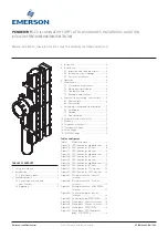
LED ILLUMINATOR FOR FLAT GLASS GAUGES, HAZARDOUS LOCATION
INSTALLATION, OPERATION AND MAINTENANCE INSTRUCTIONS
Before installation, these instructions must be carefully read and understood.
TABLE OF CONTENTS
1. Safety information ......................................... 2
2. Introduction ................................................... 2
2.1 System description ................................. 2
3. Available models ........................................... 2
3.1 Power requirements and
specifications .......................................... 2
3.2 Approvals ................................................ 3
VCIOM-04486-EN 19/10
Emerson.com/FinalControl
© 2017 Emerson. All Rights Reserved.
4. Inspection ...................................................... 4
5. Installation ..................................................... 4
5.1 Inspection and cleaning of glass ........... 4
5.2 Installation of unit to gauge ................... 4
5.3 Electrical installation ............................. 5
6. Operation ....................................................... 6
7. Maintenance .................................................. 6
7.1 Preventative maintenance ..................... 6
7.2 Maintenance procedures ....................... 6
7.3 Troubleshooting ..................................... 6
7.4 Allowable modifications ......................... 6
8. Removal - disassembly - reassembly ......... 6
8.1 Disassembly ........................................... 6
8.2 Reassembly ............................................ 7
9. Packaging, storage and transportation ....... 7
9.1 Packaging ............................................... 7
9.2 Storage .................................................... 7
9.3 Transportation ........................................ 7
10. Disposal at end of useful life ........................ 7
11. Warranty ........................................................ 7
12. Telephone assistance ................................... 7
13. Transparent Gauge ....................................... 8
14. Reflex Gauge .................................................. 9
15. TSL/TSM Gauge ........................................... 10
Tables and figures
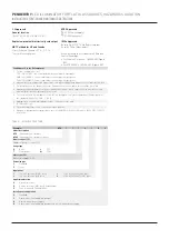
Table 1
Model structure ............................... 3
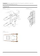
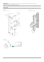
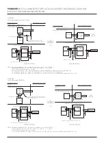
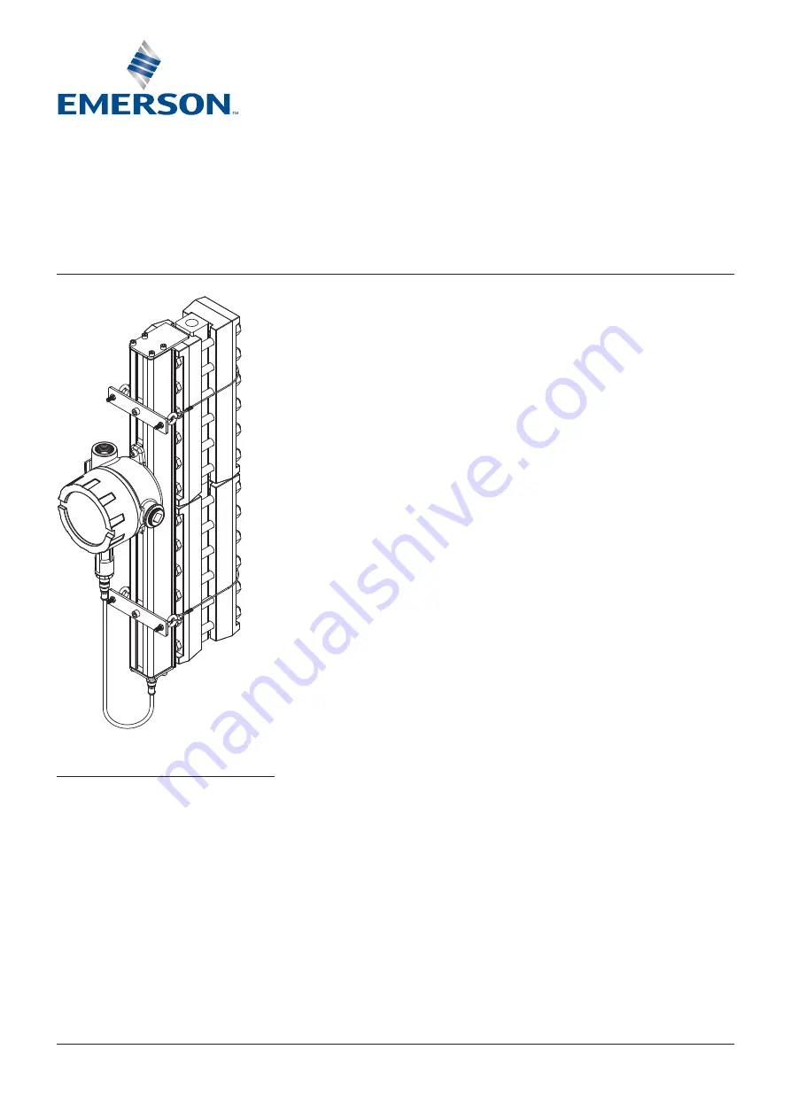
Figure 1A LED illuminator exploded view ....... 8
Figure 1B LED illuminator ISO view ................ 8
Figure 1C LED illuminator top view ................. 8
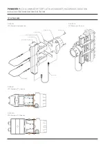
Figure 2A LED illuminator exploded view ....... 9
Figure 2B LED illuminator ISO view ................ 9
Figure 2C LED illuminator top view ................. 9
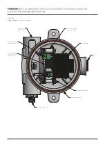
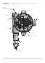
Figure 3A LED illuminator exploded view ..... 10
Figure 3B LED illuminator ISO view .............. 10
Figure 3C LED illuminator TSL top view ....... 10
Figure 3D LED illuminator TSM top view ...... 10
Figure 4A Wiring installation - General
locations ......................................... 11
Figure 4B Wiring installation - Division
locations ......................................... 12
Figure 4C Wiring installation - ATEX/IECEx
locations ......................................... 13
Figure 5A Control drawing for division
locations ......................................... 14
Figure 5B Control drawing ATEX/IECEx ........ 14
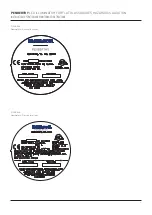
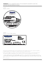
Figure 6A Nameplate - General locations .... 15
Figure 6B Nameplate - Division locations .... 15
Figure 6C Nameplate - ATEX/IECEx .............. 16
Figure 6D Nameplate - LED Illuminator
body - ATEX/IECEx ......................... 16


