background image

NELSON

INSTALLATION 

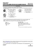
AXPTC125 POWER TEE SPLICE CONNECTION KIT

INSTRUCTIONS 

TULSA, OK  74146      

TEL 918-627-5530

FAX 918-641-7336

www.nelsonheaters.com

GA-5052 Rev. 3  

Sheet 1 of 10 

August 2017 

The AXPTC125 Power Tee Splice Connection Kit is 
designed to connect three heater cables in a tee splice 
configuration and with the removable plug can also connect 
the heating cables to customer supplied power wiring. This 
kit is designed for use with all wattages of Nelson Heat Trace 
CLT-J(ordinary locations), CLT-JT(ordinary locations), LT-J, 
LT-JT, UT-1, QLT-J, HLT-J and XLT-J heater cables. The 
AXPTC125 is rated IP66/NEMA 4X. The AXPTC125 
connection kit may be used to connect multiple heater 
segments, connect different wattage cables together or to 
provide access to serviceable equipment.  

These instructions are to be used together with the 
installation and maintenance instructions for self-regulating 
heater cable (GA-1765). 
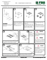
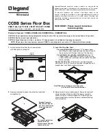
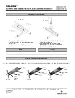
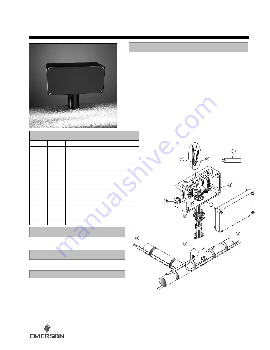
KIT CONTENTS 

QTY 

ITEM 

DESCRIPTION 

ENCLOSURE WITH TERMINAL BLOCKS 

POWER TERMINATION 

END TERMINATION 

SILICONE ADHESIVE 

ENCLOSURE ADAPTER 

STANDOFF 

LOCKNUT 

GREEN/YELLOW TUBE 

CABLE CLAMP 

10 

CABLE TIE (not shown) 

11 

STOPPING PLUG AND LOCKNUT 

12 

GUIDE TUBES (not shown) 

13 

PRODUCT LABEL (not shown) 
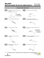
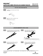
Pipe Clamp 

– PC03, PC12 or PC20 (included)

Fiberglass Tape 

– GT6 or GT60


HC-SPA Small Pipe Adapter 

– For 1.0”

(25 mm) diameter pipe and below.


Utility Knife

Wire Cutters

Adjustable Wrench 

(52mm [2.1”] size)

Needle Nose Pliers

Small Flat Blade Screwdriver

Large Slotted Screwdriver

Allen wrench 

(10mm [3/8”] size)

DESCRIPTION 

INSTALLATION ACCESSORIES 

OPTIONAL INSTALLATION MATERIAL 

RECOMMENDED TOOLS

Summary of Contents for NELSON AXPTC125

Page 1: ...age cables together or to provide access to serviceable equipment These instructions are to be used together with the installation and maintenance instructions for self regulating heater cable GA 1765 KIT CONTENTS QTY ITEM DESCRIPTION 1 1 ENCLOSURE WITH TERMINAL BLOCKS 3 2 POWER TERMINATION 3 3 END TERMINATION 1 4 SILICONE ADHESIVE 1 5 ENCLOSURE ADAPTER 1 6 STANDOFF 1 7 LOCKNUT 3 8 GREEN YELLOW TU...

Page 2: ... cable grommet into standoff and clip into place Insert heating cables through standoff allowing approximately 12 31 cm of cable for terminations Use cable lubricant if necessary Proceed to Heating Cable Terminations STANDOFF POSITIONING CABLE CONSTRUCTION DETAILS STEP 1 STEP 2 18 46 cm 12 31 cm 18 46 cm 18 46 cm LT UT 1 SELF REGULATING CABLE HLT QLT XLT SELF REGULATING CABLE CLT SELF REGULATING C...

Page 3: ... create a bulge At the bulge separate the braid to make an opening Bend heating cable at opening and pull the cable through Lightly cut around the cable inner jacket Cut up the middle of the inner jacket Bend cable to break inner jacket and remove Shave the core material from the outside of each bus wire 6 152 mm 7 178 mm Do Not Cut Braid Do Not Cut or Nick Bus Wires HEATING CABLE PREPARATION 3 No...

Page 4: ...bes into power termination fitting if required Note XLT cable will need to be installed without the assistance of guide tubes Insert buss wires into guide tubes if used Make sure that all buss wire strands are inserted through fitting tubes Remove guide tubes if used previously Squeeze power termination opening and fill void with silicone adhesive Push power termination to overlap jacket The silic...

Page 5: ...t between bus wires Pinch end termination body and fill void with silicone adhesive Push termination firmly onto heating cable 13 mm 1 2 3 4 5 6 Slide green yellow tubing over braid Trim bus wires and braid as necessary 13 mm END TERMINATION INSTALLATION 5 POWER TERMINATION INSTALLATION WARNING Do not megger or hipot until silicone completely cured Braid must be kept from bus wires or shorting may...

Page 6: ...bove top of standoff body Carefully slide enclosure adapter over cable terminations Screw enclosure adapter into standoff until fully seated at positive stop Mount standoff securely to pipe Insert supplied cable tie through slot provided to prevent possible rotation of enclosure 1 38 mm Note For pipes 1 25mm and below install HC_SPA purchased separately between standoff and pipe HC SPA adapter for...

Page 7: ...sure cover STEP 9 FINAL ASSEMBLY Install enclosure and secure to enclosure adapter with supplied locknut Do not over tighten locknut Enclosure may be rotated in 90 increments to match installation requirements STEP 7 90 Locknut Cable Clamp Install cable clamp over heating cables at top of enclosure adapter Tighten cable clamp with supplied screws Do Not over tighten STEP 8 ELECTRICAL WIRING Ground...

Page 8: ...s CIR NO Electrical circuit heating cable connected too CAT NO Type of heating cable used VOLTS Operating voltage of heating cable Max 277VAC AMPS Operating current of heating cable Max 18A continuous current 25A for XLT cable STEP 10 OPTIONAL CUSTOMER SUPPLIED POWER CONNECTION WIRING Remove stopping plug and locknut Install flex conduit and drain as shown Terminate power and ground wires to termi...

Page 9: ...n this connection system may present a hazard from static electricity Only surface cleaning with a damp cloth is acceptable Routine maintenance is required to maintain compliance with health and safety legislation Check that the cover gasket is in place and not damaged each time the enclosure is closed Check that all cover screws are in place and secure each time the enclosure is closed Check the ...

Page 10: ... been assured by compliance with ATEX EN 60079 0 2012 A11 2013 EN 60079 30 1 2007 EN 60079 7 2007 EN 60079 31 2014 IECEx IEC 60079 0 2011 IEC 60079 30 1 2007 IEC 60079 7 2006 IEC 60079 31 2013 IECEx KEM 07 0041 0344 Ex e IIC T6 T5 Gb for LT UT 1 Series KEMA 07ATEX0124 Ex e IIC T3 Gb for HLT QLT XLT Series Ex tb IIIC T80 o C T95 o C Db for LT UT 1 Series II 2 G D Ex tb IIIC T195 o C Db for HLT QLT ...

Reviews: