


Outside Plant Equipment
Proprietary Information
Page 1 of 21
Emerson Network Power
Wireline Products
631-205-105
Version 01, January 2009
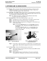
MESA
®
SOLE
OUTDOOR ELECTRONIC ENCLOSURE
DESCRIPTION AND INSTALLATION
1. ABOUT THIS DOCUMENT
1.1
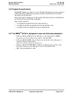
Purpose -
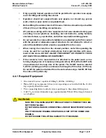
This practice provides a description and installation instructions for the
MESA
®
SOLE (Modular Electronic Sealed Architecture) cabinet (Fig. 1).
1.2
Reason For Reissue -
Whenever this practice is reissued, the reason for reissue will
be stated in this paragraph.
1.3
Information Not Provided in this Practice -
Refer to other local practices or
building codes as applicable for the correct methods, tools and materials to be used
in performing procedures not specifically described in this document.
Note:
The information contained in this practice is subject to change
without notice and may not be suitable for all applications.
Fig. 1 : MESA
®
SOLE


