background image


Reference Manual 

00809-0100-3003, Rev AA 

May 2019 

GDU-Incus Ultrasonic Gas Leak Detector 


Summary of Contents for GDU-Incus

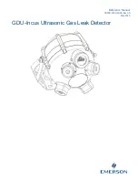
Page 1: ...Reference Manual 00809 0100 3003 Rev AA May 2019 GDU Incus Ultrasonic Gas Leak Detector ...

Page 2: ......

Page 3: ...alist knowledge is an absolutely necessary condition for working with and on the GDU Incus Authorized personnel for installing operating servicing and maintaining the GDU Incus are instructed and trained qualified personnel of the operating company and the manufacturer It is the responsibility of the operating company to Train staff Observe safety regulations Follow the reference manual Operators ...

Page 4: ...ion use or maintenance of any product Responsibility for proper selection use and maintenance of any Emerson product s remains solely with the purchaser and end user To the best of Emerson s knowledge the information herein is complete and accurate Emerson makes no warranties expressed or implied including implied warranties of merchantability and fitness for a particular purpose with respect to t...

Page 5: ...ligated to pay any costs or charges incurred by Buyer or any other party except as may be agreed upon in writing in advance by Seller All costs of dismantling reinstallation freight and the time and expenses of Seller s personnel and representatives for site travel and diagnosis under this limited warranty clause shall be borne by Buyer unless accepted in writing by Seller Goods repaired and parts...

Page 6: ......

Page 7: ...xe 14 3 5 1 General 14 3 5 2 Wiring configurations 18 3 6 Exe Junction Box Wiring Exe Incus Only 19 3 7 External cables 20 3 8 External ground 20 3 9 Commissioning 21 3 9 1 Visual inspection 21 3 9 2 Power up 22 Section 4 Operation 23 4 1 Normal operation 23 4 1 1 Alarm level 23 4 1 2 Delay time 25 4 1 3 Automatic self test 27 4 2 Sensor functionality check 27 4 3 Output options 27 4 3 1 Relay Opt...

Page 8: ...7 3 1 Detection frequency range 36 7 3 2 Dynamic range 36 7 3 3 Response time 36 7 3 4 Detection coverage 36 7 3 5 Start up time 36 7 4 Electrical 36 7 4 1 Operating voltage range 36 7 4 2 Power consumption 36 7 4 3 Cable entry 36 7 5 Environmental 37 7 5 1 Storage temperature 37 7 5 2 Operating temperature 37 7 5 3 Relative humidity 37 7 5 4 Metallurgy 37 7 5 5 Ingress protection 37 7 5 6 Weight ...

Page 9: ...design makes the sensing heads virtually indestructible and totally immune to temperature moisture and other contaminants found in hazardous industry The GDU Incus uses a continuous electronic monitoring test feature to ensure complete functionality The GDU Incus has a large dynamic range which allows use in a wide range of applications from offshore platforms to gas transportation systems The mul...

Page 10: ...include the following information 1 RMA number provided to you by Emerson 2 Company name and contact information 3 Purchase order from your company authorizing repairs or request for quote 4 Ship all equipment prepaid to Emerson 158 Edinburgh Avenue Slough Berkshire SL1 4UE UK 5 Mark all packages with Return for Repair and include RMA number Pack items to protect them from damage and use anti stat...

Page 11: ...mbient ultrasound level gas pressure leak size temperature of the gas and environmental conditions Emerson has formulated a series of calculations that take all of these external factors into account and are able to determine accurate coverage information for most installations Please contact an Emerson representative to advise on appropriate coverage for each installation The GDU Incus detection ...

Page 12: ...ure all cable entry threads are sealed with an appropriate plug to eliminate water ingress and thread damage At installation all shipping cable entry plugs are to be removed and replaced with suitably approved Ex d cable glands or blanking plugs to meet hazardous locations requirements If the GDU Incus is to be installed in a Zone 1 Hazardous Area an Exd barrier seal must be used Identification ta...

Page 13: ... as normal background noise such as pressure release valves etc If any are present in the detector range of coverage please contact Emerson or monitor the detector when activated to ensure immunity 3 3 1 Mechanical installation The GDU Incus incorporates a dedicated flameproof terminal compartment certified to Ex d and a flameproof main electronics compartment certified to Ex d both sealed to IP66...

Page 14: ...formation can be easily viewed Figure 3 2 3D View of Detector Coverage The GDU Incus utilizes four independent sensor heads for full coverage Figure 3 2 shows a 3D view of the coverage detector not to scale at a 3m 10 foot height above floor level with the detector pointing vertically downwards The GDU Incus coverage is specified as meters radius at the floor level as this is the minimum sensing d...

Page 15: ...D View of Detector Coverage Figure 3 4 Coverage When Mounted at an Angle Figure 3 4 shows coverage when the detector is mounted at an angle This method is recommended when the detector is mounted close to a wall or in an enclosed space to increase the coverage area ...

Page 16: ... Wall Flat Surface Mounting Diagram When mounting on a vertical flat surface such as a wall with no significant vibration it is sufficient to use the standard mounting bracket supplied with the GDU Incus If vibration at fixing point is suspected please contact an Emerson representative for additional options ...

Page 17: ...Template Figure 3 4 shows the position of the mounting slots on the wall mounting bracket supplied with the standard GDU Incus Pairs of Ø10 mm holes are to be drilled on the mounting surface between 30 mm and 70 mm apart with a vertical distance of 190 mm between the two pairs of holes ...

Page 18: ... be used lower than 10 ft 3 m but coverage may be reduced please contact an Emerson representative for details The pole should be mounted to local standards and be capable of supporting the detector weight at the installation height when environmental factors are taken into consideration The GDU Incus is attached to the pole using 2 U bolts fixed to the pole mounting adapter wall bracket can be us...

Page 19: ...ure 3 8 Exe Incus Mounting Diagram The Exe Incus can either be wall or pole mounted as detailed above in sections 3 4 1and 3 4 2 respectively however the bracket holding the exe junction box bracket must be located between the wall mounting bracket and the standard bracket during installation ...

Page 20: ...ment to be DNV certified the GDU Incus must be mounted using a DNV Mounting Bracket Part Number GDU 02 412 as shown in Figure 3 9 Figure 3 9 DNV Mounting Diagram Figure 3 9 shows the mounting arrangement for DNV Installation All bolts should be torqued to 45 Nm and spring washers are to be used in all cases ...

Page 21: ...lling template Figure 3 4 shows the position of the mounting slots on the DNV mounting bracket supplied with the DNV Incus Pairs of Ø10 mm holes are to be drilled on the mounting surface between 70 mm and 90 mm apart with a vertical distance of 75 mm between the two pairs of holes ...

Page 22: ...n 40 F and 185 F 40 C and 85 C and the heated variant is temperature rated between 67 F and 185 F 55 C and 85 C Ensure that all cable is rated to the appropriate temperature of installation 3 5 1 General Wiring codes and regulations may vary Wiring must comply with all applicable regulations relating to the installation of electrical equipment in a hazardous area and is the responsibility of the i...

Page 23: ...standard as the enclosure to maintain certification and are suitable for the size of cable used If the GDU Incus is to be installed in an ATEX Zone 1 Hazardous Area an Exd barrier seal must be used All FM approved units US and Canada must be sealed within 18 in 457 2 mm of enclosure entry using a suitably rated conduit seal Thread size for cable entry is specified for each position on the terminal...

Page 24: ...ble shield should be connected to instrument earth in the control room only unless extra RFI protection is required and all local and site grounding regulations are met in which case the shield is to be terminated to local ground via one of the internal earth points shown in Figure 3 13 ...

Page 25: ...ure 3 13 shows a view of the GDU Incus with the terminal cover removed For single entry enclosures customer cable entry is via position 1 whereas dual entry enclosures will use positions 1 and 2 The terminals are separated into power and communications for terminal row 1 and relay outputs for terminal row 2 ...

Page 26: ...ndard 3 wire connection cables should be connected to Terminal Row 1 in positions 24 V 0 V and current loop output connected to the mA terminal Maximum loop resistance 500 Ω Current source is the standard default operation current sink is an option and should be specified at time of order Relay data 1 4 A 30 Vdc switch voltage For a full description of fault relays refer to section 4 3 1 for more ...

Page 27: ...ons of the cable entries for the terminals inside the Exe Junction box The Exe Incus is configured for a standard 3 wire connection cables should be connected in positions 24 V 0 V and current loop output connected to the mA terminal Cable entry is via suitable hazardous area approved and ingress protection certified cable glands customer supply or conduit Ensure cable glands are ingress protected...

Page 28: ...d on a nominal input voltage of 24 VDC Conductor Cross Sectional Area Gauge 0 5 mm 20 AWG 1 0 mm 18 AWG 1 5 mm 16 AWG 2 5 mm 14 AWG Maximum Cable Length for Standard Non Heated Incus 540 m 1770 ft 855 m 2800 ft 1360 m 4470 ft 2170 m 7120 ft Maximum Cable Length for Heated Incus 75 m 240 ft 115 m 380 ft 185 m 620 ft 300 m 990 ft 3 8 External ground The detector housing should be connected to local ...

Page 29: ...able for operating environment Ensure correct cable gland installation and appropriate certification or local regulations have been observed Check correct cable installation in the terminal compartment ensure terminal compartment flame paths and seals are intact Non Exe units only Ensure incoming cable is threaded through Ferrite beads Figure 3 11 Non Exe units only Tighten terminal cover bolts to...

Page 30: ...al any faults that may be present Factory default options can be found in section 4 1 and a list of faults can be found in section 4 6 In addition the display will show the real time ultrasonic sound level and the detector will become responsive to RS485 commands for function setup and all relays will be energized or de energized as per defaults Note If the GDU Incus has been factory set for speci...

Page 31: ...and ready to receive commands 4 1 1 Alarm level The Alarm Level is the ultrasonic sound level at which an alarm state is triggered During the alarm state the display flashes the relays switch states and the current loop becomes active if one or more sensors were in fault mode if no sensors are in fault the current loop will already be outputting dB level To avoid false alarms it is recommended to ...

Page 32: ...arms however care should be taken to survey the area of installation for potential spurious noise If background levels are unknown typical historical process background levels can be used along with a safety factor Please contact an Emerson representative for historical values and guidance Alarm levels can be set in the detector or at the control panel Most installations set the alarm levels in th...

Page 33: ...oise level remains above the alarm level threshold for the duration of the delay time the alarm will be activated as shown in Figure 4 2 Alarm delay time should be assessed with regards to the following Detector proximity to release valves and intermittent ultrasonic noise sources Process leak severity toxic non toxic acceptable leak size before alarm Existing site protocols and local regulations ...

Page 34: ...l of man made ultrasonic noise produced through normal maintenance procedures Noise 3 is a longer spurious noise of approx 13 seconds typical of a pressure relief valve Delay time is introduced to ignore spurious noise spikes as the detector will reset when noise level drops below the alarm level before the delay time is reached Figure 4 4 Graph Showing Alarm Activation with Spurious Noise and Lea...

Page 35: ...e result without interrupting the normal functionality of the sensor If drift component failure or damage occurs a fault is signaled refer to section 4 6 4 2 Sensor functionality check The sensors on the GDU Incus are factory calibrated and do not require adjustment Before operation functionality checks are recommended to ensure correct installation On power up the GDU Incus will perform a diagnos...

Page 36: ...rmation on setup of the relays 4 4 Display The GDU Incus incorporates a 5 digit x 7 segment 0 31 in high x 0 16 in wide 8 mm high x 4 mm wide character LED display with red numerals as standard During operation the real time dB level is continuously shown while below the programmed alarm level and flashing when above the programmed alarm level Figure 4 5 Example of real time dB level display 53dB ...

Page 37: ...e left side shows the mA output tolerance band internal fault is set for a 1 0 mA output with a tolerance of 0 8 to 1 2 mA for example Normal operation is shown with an upper tolerance of 4 7 mA 0 3 mA as the gain is usually set to a minimum working level of 47 dB mA outputs are grouped in descending order to signify importance and to allow for instant status recognition see section 4 6 Normal ope...

Page 38: ... of power to the detector or a serious microprocessor fault If a fault occurs due to loss of power the fault will be cleared when power is reapplied to the detector If a serious microprocessor fault occurs the GDU Incus should be returned to Emerson for repair 4 7 RS485 digital interface The GDU Incus incorporates an RS485 digital interface which allows access to sensor status and setting informat...

Page 39: ...us if the Heater option is fitted otherwise will report the same data as the Secondary Variable A Device description DD file for Emerson AMS and 375 475 field terminals is available from Emerson In addition the unit can be used with FDT frame applications using a generic DTM Full technical details of the HART Interface are provided in the GDU INCUS HART Field Device Specification document MAN GDU ...

Page 40: ...ication kit can be used to simulate an actual gas release to test both functionality and performance of ultrasonic gas detectors by generating a burst release representative of that expected in the event of a gas leak The GDU PTV 01 should be used at the perimeter of the detector coverage to ensure that all leaks will be detected It is recommended that all alarms are disabled and the 4 20 mA outpu...

Page 41: ...O ring Upper Replacement terminal cover O ring for upper position standard Terminal Cover O ring Lower Replacement terminal cover O ring for lower position standard Refer to individual spare part installation sheets for further information Description Part number Terminal Fastener Kit Replacement Terminal Cover fasteners and retaining washers GDU 02 TCFK Terminal Cover O ring Upper GDU 02 TCU Term...

Page 42: ...trap to allow remote independent testing of any ultrasonic gas leak detector from floor level Note the test transmitter is not hazardous area approved and will require a hot work permit PTV Kit Consists of two 10 liter nitrogen gas cylinders 150 BAR and a high pressure gas regulator which are attached to a trolley for portability Refer to individual accessory datasheets for further information or ...

Page 43: ... 1 3 Self test Continuous electronic check of sensor integrity 7 1 4 Calibration Factory set 7 2 Output signal 7 2 1 4 20 mA Current source 4 20 mA corresponds to 40 to 120 dB SPL Maximum load resistance 500 Ω standard Current sink 4 20 mA option 7 2 2 Digital RS485 interface 7 2 3 Relay 1 Error Fault NO or NC option Load 1 4 A max Switch Voltage 30 Vdc max Contact resistance 70 mΩ 7 2 4 Relay 2 A...

Page 44: ... to 65 ft 2 to 20 m radius leak pressure size and background level dependent Greater distances may be achieved subject to application consultation 7 3 5 Start up time Less than 5 seconds 7 4 Electrical 7 4 1 Operating voltage range 15 to 30 Vdc 7 4 2 Power consumption Standard Unit 250 mA at maximum display brightness during normal operation Heated Unit 1 5 A at maximum display brightness and with...

Page 45: ...85 C Heated Unit 67 F to 185 F 55 C to 85 C 7 5 3 Relative humidity Humidity operating 0 to 100 relative humidity 7 5 4 Metallurgy Stainless steel AISI 316 7 5 5 Ingress protection IP66 IP67 Type 4X 7 5 6 Weight Approx 39 8 lb 18 kg 7 5 7 Dimensions without bracket Ø8 in x 10 in Ø210 mm x 272 mm 7 6 Warranty 18 months after shipment or 12 months after installation whichever comes first ...

Page 46: ...t contain important information for installation and use which are detailed below Figure 8 1 shows the position of the nameplate certification plate and the terminal cover plate The plates supply information to comply with ATEX Directive 2014 34 EU ensure that all three are fitted and clearly legible before installation Figure 8 2 Manufacturing nameplate ...

Page 47: ...e Manual 00809 0100 3003 Rev AA May 2019 39 Figure 8 3 ATEX IECEx Certification nameplate Standard Incus Figure 8 4 ATEX IECEx Certification nameplate Heated Incus Variant Figure 8 5 FM Certification nameplate ...

Page 48: ...r label Figure 8 7 FM terminal cover label Figure 8 6 and Figure 8 7 show the ATEX IECEx and FM Terminal cover labels respectively The thread sizes of the enclosure entries situated below the label are shown on the label If the thread size box is empty the thread position is not machined ...

Page 49: ... H2 Gb T4 IP66 IP67 55 C 40 C Ta 85 C ITS 10 0004X 8 4 FM US Canada Class I Div 1 Groups B C and D T4 Class I Zone 1 AEx Ex d ib IIB H2 T4 40 C Ta 85 C Type 4X 3043275 8 5 EAC 1Ex d ib IIB H2 T4 Gb X 55 C 40 C Ta 85 C RU C GB ГБ04 B 00297 8 6 INMETRO Ex d ib IIB H2 T4 Gb 55 C 40 C Ta 85 C UL BR 15 0063X 8 7 KCs Ex d ib IIB H2 T4 55 C 40 C Ta 85 C 14 KB4BO 0294X ...

Page 50: ... ATEX IECEx CE Tamb 40 C to 85 C 40 F to 185 F B ATEX IECEx CE Tamb 55 C to 85 C 67 F to 185 F E EAC Tamb 55 C to 85 C 67 F to 185 F Russia Kazakhstan Belarus F FM Tamb 40 C to 85 C 40 F to 185 F USA Canada K KCs Tamb 40 C to 85 C 40 F to 185 F Korea M INMETRO Tamb 40 C to 85 C 40 F to 185 F Brazil Level 4 Output H Current Source HART Standard J Current Sink HART Level 5 Mounting A Standard bracke...

Page 51: ......

Page 52: ...ic of Singapore T 65 777 8211 F 65 777 0947 SAFETY CSC Emerson com 2019 Emerson All rights reserved The Emerson logo is a trademark and service mark of Emerson Electric Co All other marks are property of their respective owners The contents of this publication are presented for information purposes only and while effort has been made to ensure their accuracy they are not to be construed as warrant...

Reviews: