background image

www.Fisher.com

D100305X012

Type 655 and 655R Actuators 
for Self-Operated Control

Contents

Introduction

1

. . . . . . . . . . . . . . . . . . . . . . . . . . . . . . . 

Scope of Manual

1

. . . . . . . . . . . . . . . . . . . . . . . . . 

Description

1

. . . . . . . . . . . . . . . . . . . . . . . . . . . . . . 

Specifications

2

. . . . . . . . . . . . . . . . . . . . . . . . . . . . 

Installation

2

. . . . . . . . . . . . . . . . . . . . . . . . . . . . . . . . 

Actuator Mounting

3

. . . . . . . . . . . . . . . . . . . . . . . . 

Loading Connections

6

. . . . . . . . . . . . . . . . . . . . . . 

Startup

6

. . . . . . . . . . . . . . . . . . . . . . . . . . . . . . . . . . . 

Startup for Pressure-Reducing Service

6

. . . . . . 

Startup for Pressure-Relief Service

7

. . . . . . . . . 

Adjustment for Pressure-Reducing or

Pressure-Relief Service

7

. . . . . . . . . . . . . . . . . 

Shutdown

7

. . . . . . . . . . . . . . . . . . . . . . . . . . . . . . . . . 

Maintenance

7

. . . . . . . . . . . . . . . . . . . . . . . . . . . . . . 

Actuator

8

. . . . . . . . . . . . . . . . . . . . . . . . . . . . . . . . . 

Top-Mounted Handwheel

10

. . . . . . . . . . . . . . . . . 

Parts Ordering

12

. . . . . . . . . . . . . . . . . . . . . . . . . . . . 

Parts List

12

. . . . . . . . . . . . . . . . . . . . . . . . . . . . . . . . 

Introduction

Scope of Manual

This instruction manual provides installation,
adjustment, maintenance, and parts ordering for the
Type 655 and 655R actuators and the top-mounted
handwheel. Refer to separate instruction manuals
for information about valves and accessories used
with these actuators.

Do not install, operate, or maintain 655 and 655R
actuators without first 

D

 being fully trained and

qualified in valve, actuator, and accessory
installation, operation, and maintenance, and 

D

 carefully reading and understanding the contents

of this manual. If you have any questions about
these instructions, contact your Emerson Process
Management

t

 sales office before proceeding.
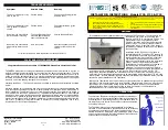
Description

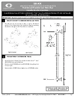
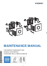
Type 655 and 655R actuators (figure 1) are
pressure-actuated, spring-and-diaphragm actuators
used in conjunction with various valves to provide

W0466-1 / IL

Figure 1. Type 655-ED Pressure-Reducing Valve

control for a wide variety of pressure regulation
applications. Type 655 actuators are used for
pressure-reducing service when mounted on
push-down-to-close valves such as the Design ED
and ET valves. Type 655R actuators are used for
pressure-relief service when mounted on
push-down-to-open valves such as the Design EDR
and ETR valves. Both types are self-operated and
direct-acting; that is, increasing pressure in the
diaphragm casing forces the actuator stem
downward, and decreasing the pressure allows the
actuator spring to lift the actuator stem upward.

Note

Neither Emerson, Emerson Process
Management, nor any of their affiliated
entities assumes responsibility for the
selection, use and maintenance of any
product. Responsibility for the
selection, use, and maintenance of any
product remains with the purchaser
and end-user.

Instruction Manual

Form 1292
July 2007

655 and 655R Actuators

Summary of Contents for Fisher 655

Page 1: ... any questions about these instructions contact your Emerson Process Managementt sales office before proceeding Description Type 655 and 655R actuators figure 1 are pressure actuated spring and diaphragm actuators used in conjunction with various valves to provide W0466 1 IL Figure 1 Type 655 ED Pressure Reducing Valve control for a wide variety of pressure regulation applications Type 655 actuato...

Page 2: ... ACTUATOR SIZE Kg Lb 3A 3B 32 33 20 45 34 35 36 23 50 4A 4B 42 43 29 65 44 45 46 34 75 Specifications Specifications for the Type 655 and 655R actuators are shown in table 1 Information for a specific actuator is also found on the nameplate of that actuator Installation WARNING To avoid personal injury or property damage caused by bursting of pressure retaining parts be certain the service conditi...

Page 3: ...ull travel and proper shutoff Refer to figure 3 for actuator mounting components Key numbers refer to figure 4 unless otherwise stated 1 Turn the adjusting screw key 10 into the yoke key 7 to force the diaphragm key 2 and diaphragm plate key 4 against the upper diaphragm casing key 1 2 Perform the following steps as appropriate for either push down to close or push down to open valve action CAUTIO...

Page 4: ... 7 2 0 2 2 8 0 4 6 3 32 1E795427082 1 8 26 3 8 55 1 5 22 2 6 38 35 45 1F176827092 0 1 2 0 0 4 5 9 0 2 2 5 0 4 5 5 42 1E793327082 2 2 32 4 5 65 1 8 26 3 7 53 1F176727032 0 1 1 5 0 3 4 4 0 1 1 5 0 3 4 2 42 1E795427082 1 8 26 3 8 55 1 5 22 3 1 45 1F714427112 0 07 1 0 0 2 2 9 0 09 1 3 0 2 2 8 32 42 1E792427082 1 5 22 3 2 47 1 2 18 2 6 38 36 1E793327082 0 4 5 8 0 9 13 0 3 5 0 0 5 7 7 32 42 1F714327092 ...

Page 5: ... 26 4 33 43 406 63 0 374 58 0 366 56 8 358 55 5 345 53 5 340 52 7 335 52 0 330 51 2 318 49 3 307 47 6 34 44 600 93 0 547 84 8 534 82 8 523 81 0 508 78 8 502 77 8 497 77 0 490 76 0 474 73 5 465 72 0 35 45 865 134 0 834 129 2 821 127 2 809 125 4 788 122 2 777 120 5 768 119 0 759 117 6 736 114 1 723 112 0 36 46 1230 190 0 1170 181 5 1150 179 0 1140 177 0 1120 173 5 1110 172 3 1100 171 0 1100 169 8 10...

Page 6: ... tighten the yoke locknut with a hammer and punch Note Changing the spring adjustment will not change the actuator pressure range for that particular spring see table 2 Changing the spring adjustment merely shifts the position of the spring either up or down so that valve travel can coincide with the actuator pressure setting range 4 While monitoring loading pressure with a pressure gauge stroke t...

Page 7: ...unscrew the cap screw key 3 and lift the diaphragm plate key 4 out of the actuator body 3 Replace the spring and reassemble the actuator by following steps 5 and 6 of the Assembly portion of the Maintenance section Shutdown For both pressure reducing and pressure relief applications refer to figure 2 and follow the procedures described below 1 Close the upstream shutoff valve slightly 2 Slowly ope...

Page 8: ...ey 8 from rotating while performing the following procedure make sure the adjusting screw key 10 remains screwed into the yoke key 7 a Loosen the two hex nuts key 12 b Loosen the yoke locknut figure 3 with a hammer and punch and unscrew it from the valve bonnet c While lifting the actuator so that the valve plug is not forced against the seat rotate the entire actuator until the actuator stem dise...

Page 9: ...he diaphragm to tear or allow leakage 6 Place the upper diaphragm casing onto the lower diaphragm casing For size 3A and 4A actuators secure the casings with the cap screws key 19 For all other actuator sizes secure the casing with the cap screws and hex nuts keys 19 and 20 Note When you replace actuator diaphragms in the field take care to ensure the diaphragm casing bolts are tightened to the pr...

Page 10: ...mplished by removing the cap screws that secure the handwheel assembly to the upper diaphragm casing key 33 figure 6 key 141 figure 7 5 Turn the handwheel clockwise two or three turns Remove the hex nut key 22 figures 5 and 6 key 54 figure 7 and washer key 24 figures 5 and 6 key 134 figure 7 and lift off the handwheel 6 Unscrew the locknut key 27 figures 5 and 6 key 137 figure 7 from the handwheel...

Page 11: ...eys 19 and 20 figure 4 Note When you replace actuator diaphragms in the field take care to ensure the diaphragm casing bolts are tightened to the proper load to prevent leakage but not crush the material Perform the following tightening sequence with a manual torque wrench CAUTION Over tightening the diaphragm cap screws and nuts keys 19 and 20 can damage the diaphragm Do not exceed 27 NSm 20 lbfS...

Page 12: ...esponsibility for the selection use and maintenance of any product Responsibility for the selection use and maintenance of any product remains with the purchaser and end user Parts List Note Part numbers are shown for recommended spares only For part numbers not shown contact your Emerson Process Management sales office Actuator Key Description Part Number 1 Upper Diaphragm Casing 2 Diaphragm chlo...

Page 13: ...ART NOT SHOWN 31 Key Description Part Number 18 Drive Screw 19 Cap Screw 20 Hex Nut 21 Cap Screw Top Mounted Handwheel Sizes 3A 4A 3B 4B 22 Hex Jam Nut 24 Washer 25 Handwheel 26 Handwheel Stem 27 Hex Jam Nut 28 Handwheel Body 29 O Ring nitrile 1D237506992 30 O Ring nitrile not shown Sizes 3B 4B only 1D267306992 31 Groove Pin 32 Pusher Plate 33 Cap Screw 34 Travel Stop Sizes 32 thru 46 51 Handwheel...

Page 14: ...red 22 123 1290 290 Aluminum dark green 43 246 2420 545 Dark green 64 368 3750 843 Aluminum 86 490 4720 1060 Dark blue 107 612 5200 1187 Aluminum dark blue 145 830 7250 1630 Light blue 220 1260 8184 1840 Light green 257 1470 9790 2200 Light grey 310 1770 11 600 2600 Yellow 368 2100 13 500 3045 Dark grey 129 735 5160 1160 Aluminum brown 175 1000 7000 1575 White 441 2520 14 010 3150 BV8008 E DOC Fig...

Page 15: ...655 and 655R Actuators Instruction Manual Form 1292 July 2007 15 ...

Page 16: ...e the designs or specifications of such products at any time without notice Neither Emerson Emerson Process Management nor any of their affiliated entities assumes responsibility for the selection use and maintenance of any product Responsibility for the selection use and maintenance of any product remains with the purchaser and end user EFisher Controls International LLC 1975 2007 All Rights Rese...

Reviews: