www.Fisher.com
Fisher
™
546NS Electro-Pneumatic Transducer
Contents
Introduction
. . . . . . . . . . . . . . . . . . . . . . . . . . . . . . . . .
Scope of Manual
. . . . . . . . . . . . . . . . . . . . . . . . . . . . .
Description
. . . . . . . . . . . . . . . . . . . . . . . . . . . . . . . . .
Specifications
. . . . . . . . . . . . . . . . . . . . . . . . . . . . . . .
564NS Qualification
. . . . . . . . . . . . . . . . . . . . . .
Educational Services
. . . . . . . . . . . . . . . . . . . . . . . . .
Installation
. . . . . . . . . . . . . . . . . . . . . . . . . . . . . . . . . .
Hazardous Area Classifications
. . . . . . . . . . . . . . . . .
Mounting
. . . . . . . . . . . . . . . . . . . . . . . . . . . . . . . . . .
Pressure Connections
. . . . . . . . . . . . . . . . . . . . . . . .
Diagnostic Connections
. . . . . . . . . . . . . . . . . . . . . .
Electrical Connections
. . . . . . . . . . . . . . . . . . . . . . . .
Operating Information
. . . . . . . . . . . . . . . . . . . . . . . . .
Adjustments
. . . . . . . . . . . . . . . . . . . . . . . . . . . . . . . .
Calibration
. . . . . . . . . . . . . . . . . . . . . . . . . . . . . . . .
Equipment Required
. . . . . . . . . . . . . . . . . . . . .
Calibration Procedure
. . . . . . . . . . . . . . . . . . . .
Recalibration
. . . . . . . . . . . . . . . . . . . . . . . . . . .
Changing Output Pressure Range
. . . . . . . . . . . . .
Reversing the Action
. . . . . . . . . . . . . . . . . . . . . . . .
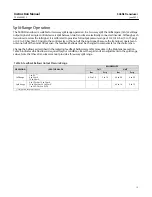
Split Range Operation
. . . . . . . . . . . . . . . . . . . . . . .
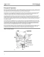
Principle of Operation
. . . . . . . . . . . . . . . . . . . . . . . .
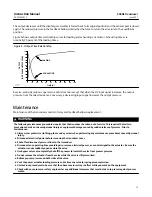
Maintenance
. . . . . . . . . . . . . . . . . . . . . . . . . . . . . . . .
Relay Removal and Replacement
. . . . . . . . . . . . . .
Replacing the Feedback Bellows Assembly
. . . . . .
Troubleshooting
. . . . . . . . . . . . . . . . . . . . . . . . . . . .
Electrical
. . . . . . . . . . . . . . . . . . . . . . . . . . . . . .
Pneumatic
. . . . . . . . . . . . . . . . . . . . . . . . . . . . .
Alignment
. . . . . . . . . . . . . . . . . . . . . . . . . . . . . . . . .
Span Adjustment
. . . . . . . . . . . . . . . . . . . . . . .
Torque Motor Frame
. . . . . . . . . . . . . . . . . . . .
Armature Travel Stop
. . . . . . . . . . . . . . . . . . . .
Coil
. . . . . . . . . . . . . . . . . . . . . . . . . . . . . . . . . . .
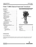
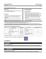
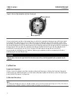
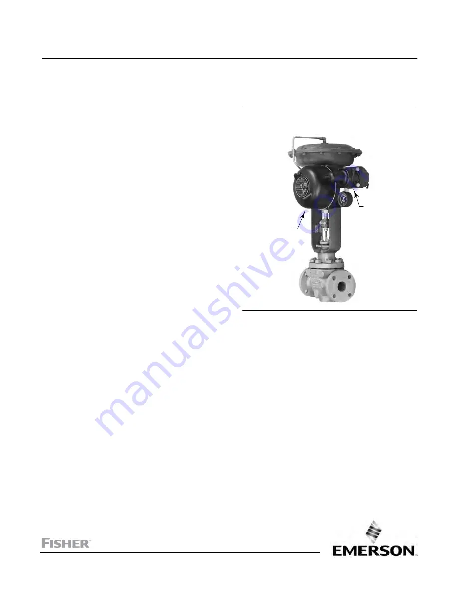
Figure 1. Fisher 546NS Electro‐Pneumatic Transducer
Mounted on a 657 Pneumatic Diaphragm Actuator
W2115
546NS
FILTER
REGULATOR
Parts Ordering
. . . . . . . . . . . . . . . . . . . . . . . . . . . . . . .
Repair Kits
. . . . . . . . . . . . . . . . . . . . . . . . . . . . . . . . . .
Parts List
. . . . . . . . . . . . . . . . . . . . . . . . . . . . . . . . . . .
Transducer
. . . . . . . . . . . . . . . . . . . . . . . . . . . . . . . .
Torque Motor
. . . . . . . . . . . . . . . . . . . . . . . . . . . . . .
Relay
. . . . . . . . . . . . . . . . . . . . . . . . . . . . . . . . . . . . .
Mounting Parts
. . . . . . . . . . . . . . . . . . . . . . . . . . . . .
Diagnostic Connections
. . . . . . . . . . . . . . . . . . . . .
Introduction
Scope of Manual
This instruction manual provides installation, operation, maintenance, and parts ordering information for the Fisher
546NS transducer and the 82 relay. Refer to separate manuals for instructions covering equipment used with the
transducer.
Instruction Manual
D103425X012
546NS Transducer
June 2021


