background image

www.Fisher.com

Fisher

 3610J and 3620J Positioners and 3622

Electro‐Pneumatic Converter

Contents

Introduction

2

. . . . . . . . . . . . . . . . . . . . . . . . . . . . . . . . .

Scope of Manual

2

. . . . . . . . . . . . . . . . . . . . . . . . . . . . .

Description

2

. . . . . . . . . . . . . . . . . . . . . . . . . . . . . . . . .

Type Number Description

5

. . . . . . . . . . . . . . . . . . . . .

Specifications

6

. . . . . . . . . . . . . . . . . . . . . . . . . . . . . . .

Educational Services

6

. . . . . . . . . . . . . . . . . . . . . . . . .

Installation

7

. . . . . . . . . . . . . . . . . . . . . . . . . . . . . . . . . .

Hazardous Area Classifications and

Special Instructions for “Safe Use” and
Installation in Hazardous Locations
for 3622 converter

7

. . . . . . . . . . . . . . . . . . . . . . . .

CSA

8

. . . . . . . . . . . . . . . . . . . . . . . . . . . . . . . . . . . .

FM

8

. . . . . . . . . . . . . . . . . . . . . . . . . . . . . . . . . . . . .

ATEX

9

. . . . . . . . . . . . . . . . . . . . . . . . . . . . . . . . . . .

IECEx

10

. . . . . . . . . . . . . . . . . . . . . . . . . . . . . . . . . .

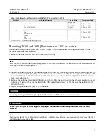
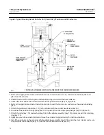
Mounting 3610J and 3620J Positioners 

on 2052 Actuators

11

. . . . . . . . . . . . . . . . . . . . . . . .

Changing Cams—Actuator Styles A, B,

C, and D

12

. . . . . . . . . . . . . . . . . . . . . . . . . . . . . . . .

Mounting 3611JP and 3621JP Positioners

on 585 and 585R Actuators

13

. . . . . . . . . . . . . . . .

Mounting 3611JP and 3621JP Positioners

on 585C and 585CR Actuators

15

. . . . . . . . . . . . . .

Installing the 3622 Electro‐Pneumatic

Converter

17

. . . . . . . . . . . . . . . . . . . . . . . . . . . . . . .

Changing Positioner Types

17

. . . . . . . . . . . . . . . . . . .

Pressure Connections

17

. . . . . . . . . . . . . . . . . . . . . . .

Supply Connection

18

. . . . . . . . . . . . . . . . . . . . . .

Output Connections

18

. . . . . . . . . . . . . . . . . . . . .

Instrument Connection

19

. . . . . . . . . . . . . . . . . .

Diagnostic Connections

20

. . . . . . . . . . . . . . . . . .

Vent Connection

21

. . . . . . . . . . . . . . . . . . . . . . . . . . .

Electrical Connections

for 3620J Positioners

22

. . . . . . . . . . . . . . . . . . . . . .

Calibration

22

. . . . . . . . . . . . . . . . . . . . . . . . . . . . . . . . . .

Minor Loop Gain Adjustment

23

. . . . . . . . . . . . . . . . .

Crossover Adjustment

24

. . . . . . . . . . . . . . . . . . . . . . .

3610J or 3620J Positioner,

Spring and Diaphragm Actuators

24

. . . . . . . .

3610JP, 3611JP, 3620JP, or 3621JP

Positioner, Piston Actuators

25

. . . . . . . . . . . .

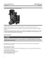
Figure 1. Typical Positioners

3610J POSITIONER WITH 

2052 ACTUATOR AND V500 VALVE

3620JP POSITIONER WITH

1061 ACTUATOR AND V500 VALVE

W4920-1 

X1284

Instruction Manual

D200149X012

3610J and 3620J Positioners

September 2017

Summary of Contents for Fisher 3610J

Page 1: ... 13 Mounting 3611JP and 3621JP Positioners on 585C and 585CR Actuators 15 Installing the 3622 Electro Pneumatic Converter 17 Changing Positioner Types 17 Pressure Connections 17 Supply Connection 18 Output Connections 18 Instrument Connection 19 Diagnostic Connections 20 Vent Connection 21 Electrical Connections for 3620J Positioners 22 Calibration 22 Minor Loop Gain Adjustment 23 Crossover Adjust...

Page 2: ...lation operation calibration maintenance and parts ordering information for Fisher 3610J and 3620J positioners i e 3610J 3610JP 3611JP 3620J 3620JP and 3621JP This manual also provides field installation information for the Fisher 3622 electro pneumatic converter Refer to separate instruction manuals for information on the actuator and control valve Contact your Emerson sales office or Local Busin...

Page 3: ...span Reverse Acting 3610JP and 3620JP 0 5 of output span Hysteresis 3610J 1 0 of output span 3620J 0 75 of output span 3610JP 0 5 of output span 3620JP 0 6 of output span Deadband 0 1 of input span Refer to table 3 for typical performance for 3611JP and 3621JP positioners Electromagnetic Compatibility for 3622 electro pneumatic converter Meets EN 61326 1 2013 Immunity Industrial locations per Tabl...

Page 4: ...ous Area CSA Intrinsically Safe Explosion proof Type n Dust Ignition proof DIV 2 FM Intrinsically Safe Explosion proof Type n Dust Ignition proof Non incendive ATEX Intrinsically Safe Flameproof Type n IECEx Intrinsically Safe Flameproof Type n Gas Atmospheres only Refer to Hazardous Area Classifications and Special Instructions for Safe Use and Installation in Hazardous Locations starting on page...

Page 5: ...uator 2 585C and 585CR Size 50 Actuator 2 585 and 585R Size 100 Actuator Standard 585 and 585R Size 100 Actuator with Boosters 3 Deadband 1 0 1 of input span 0 1 of input span 0 1 of input span 0 1 of input span Step Response 1 4 5 0 3 seconds 0 3 seconds 2 seconds 0 3 seconds Steady State Air Consumption 6 7 0 01 normal m3 min 0 4 scfm 0 01 normal m3 min 0 4 scfm 0 01 normal m3 min 0 4 scfm 0 01 ...

Page 6: ...tioner to make a 3620J 3620JP or a 3621JP positioner Specifications WARNING This product is intended for a specific range of pressure temperatures and other application specifications Applying different pressure temperature and other service conditions could result in malfunction of the product which could cause property damage or personal injury Specifications for the valve positioners are shown ...

Page 7: ...al gas is used as the supply medium and appropriate preventive measures are not taken Preventive measures may include but are not limited to one or more of the following Remote venting of the unit re evaluating the hazardous area classification ensuring adequate ventilation and the removal of any ignition sources 3620J 3620JP 3621JP positioners and the 3622 electro pneumatic converter do not meet ...

Page 8: ...amb 82 C Class I Division 2 GP A B C D T6 T6 Tamb 82 C Class II Division 1 GP E F G T5 T5 Tamb 82 C Class II Division 2 GP F G T6 T6 Tamb 82 C 1 These hazardous area classification also apply to 3620J positioners FM Intrinsically Safe Explosion proof Type n Dust Ignition proof Non incendive No special conditions for safe use Refer to table 5 for approval information Table 5 Hazardous Area Classifi...

Page 9: ...by EN 60079 1 Contact the manufacturer for information on the dimensions of the flameproof joints Electrical connections are typically made using either cable or conduit D If using a cable connection the cable entry device shall be certified in type of explosion protection flameproof enclosure d suitable for the conditions of use and correctly installed For ambient temperatures over 70_C cables an...

Page 10: ...of Gas Ex d IIC T5 Gb T5 Tamb 82 C Dust Ex tb IIIC T82 C Db Tamb 79 C II 3 G D Type n Gas Ex nA IIC T6 Gc T6 Tamb 82 C Dust Ex tc IIIC T85 C Dc Tamb 82 C 1 These hazardous area classification also apply to 3620J positioners IECEx Conditions of Certification Intrinsically Safe WARNING Substitution of components may impair intrinsic safety 40_C Ta 82_C T6 Ta 47_C T5 Ta 62_C T4 Ta 82_C Entity Paramet...

Page 11: ...e cam mounting screw heads key 83 figure 3 2 Install the desired cam key 82 on the actuator lever with the cam mounting screws key 83 Cams B and C use the cam adjustment indicator key 84 between the screw heads and the cam Align the cam adjustment indicator with the desired total valve rotation indication on the cam Cam A does not use the cam adjustment indicator and does not require adjustment 3 ...

Page 12: ...D POSITIONER WITH ACTUATOR COVER REMOVED GG00138 A Note Refer to the appropriate 1061 and 1069 instruction manual or contact your Emerson sales office or Local Business Partner for information on mounting on these actuators Changing Cams Actuator Styles A B C and D During the following procedures refer to figure 3 for part locations and refer to figure 28 for key number locations unless otherwise ...

Page 13: ...tment indicator key 84 between the screw heads and the cam Align the cam adjustment indicator with the desired total valve rotation indication on the cam Cam A does not use the cam adjustment indicator and does not require adjustment CAUTION To avoid parts damage do not completely stroke the actuator while the actuator cover is removed WARNING To avoid personal injury from moving parts keep finger...

Page 14: ... travel distance 3 Loosen the four captive cover screws and remove the positioner cover key 41 figure 28 4 Refer to the appropriate actuator instruction manual Loosen the four screws and remove the actuator blanking plate 5 Attach the positioner adapter key 113 to the actuator with four socket head screws key 54 6 Disconnect the positioner range spring key 150 figure 25 from the range spring hange...

Page 15: ...he actuator with two hex nuts key 197 4 Disconnect the positioner range spring key 150 figure 25 from the range spring hanger key 130 figure 25 5 Attach the feedback roller key 175 to the stem bracket key 195 with the button head screw key 173 6 Attach the positioner adaptor key 113 to the mounting bracket key 194 with four hex nuts key 197 and four hex socket cap screws key 54 7 Remove the positi...

Page 16: ...ER KEY 175 STEM BRACKET KEY 195 HEX NUT KEY 197 FEEDBACK ROLLER BUTTON HEAD SCREW KEY 173 HEX SOCKET CAP SCREW KEY 54 HEX NUT KEY 197 POSITIONER MOUNTING BRACKET KEY 194 HEX HEAD CAP SCREW KEY 196 POSITIONER ADAPTOR KEY 113 3621JP POSITIONER A6841 Figure 6 Positioner Mounting Bracket MOUNTING HOLES FOR SIZE 50 ACTUATOR MOUNTING HOLES FOR SIZE 25 ACTUATOR MOUNTING BRACKET SLOT A6840 ...

Page 17: ...nd the range spring key 150 figure 25 Refer to the Parts List for part number identification Changing parts may require partial disassembly and reassembly as described in the Maintenance section Figure 7 illustrates the slight difference in nozzle assemblies between the single acting 3610J and 3620J and double acting 3610JP 3620JP 3611JP and 3621JP positioners See the Changing Positioner Types pro...

Page 18: ...ve gas Use of a 67CFR filter regulator with standard 5 micrometer filter or equivalent to filter and regulate supply air should suffice in most applications The 67CFR filter regulator can be integrally mounted with the positioner Use 3 8 inch tubing or 1 4 inch pipe for the supply line CAUTION To avoid equipment damage caused by excessive pressure do not exceed the maximum pressure rating of the a...

Page 19: ... 100 1 3 94 208 8 19 208 8 19 63 5 2 50 63 5 2 50 103 9 4 09 GAUGE BLOCK 31 8 1 25 BYPASS VALVE INSTRUMENT CONNECTION OUTPUT B CONNECTION 111 3 4 38 SUPPLY CONNECTION OUTPUT A CONNECTION PLUGGED ON 3620J OUTPUT B CONNECTION SUPPLY CONNECTION 111 3 4 38 50 8 2 00 1 2 NPT CONDUIT CONNECTION 19A1442 D 19A1444 C 11B2612 E C0681 3 TYPICAL 3610J POSITIONER WITHOUT BYPASS VALVE 3610J POSITIONER WITH BYPA...

Page 20: ...ARE 1 4 NPT 3622 I P CONVERTER GAUGE BLOCK CENTERLINE OF BODY 17 5 0 69 1 1 1 1 1 1 1 Diagnostic Connections To support diagnostic testing of valve actuator positioner accessory packages special connectors and hardware are available The hardware used includes 1 8 NPT connector bodies and body protectors If the diagnostic connectors are ordered for a positioner with gauges 1 8 inch stems are also i...

Page 21: ...85C and 585CR actuators do not have a 1 4 inch vent connection WARNING Personal injury or property damage could result from fire or explosion of accumulated gas if a flammable gas is used as the supply pressure medium and the positioner actuator is in an enclosed area The positioner actuator assembly does not form a gas tight seal and a remote vent line is recommended However a remote vent line ca...

Page 22: ...onal and national codes for any given hazardous area approval Failure to follow the local regional and national codes could result in personal injury or property damage from fire or explosion Use the 1 2 14 NPT conduit connection for field wiring installation Refer to figures 11 and 12 when connecting field wiring from the control device to the converter Connect the positive wire from the control ...

Page 23: ...o suit the particular application requirement The minor loop gain also may require adjustment if D the positioner was not installed on the actuator by the factory D installing the positioner on an actuator other than the type for which the positioner was originally set up D maintenance was performed on the positioner The minor loop gain should be adjusted before performing the other calibration pr...

Page 24: ...nd check the positioner response Repeat step 3 if readjustment is required 5 If this is the only adjustment replace the cover If not continue with the Crossover Adjustment 20B1277 E A3233 2 GAIN ADJUSTMENT PLATE SOCKET HEAD SCREW KEY 55 TOP FLEXURE RELAY BEAM FLEXURE FLEXURE ADJUSTMENT KEY 156 Actuator X Dimension mm Inches 1052 20 2052 1 1051 1052 30 33 and 40 2052 2 1051 1052 60 1052 70 2052 3 2...

Page 25: ...positioners used on piston actuators 1 Unscrew the four captive cover screws and remove the cover key 41 figure 28 2 If the positioner does not have pressure gauges connect pressure gauges to OUTPUT A and OUTPUT B 3 Apply supply pressure 4 Apply an input signal pneumatic or electrical to the positioner to position the actuator at approximately mid travel If necessary you can use the zero adjustmen...

Page 26: ... psi 1 7 bar 24 psi 0 3 bar 4 psi 0 4 bar 6 psi 0 6 bar 8 psi Range Spring Hole Number Range Spring Hole Number Range Spring Hole Number Range Spring Hole Number Range Spring Hole Number 90 Blue 3 Blue 5 Blue 1 Blue 2 Blue 3 75 Yellow 4 Red 4 Yellow 2 Yellow 3 Yellow 3 60 Red 3 Red 5 Red 1 Red 2 Red 3 1 For positioners mounted on 1051 1052 1061 and 1069 actuators 2 This table is only valid for the...

Page 27: ...w value of the input signal range for example if the input signal range is 0 2 to 1 0 bar 3 to 15 psig apply 0 2 bar 3 psig 5 Rotate the zero adjustment screw key 143 figure 13 until the actuator is at the starting point position fully up or down depending on the action selected corresponding to the low input signal Clockwise rotation of the zero adjustment screw retracts the actuator stem 6 Slowl...

Page 28: ...hanging to Direct Action 1 Unscrew the four captive cover screws and remove the cover key 41 figure 28 2 Loosen the reversing plate screw key 49 figure 25 and adjust the reversing plate key 23 figure 13 to expose the letter D and cover the letter R Tighten the screw Note Direct acting 3610J and 3620J positioners require use of the counter spring key 125 figure 25 Reverse acting 3610J and 3620J pos...

Page 29: ...will affect the desired operation and possibly upset the system Use bypass only when the input signal range is the same as the valve positioner range required for normal actuator operation Split range operation is possible with 3610J and 3620J positioners With split range operation the input signal from a single control device is split between two or three control valves The positioners will fully...

Page 30: ...J and 3620JP positioners are available with any one of three cams a linear cam cam A and two characterized cams cams B and C When the linear cam is used there is a linear relationship between an incremental input signal change and the resultant valve rotation The flow characteristic is that of the control valve When either of the characterized cams are used the relationship between an incremental ...

Page 31: ...he following describes the principle of operation for 3610JP and 3620JP positioners The principle of operation for 3610J and 3620J positioners is similar except relay A is not used The principle of operation for 3611JP and 3621JP positioners is similar except the feedback linkage does not use a cam Refer to the schematic diagrams as indicated D 3610J figure 19 D 3610JP figure 20 D 3611JP figure 21...

Page 32: ...for the specific input signal applied For reverse action input signal pressure is channeled to both cavities A and B An increase in input signal pressure results in an upward force on the summing beam pivoting the summing beam clockwise and causing relay B to exhaust actuator upper cylinder pressure to atmosphere and relay A to increase actuator lower cylinder pressure As a result the actuator rod...

Page 33: ...GE SPRING COARSE SPAN ADJ CROSS OVER ADJ RELAY BEAM RELAY B RELAY A SUPPLY PRESSURE NOZZLE PRESSURE INPUT SIGNAL OUTPUT SIGNAL OUTPUT SIGNAL AIR SUPPLY FINE SPAN ADJ PIVOT B FEEDBACK LEVER INPUT MODULE PIVOT A FLAPPER NOZZLE FIXED RESTRICTION AIR SUPPLY CAVITY A CAVITY B INPUT SIGNAL PRESSURE POSITIONER CAM END VIEW OF ROTARY SHAFT PISTON ACTUATOR SUMMING BEAM COUNTER SPRING ...

Page 34: ...aintenance Positioner parts are subject to normal wear and must be inspected and replaced as necessary The frequency of inspection and replacement depends upon the severity of service conditions The following procedure describes disassembly and reassembly of the positioner When inspection or repairs are required disassemble only those parts necessary to accomplish the task When reassembly is compl...

Page 35: ...m process pressure D Vent the actuator loading pressure and disconnect positioner supply pressure D For explosion proof applications disconnect power before removing the converter housing cap in an explosive atmosphere D Use lock out procedures to be sure that the above measures stay in effect while you work on the equipment D Check with your process of safety engineer for any additional measures ...

Page 36: ...s unless otherwise indicated while removing the positioner from the actuator 1 Unscrew the four socket head screws key 54 and remove the positioner from the actuator or positioner adaptor key 113 the positioner adaptor is used only on selected actuator types and sizes 2 Release all pressure to the positioner Disconnect the supply instrument and output tubing WARNING If using gas as the supply medi...

Page 37: ...ng WARNING If using gas as the supply medium ensure adequate ventilation and remove any ignition sources 2 Remove the four socket head screws key 169 and lift the bypass body key 161 and bypass body gasket key 163 from the bypass body adaptor key 162 Inspect the gasket and replace if necessary 3 Remove the wire tie key 166 and the retaining ring key 165 4 With a gentle pulling and turning motion s...

Page 38: ...field wiring from the terminal block a If a grounding wire is used inside the housing compartment disconnect the wire from the interior housing ground screw key 31 b If an exterior grounding wire is used disconnect the grounding wire from the external ground screw key 31 3 To remove the converter module remove the two screws key 30 and pull the module out of the housing Inspect the O ring key 26 a...

Page 39: ... key number locations 1 Loosen the socket head screw key 55 and remove the flexure adjustment key 156 by carefully sliding it off the end of the two flexures on earlier positioners a stick on label will have to be removed from the top flexure prior to removing the flexure adjustment For 3611JP or 3621JP positioners only remove the two socket head screws and lock washers keys 180 and 181 and the pa...

Page 40: ...ew by rotating the screw counterclockwise 4 Unscrew the counter spring screw key 127 and remove the counter spring seat key 126 and the counter spring key 125 CAUTION Rotation of the diaphragm connector will damage the input diaphragms 5 Remove the machine screw key 140 while holding the hex diaphragm connector key 135 with an open end wrench to prevent rotation 6 Remove the two summing beam mount...

Page 41: ...in the next step may cause damage to the sealing ribs during assembly and subsequent leakage 2 Apply a light lubricant silicone spray to the sealing ribs on the lower and upper input diaphragms keys 118 and 119 See figure 25 for location 3 Place the input module sub assembly into the positioner case key 115A and align the four lower diaphragm key 118 screw holes with the four screw holes in the po...

Page 42: ...ng beam assembly key 123 in the positioner case key 115A and ensure the summing beam assembly flexure is under the relay beam key 122 flexure 5 Loosely install the two summing beam mounting screws key 124 6 The summing beam assembly key 123 must simultaneously align with the relay beam assembly key 122 and diaphragm connector key 135 as follows a Depress the summing beam assembly key 123 until the...

Page 43: ...the ten machine screws key 115J Visually align the two large holes in the pressure plate with the two stainless steel pressed in valve seats in the positioner case key 115A and tighten the machine screws 2 Install the valve plugs key 115G valve plug springs key 115H and valve plug shrouds key 115K in the two relay holes Place the body plug gaskets key 115F on the body plugs key 115E and tighten in...

Page 44: ...When installing the gasket make sure one of the three gasket holes is over the exhaust slot in the positioner case key 115A If direct action is required adjust the reversing plate so the letter D is showing and the letter R is entirely covered If reverse action is required adjust the reversing plate so the letter R is showing and the letter D is entirely covered Tighten the screw key 49 Assembling...

Page 45: ...y 37 into the pillow blocks key 35 if removed 2 Assemble the mandrel key 148 the spacer key 149 the spring key 70 and the pillow blocks key 35 onto the feedback lever assembly key 117 and install the E ring key 61 For 3610J 3610JP 3620J and 3620JP positioners only assemble the roller key 39 and follower post key 38 onto the feedback lever assembly and tighten the hex nut key 60 3 If the span adjus...

Page 46: ...trument input signal Apply sealant key 154 to the threads of the gauges 3 The feedback lever assembly key 117 figure 28 may need to be changed or altered depending on actuator type and size Refer to keys 117 170 171 75 76 77 and 99 in the parts list To change from key 117 to 170 or vice versa refer to the Disassembling the Feedback Lever Assembly and Assembling the Feedback Lever Assembly maintena...

Page 47: ...orrect nozzle assembly part number Refer to figure 7 to identify 3610J 3620J 3611JP and 3621JP nozzles Refer to the Disassembling the Nozzle Assembly and Assembling the Nozzle Assembly maintenance procedures 3 The supply and output gauges keys 79 not shown and 81 figure 26 must be changed and possibly the instrument gauge key 80 figure 26 depending on the input signal Apply sealant key 154 to the ...

Page 48: ...s keys 7 8 18 24 64 115D 115F 115G 115H 116 118 119 120 121 136 159 instructions and supply and nozzle relay head holders R3610JPX012 For 3610J bypass valve kit contains keys 54 164 and bypass valve assembly R3610JXBP12 For 3622 converter the kit contains keys 22 23 24 26 27 29 and 36 An additional O ring is also included for the I P converter outlet R3622X00012 For 3610J and 3620J positioners on ...

Page 49: ...o 0 2 MPa 0 to 30 psig 11B4036X012 0 to 4 bar 0 to 0 4 MPa 0 to 60 psig 11B4036X022 0 to 11 bar 0 to 1 1 MPa 0 to 160 psig 11B4036X032 Key Description 82 Cam w 1051 size 40 or 60 w 1052 size 40 60 or 70 w 1061 size 30 through 68 Cam A linear Cam B direct acting Cam C reverse acting Cam C direct acting Cam B reverse acting w 1052 size 20 Cam A linear Cam B direct acting Cam C reverse acting Cam C d...

Page 50: ...21 O Ring 122 Beam assembly 123 Summing beam assembly 124 Machine screw 2 req d 125 Counterspring 126 Spring seat 127 Machine screw 128 Span adjustment screw 129 Prong lock ring 130 Range spring hange 131 Instruction label 132 Lower diaphragm plate Key Description 133 Diaphragm spacer 134 Upper diaphragm plate 135 Diaphragm connector 136 Sealing screw 137 Diaphragm spacer 138 Input diaphragm flang...

Page 51: ...r I P Converter module 17 Lithium grease not furnished with positioner 19 Housing 1 2 14 NPT conduit connection 20 Cap Key Description Part Number 21 Filter plug used w o integrally mounted 67CFR filter regulator 22 Filter 40 micrometer used w o integrally mounted 67CFR filter regulator 23 O ring 24 O ring used w o integrally mounted 67CFR filter regulator 25 Nozzle restriction 26 O ring 27 O ring...

Page 52: ...ector body and body protector If ordered for units with gauges a stem is also included Description For 3610J Positioners For units w gauges For units w o gauges Description For 3610JP Positioners For units w gauges For units w o gauges For 3620J Positioners For units w gauges For units w o gauges For 3620JP Positioners For units w gauges For units w o gauges ...

Page 53: ...ptember 2017 53 Figure 25 Positioner Assembly LETTER A ON FLAPPER SECTION D D SECTION D D F E F E 58A7810 W SHT 4 58A7810 W SHT 4 3610J AND 3620J POSITIONERS FRONT VIEW WITH COVER REMOVED 3611JP OR 3621JP POSITIONERS ONLY POSITIONER DRAWING IS ROTATED 180 DEGREES ...

Page 54: ...ual D200149X012 3610J and 3620J Positioners September 2017 54 Figure 25 Positioner Assembly continued SECTION A A 58A7810 W SHT 4 NOZZLE FLAPPER 58A7810 W SHT 4 SECTION E E j APPLY LUBRICANT OR SEALANT FLAPPER KEY 18 ...

Page 55: ...Instruction Manual D200149X012 3610J and 3620J Positioners September 2017 55 Figure 25 Positioner Assembly continued SECTION F F 58A7810 W SHT 4 j APPLY LUBRICANT OR SEALANT ...

Page 56: ...emblies SECTION A A 29A6028 B j APPLY LUBRICANT OR SEALANT 3610J AND 3610JP POSITIONER 58A7810W SHT 1 BYPASS VALVE ASSEMBLY FOR 3610J POSITIONERS 67CFR 58A7810 W SHT 3 3611JP POSITIONER WITH GAUGES NOTES 1 KEY 78 IS USED FOR 3610J POSITIONER ONLY 2 GAUGES MAY BE REPLACED BY PIPE PLUGS KEY 72 OR TIRE VALVES KEY 73 2 2 1 ...

Page 57: ... Positioner with Integral Mounted Filter Regulator 67CFR FILTER REGULATOR NOTES 1 THIS PIPE PLUG IS USED ONLY WITH INTEGRAL MOUNTED FILTER REGULATOR 2 SEE FIGURE 30 FOR 3622 ELECTRO PNEUMATIC CONVERTER KEY NUMBERS 3620J POSITIONERS WITH GAUGES AND INTEGRAL MOUNTED FILTER REGULATOR 41B2337 K SHT 1 1 2 ...

Page 58: ...SHT 1 58A7810 W SHT 1 58A7810 W SHT 1 58A7810 W SHT 2 3610JP AND 3620JP POSITIONERS FOR 1069 ACTUATORS SIZE 100 3610J AND 3620J POSITIONERS FOR 1051 ACTUATORS SIZE 40 AND 60 FOR 1052 ACTUATORS SIZE 40 60 AND 70 3610JP AND 3620JP POSITIONERS FOR 1061 ACTUATORS SIZE 30 60 3610J AND 3620J POSITIONERS FOR ALL 1051 AND 1052 ACTUATORS 3610JP AND 3620JP POSITIONERS FOR 1061 ACTUATORS SIZE 30 60 3610J AND...

Page 59: ...dback Assemblies for Fisher 3610J 3610JP 3620J and 3620JP Positioners Continued SECTION A A A A 83 117 82 148 117 43 35 41 149 113 60 37 37 54 83 82 70 38 39 61 3610J AND 3620J POSITIONERS FOR 2052 ACTUATOR SIZE 1 3610J AND 3620J POSITIONERS FOR 2052 ACTUATOR SIZE 2 AND 3 GG41216 A GG41208 A ...

Page 60: ...1JP and 3621JP Positioners 58A7810 W SHT 3 FOR 585 SIZE 100 ACTUATORS WITH 3 4 THROUGH 2 INCH TRAVELS NOTE 1 FOR THE STEM BRACKET ASSEMBLY REFER TO THE ACTUATOR INSTRUCTION MANUAL FOR 585 SIZE 100 ACTUATORS WITH 2 THROUGH 4 INCH TRAVELS 58A7810 W SHT 3 58A7810 W SHT 3 58A7810 W SHT 3 FOR 585C SIZE 25 AND 50 ACTUATORS 1 1 ...

Page 61: ...er 3622 Electro Pneumatic Converter Assembly 3620JP POSITIONERS NOTE 1 GAUGES MAY BE REPLACED BY PIPE PLUGS KEY 37 OR TIRE VALVES KEY 41 2 KEY 48 IS USED FOR 3620J POSITIONER ONLY j APPLY LUBRICANT OR SEALANT 41B2337 K SHT 1 41B2337 K SHT 2 3620J POSITIONER WITH GAUGES CONVERTER MODULE 1 2 1 ...

Page 62: ...ion Drawing GE28591 GE28591 NOTES 1 BARRIERS MUST BE CSA CERTIFIED WITH ENTITY PARAMETERS AND ARE TO BE INSTALLED IN ACCORDANCE WITH THE MANUFACTURER S I S INSTALLATION INSTRUCTIONS 2 EQUIPMENT SHALL BE INSTALLED IN ACCORDANCE WITH THE CANADIAN ELECTRICAL CODE PART I 3 FOR ENTITY INSTALLATION I S AND N I Vmax Voc Imax Isc Ci Ccable Ca Li Lcable La ...

Page 63: ...OVED BARRIERS WITH ENTITY PARAMETERS 3 LOOPS MUST BE CONNECTED ACCORDING TO THE BARRIER MANUFACTURER S INSTRUCTIONS 4 MAXIMUM SAFE AREA VOLTAGE SHOULD NOT EXCEED 250 Vrms 5 RESISTANCE BETWEEN BARRIER GROUND AND EARTH GROUND MUST BE LESS THAN ONE OHM 6 NORMAL OPERATING CONDITIONS 30 VDC 20 mADC 7 FOR ENTITY INSTALLATION I S AND N I Vmax Voc or Vt Ci Ccable Ca Imax Isc or It Li Lcable La Pi Po or Pt...

Page 64: ...hich are available upon request We reserve the right to modify or improve the designs or specifications of such products at any time without notice E 1984 2017 Fisher Controls International LLC All rights reserved Fisher and FlowScanner are marks owned by one of the companies in the Emerson Automation Solutions business unit of Emerson Electric Co Emerson Automation Solutions Emerson and the Emers...

Reviews: