background image

www.Fisher.com

D101640X012

Design CV500 Rotary Control Valve

Contents

Introduction

1

. . . . . . . . . . . . . . . . . . . . . . . . . . . . . . . 

Scope of Manual

1

. . . . . . . . . . . . . . . . . . . . . . . . . 

Description

2

. . . . . . . . . . . . . . . . . . . . . . . . . . . . . . 

Specifications

2

. . . . . . . . . . . . . . . . . . . . . . . . . . . . 

Installation

3

. . . . . . . . . . . . . . . . . . . . . . . . . . . . . . . . 

Maintenance

7

. . . . . . . . . . . . . . . . . . . . . . . . . . . . . . 

Packing Maintenance

8

. . . . . . . . . . . . . . . . . . . . . 

Stopping Leakage

8

. . . . . . . . . . . . . . . . . . . . . . . 

Replacing Packing

8

. . . . . . . . . . . . . . . . . . . . . . . 

Replacing Retainer, Seat Ring, 

and Face Seals

9

. . . . . . . . . . . . . . . . . . . . . . . . 

Disassembly

11

. . . . . . . . . . . . . . . . . . . . . . . . . . . 

Assembly

12

. . . . . . . . . . . . . . . . . . . . . . . . . . . . . . 

Replacing Ball, Shaft, and Bearings

14

. . . . . . . . 

Disassembly

14

. . . . . . . . . . . . . . . . . . . . . . . . . . . 

Assembly

16

. . . . . . . . . . . . . . . . . . . . . . . . . . . . . . 

Adjusting Actuator Travel

19

. . . . . . . . . . . . . . . . . 

Changing Valve Flow Direction

19

. . . . . . . . . . . . 

Changing Actuator Mounting Style

20

. . . . . . . . . 

Parts Ordering

20

. . . . . . . . . . . . . . . . . . . . . . . . . . . . 

Parts Kits

20

. . . . . . . . . . . . . . . . . . . . . . . . . . . . . . . . 

Parts List

21

. . . . . . . . . . . . . . . . . . . . . . . . . . . . . . . . 

Introduction

Scope of Manual

This instruction manual provides installation,
operation, maintenance, and parts ordering
information for 3- through 12-inch Design CV500
Cam Vee-Ball

r

 rotary control valves. Refer to

separate manuals for information concerning the
actuator and accessories.

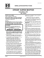
Figure 1. Design CV500 Flanged Valve with Type 1052

Actuator and Type DVC6020 Positioner

W8192-1 / IL

Figure 2. Design CV500 Wafer Valve with

Type 1066 Actuator

W5000-1 / IL

Instruction Manual

Form 5302
July 2006

CV500 Valve

Summary of Contents for Fisher 1052

Page 1: ...lve Flow Direction 19 Changing Actuator Mounting Style 20 Parts Ordering 20 Parts Kits 20 Parts List 21 Introduction Scope of Manual This instruction manual provides installation operation maintenance and parts ordering information for 3 through 12 inch Design CV500 Cam Vee Ballr rotary control valves Refer to separate manuals for information concerning the actuator and accessories Figure 1 Design...

Page 2: ...n to open extending actuator rod opens valve body Shaft Diameters 2 and Approximate Weights See table 3 1 The pressure temperature limits in this manual and any applicable standard limitations should not be exceeded 2 Shaft diameter and spline end must match available shaft diameter of actuator Description The Design CV500 Cam Vee Ball rotary control valve has a Vee Ballr style segmented ball in a...

Page 3: ...5 5 450 500 320 6 400 to 500 2 600 600 600 340 5 450 500 315 6 1 29_C 20_F for WCC steel valve body material 2 For hot water or steam service limit maximum temperature to 260_C 500_F 3 The pressure or temperature limits in this table or in any applicable code limitation should not be exceeded 4 Standard Fisher material offerings in Europe only 5 S17400 17 4PH SST shaft only 6 ASME SA 479 Grade SM ...

Page 4: ... valve body key 1 is to be stored before installation protect the flange mating surfaces and keep the valve body cavity dry and clear of foreign material 2 Install a three valve bypass around the control valve assembly if continuous operation will be necessary during inspection and maintenance of the valve 3 A Design CV500 valve is normally shipped as part of a control valve assembly with a power ...

Page 5: ...TOR POSITION ACTUATOR MOUNTING STYLE VALVE OPEN 1 2 3 4 NOTES 1 ARROW ON LEVER INDICATES DIRECTION OF ACTUATOR THRUST TO CLOSE VALVE 2 PDTC PUSH DOWN TO CLOSE PDTO PUSH DOWN TO OPEN 3 F FORWARD FLOW R REVERSE FLOW RIGHT HAND STYLE A PDTC STYLE B PDTO STYLE C PDTO STYLE D PDTC LEFT HAND F R F R F R F R C0741 IL ...

Page 6: ...rews Key 37 Valve Size N P PN Qty Bolt Size Bolt Length mm Overall Length mm 3 PN 10 40 4 M16 x 2 50 60 PN63 4 M20 x 2 5 60 73 PN100 4 M24 x 3 70 85 4 PN10 and 16 4 M16 x 2 50 60 PN25 and 40 4 M20 x 2 5 60 73 PN63 4 M24 x 3 70 85 PN100 4 M27 x 3 80 97 Valve Size Class Qty Bolt Size Bolt Length Inches Overall Length Inches 3 150 300 4 3 4 10 UNC 2 38 2 88 600 4 3 4 10 UNC 2 38 2 88 4 150 4 5 8 11 U...

Page 7: ...ther entirely of conductive packing rings graphite ribbon packing or partially of conductive packing rings a carbon filled PTFE female adaptor with PTFE V ring packing or a graphited composition packing ring with PTFE composition packing in order to electrically bond the shaft to the valve body Alternate shaft to valve body bonding is available for hazardous service areas where the standard packin...

Page 8: ...itions Packing Maintenance Key numbers refer to figure 11 for 3 through 8 inch sizes and to figure 12 for 10 and 12 inch sizes unless otherwise indicated Note For the ENVIRO SEAL packing system refer to the Parts List section for retrofit kits parts kits and individual parts see figures 13 and 14 Refer to separate ENVIRO SEAL instruction manual for maintenance instructions Standard ENVIRO SEAL pac...

Page 9: ... packing rings key 13 packing box ring key 17 and if used the lantern ring key 18 Do not scratch the valve shaft or packing box wall scratching these surfaces could cause leakage Clean all accessible metal parts and surfaces to remove particles that would prevent the packing from sealing 5 Whenever you are installing new packing be sure the ball key 2 is closed while you install and tighten the ne...

Page 10: ...NTS LEAKOFF ARRANGEMENT DOUBLE PACKING ARRANGEMENT PRESSURE SERVICE VACUUM SERVICE PRESSURE VACUUM SERVICE FOR PURGED BEARING CONSTRUCTION FOR PURGED BEARING CONSTRUCTION GRAPHITE RIBBON OR PTFE COMPOSITION PACKING PTFE V RING NOTES INCLUDES ZINC WASHERS KEY 28 FOR GRAPHITE RIBBON PACKING ONLY INCLUDED IN PTFE V RING PACKING SET KEY 13 FOR ONLY PTFE BOUND COMPOSITION PACKING TOP RING IS CONDUCTIVE...

Page 11: ...tected are the threads and inner surface of the retainer key 5 the sealing surfaces of the face seals key 8 the face seal grooves in the seat ring key 4 the shutoff surface of the seat ring and the face seal surface in the valve body A new retainer gasket key 11 is required whenever the retainer key 5 is removed Other parts that are in good condition can be reused Disassembly WARNING Refer to the ...

Page 12: ...parts and place them on a flat protected surface 7 Inspect the shutoff surface of the V notch ball If it is worn nicked or scratched proceed to the Replacing Ball Shaft and Bearings procedure in this manual If the parts are in good condition and do not require replacement continue to the Assembly procedure in this manual Assembly WARNING Seat ring installation requires that the ball key 2 remain i...

Page 13: ... with the correct shutoff surface facing the V notch ball and shaft The seat ring will cover the face seal installed in step 3 5 Place the second face seal key 8 on the seat ring key 4 6 Apply anti seize lubricant to the gasket surface in the valve body Install the gasket key 11 while making certain that the concave surface of the gasket is up hump surface of gasket down 7 Apply anti seize lubrica...

Page 14: ...sonal injury or property damage To avoid injury or damage carefully rotate the ball shaft assembly to a stable position in the valve body after the actuator is disconnected CAUTION To avoid increased leakage increased valve component wear or possible damage to the valve body key 1 ball key 2 drive shaft key 3 follower shaft key 38 and bearings keys 6 and 42 resulting from a sharp blow to the actua...

Page 15: ...ball to the drive shaft Remove the groove pin from the ball ear in the direction shown in figure 8 WARNING To avoid personal injury or damage to tools valve parts or other items resulting from the ball key 2 falling from the valve body support the ball to prevent it from falling as the drive shaft key 3 is being removed 10 Pull the drive shaft key 3 from the valve body If the shaft cannot be remov...

Page 16: ... allows easier installation of the V notch ball 1 Thoroughly clean the parts before assembly VALVE SIZE A MAX MIN L mm Inches mm Inches 3 27 8 27 4 1 094 1 078 165 6 50 4 34 1 33 7 1 344 1 328 165 6 50 6 42 1 41 7 1 656 1 641 197 7 75 8 42 1 41 7 1 656 1 641 229 9 00 10 48 4 48 0 1 905 1 890 229 9 00 12 57 8 57 4 2 275 2 260 260 10 25 Figure 9 Ram Dimension for Bearing Removal A3308 IL 2 If O ring...

Page 17: ...hole in the ball ear 7 For 3 through 8 inch sizes position the ball so that the larger hole is facing up away from the seat ring and retainer Determine the correct orientation of the V notch ball key 2 required by the specific installation orientation of the valve and the flow direction of the process fluid See figure 3 For 10 and 12 inch sizes determine the correct orientation of the V notch ball...

Page 18: ...use excessive force c Drive the expansion pin into the larger hole until the chamfered end of the pin reaches the inner lip of the smaller hole on the opposite side of the ball Closely observe the progress of the pin to avoid striking it after it has reached the lip of the smaller hole d Place the taper pin key 10 into the open end of the expansion pin Drive the taper pin into the expansion pin un...

Page 19: ...n rod or diaphragm rod 1 Mount the actuator following the instructions in the actuator instruction manual Refer to figure 3 to select actuator mounting style and position and to orient the actuator lever with the valve drive shaft key 3 2 For actuators with clamped levers pull the drive shaft key 3 by hand toward the packing key 13 so that the ball key 2 and thrust washer key 12 are tight against ...

Page 20: ...her Emerson Emerson Process Management Fisher nor any of their affiliated entities assumes responsibility for the selection use and maintenance of any product Responsibility for the selection use and maintenance of any product remains with the purchaser and end user Parts Kits Repair Kits Repair kits include recommended spares for standard and sealed bearing constructions VALVE SIZE INCHES REPAIR ...

Page 21: ...art Number 11 Retainer Gasket Use w metal seat construction only 316 SST 3 inch 19A5198X012 4 inch 19A5199X012 6 inch 19A5200X012 8 inch 19A6401X012 10 inch 12B6852X012 12 inch 12B3365X012 S31603 1 316L SST 3 inch 19A5198X032 4 inch 19A5199X042 6 inch 19A5200X032 8 inch 19A6401X032 10 inch 12B6852X022 12 inch 12A3365X022 12 Thrust Washer 2 req d for 17 7PH 1 1 req d for alloy 6 13 Packing Set w PT...

Page 22: ...X032 Packing washer key 28 14A9772X012 12 inch Ring graphite ribbon 1V949601652 Packing washer key 28 12B5927X012 14 Packing Follower 15 Packing Flange Stud 16 Packing Flange Nut Key Description Part Number 17 Packing Box Ring Use w all packing box constructions 316 SST 3 inch 16A6085X012 4 inch 16A6086X012 6 8 inch 16A6087X012 10 inch 12A9058X052 12 inch 12B3373X012 S31603 2 316L SST 3 inch 16A60...

Page 23: ...ion Manual Form 5302 July 2006 23 Figure 11 3 Through 8 Inch Design CV500 Valve 42B3374 A IL TCM SEAL DOUBLE PACKING SEALED BEARING NOTE MEASURE GAP HERE 1 APPLY LUB KEY NUMBERS NOT SHOWN ARE 28 30 31 33 36 37 130 AND 131 ...

Page 24: ...struction Manual Form 5302 July 2006 24 Figure 12 10 and 12 Inch Design CV500 Valve 42B5286 A IL NOTE MEASURE GAP HERE 1 APPLY LUB KEY NUMBERS NOT SHOWN ARE 28 30 31 33 36 37 130 AND 131 DOUBLE PACKING SEALED BEARING ...

Page 25: ...2 inch 13B8816X032 3 inch 13B8816X092 4 inch 13B8816X112 6 8 inch 13B8816X142 Key Description Part Number 106 Anti Extrusion Ring Composition graphite filled PEEK 1 2 req d Single PTFE packing w std packing box 1 inch 12B7054X012 1 5 2 inch 12B7406X012 3 inch 12B7442X012 4 inch 12B7454X012 6 8 inch 12B7466X012 Double PTFE packing w std deep pkg box 1 inch 12B7054X012 1 5 2 inch 12B7406X012 3 inch ...

Page 26: ...NGS SINGLE PTFE PACKING STANDARD DEPTH BOX DOUBLE PTFE PACKING STANDARD DEPTH PACKING BOX DOUBLE PTFE PACKING WITH LEAKOFF OPTIONAL DEEP PACKING BOX 14B0095 A 42B8445 B 42B8445 B 42B8445 B Figure 14 Typical ENVIRO SEALr Rotary Packing Arrangements with Graphite Packing STACKING ORDER OF GRAPHITE PACKING RINGS GRAPHITE PACKING STANDARD DEPTH BOX 14B0086 A 42B8445 B NOTES APPLY LUBRICANT THESE TWO S...

Page 27: ...2 4 Standard 1 19A3677X012 19A5187X012 19A3679X152 Sealed 19A3678X012 29A5188X012 6 Standard 1 19A4239X012 19A5190X012 19A4241X132 Sealed 19A4240X012 29A5191X012 8 Standard 1 19A3645X012 19A5193X012 19A3647X132 Sealed 19A3646X012 29A5194X012 1 Also use for purged bearing constructions Key 6 Follower Bearing for Size 10 and 12 Inch Valves VALVE SIZE INCHES BEARING TYPE BEARING MATERIAL S44004 440C ...

Page 28: ...rson Process Management Fisher nor any of their affiliated entities assumes responsibility for the selection use and maintenance of any product Responsibility for the selection use and maintenance of any product remains with the purchaser and end user EFisher Controls International LLC 1991 2006 All Rights Reserved Printed in USA ENVIRO SEAL Cam Vee Ball Vee Ball edisc and Fisher are marks owned b...

Reviews: