background image

www.Fisher.com

Fisher

 1051 and 1052 Size 33

Diaphragm Rotary Actuators

Contents

Introduction

1

. . . . . . . . . . . . . . . . . . . . . . . . . . . . . . . . .

Scope of Manual

1

. . . . . . . . . . . . . . . . . . . . . . . . . . . . .

Description

2

. . . . . . . . . . . . . . . . . . . . . . . . . . . . . . . . .

Specifications

3

. . . . . . . . . . . . . . . . . . . . . . . . . . . . . . .

Installation

3

. . . . . . . . . . . . . . . . . . . . . . . . . . . . . . . . . .

Actuator Mounting and Changing Actuator

Mounting

5

. . . . . . . . . . . . . . . . . . . . . . . . . . . . . . . .

F and G Mounting Adaptations

5

. . . . . . . . . . . . .

H Mounting Adaptation

7

. . . . . . . . . . . . . . . . . . .

J Mounting Adaptation

8

. . . . . . . . . . . . . . . . . . . .

1052 Spring Compression Adjustment

10

. . . . . . . . .

Initial Compression

10

. . . . . . . . . . . . . . . . . . . . . .

Stroking Range

11

. . . . . . . . . . . . . . . . . . . . . . . . .

Maintenance

11

. . . . . . . . . . . . . . . . . . . . . . . . . . . . . . . .

Mounting Adaptations

12

. . . . . . . . . . . . . . . . . . . . . .

Replacing Diaphragm

12

. . . . . . . . . . . . . . . . . . . . . . .

Replacing Diaphragm Plate, Diaphragm Rod,

Spring, and Spring Seat

13

. . . . . . . . . . . . . . . . . . . .

Changing Or Replacing Actuator Lever

16

. . . . . . . . .

Proximity Switches, Lever‐Operated Switches,

and Positioner

18

. . . . . . . . . . . . . . . . . . . . . . . . . . .

Installing the Cam 

18

. . . . . . . . . . . . . . . . . . . . . .

Installing Proximity Switches

19

. . . . . . . . . . . . . .

    Switches Indicating Bottom of Stroke

19

. .

    Switches Indicating Top of Stroke

19

. . . . . .

Installing Lever‐Operated Switch

19

. . . . . . . . . .

  Installing the Push Rod 

20

. . . . . . . . . . . . . . . .

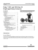
Figure 1. Fisher 1052 Actuator with CV500 Valve and
FIELDVUE™ DVC6200 Digital Valve Controller

W8192‐2

  Mounting Lever‐Operated Switch and

Adjustment

20

. . . . . . . . . . . . . . . . . . . . . . . . . .

Positioner Mounting

20

. . . . . . . . . . . . . . . . . . . . . . . .

Top‐Mounted Handwheel

20

. . . . . . . . . . . . . . . . . . . .

Locking Mechanism

21

. . . . . . . . . . . . . . . . . . . . . . . . .

Parts Ordering

23

. . . . . . . . . . . . . . . . . . . . . . . . . . . . . . .

Parts Kits

23

. . . . . . . . . . . . . . . . . . . . . . . . . . . . . . . . . . .

Parts List

23

. . . . . . . . . . . . . . . . . . . . . . . . . . . . . . . . . . .

Introduction

Scope of Manual

This instruction manual includes installation, adjustment, operation, maintenance, and parts information for the
Fisher 1051 and 1052 Size 33 diaphragm rotary actuators (figure 1). Mounting adaptations F, G, H, and J are included
in this manual. Instructions for the control valve, positioner, manual actuator, and other accessories are included in
separate manuals.

Instruction Manual

D101322X012

1051 and 1052 Size 33 Actuators

June 2017

Summary of Contents for Fisher 1051

Page 1: ...itches Indicating Bottom of Stroke 19 Switches Indicating Top of Stroke 19 Installing Lever Operated Switch 19 Installing the Push Rod 20 Figure 1 Fisher 1052 Actuator with CV500 Valve and FIELDVUE DVC6200 Digital Valve Controller W8192 2 Mounting Lever Operated Switch and Adjustment 20 Positioner Mounting 20 Top Mounted Handwheel 20 Locking Mechanism 21 Parts Ordering 23 Parts Kits 23 Parts List ...

Page 2: ...ods and Guides used with lever operated switches 40 to 82_C 6 40 to 180_F Travel Indication Graduated disc and pointer Pressure Connections Standard 1 4 NPT internal Optional J 1 2 or J 3 4 NPT internal Mounting Positions See figure 2 Approximate Weights 1051 20 kg 45 pounds 1052 21 kg 46 pounds 1 The pressure temperature limits in this manual and any applicable standard or code limitation for val...

Page 3: ... with flats is pinned to the lever and is used to couple the actuator to the operated equipment A second stub shaft may be installed on the opposite end of the lever for use as a wrench operated extension for emergency override or as a means for connecting a manual actuator see figure 14 Stub shafts are available in standard and reverse constructions see figure 12 to provide proper operation with ...

Page 4: ... A B A B A B CW CW NA NA B A Left Hand PDTC PDTO CCW CCW NA NA D C D C CW CW C D C D Left Hand Optional 2 PDTC PDTO CW CW NA NA C D NA NA NA NA NA NA NA NA 1 PDTC Push down to close and PDTO Push down to open 2 A left hand ball will be required for the NPS 3 through 12 Series B and the NPS 14 to 20 with or without attenuator Figure 2 Mounting Styles and Positions for Fisher 1051 and 1052 Actuators...

Page 5: ...ctuator and in figure 10 for the 1052 actuator 1 Proceed as appropriate If the Actuator is mounted on a valve body and it is necessary to change mounting style or position the actuator must first be separated from the valve body Proceed to the Disassembly portion of the Changing or Replacing Actuator Lever procedure observe all warnings perform steps 1 through 6 and return to step 2 which follows ...

Page 6: ...3 Actuator HOUSING COVER ASSEMBLY KEY 33 PROXIMITY SWITCHES MOUNTING POSITION FOR SWITCH INDICATING TOP OF STROKE ACTIVATED BY OUTER CAM YOKE MOUNTING BOSS UP TRAVEL STOP DOWN TRAVEL STOP MOUNTING POSITION FOR SWITCH INDICATING BOTTOM OF STROKE ACTIVATED BY INNER CAM W4738 7 Tighten the socket head cap screw which compresses the splined lever connection to the valve shaft see table 2 CAUTION When ...

Page 7: ... will be mounted on the housing cover assembly key 33 side or on the actuator housing boss side of the actuator Depending on the desired mounting style and position it may be necessary to move the operated equipment and travel indicator components to opposite sides of the actuator If so remove the travel indicator components the operated equipment and the mounting bracket if used Install the opera...

Page 8: ...emove the travel indicator components the valve shaft coupling key 80 for 1051 or key 90 for 1052 cap screws key 23 and the mounting yoke Install the mounting yoke in the desired position on the housing cover assembly or on the actuator housing boss See table 2 for recommended torque for the mounting cap screws Install the valve shaft coupling on the actuator stub shaft Install the travel indicato...

Page 9: ...or counterclock wise for actuator housing construction Style A in the lever when viewed from the splined end of the actuator shaft 30 degrees is one spline tooth for 9 5 12 7 and 15 9 mm 3 8 1 2 and 5 8 inch valve shafts and two spline teeth for 19 1 mm 3 4 inch valve shafts Figure 4 Valve Shaft Coupling for the J Mounting Adaptation A3253 19A1465 B NOTES FOR USE WITH J MOUNTING ADAPTATION COUPLIN...

Page 10: ...ted equipment must be removed or otherwise disengaged from the actuator Refer to the applicable steps given under the appropriate mounting adaptation in the Actuator Mounting and Changing Actuator Mounting procedure To gain access to the spring adjusting screw either the spring adjuster cover key 117 or the switch mounting plate key 59 must be removed If externally mounted switches are used remove...

Page 11: ...g pressure at which the actuator begins to stroke and the pressure at which the actuator reaches full travel To gain access to the spring adjusting screw either the spring adjuster cover key 117 or the switch mounting plate key 59 must be removed If externally mounted switches are used remove them as an assembly by removing the cap screws key 75 figure 16 and the switch mounting plate key 1 figure...

Page 12: ...o the actuator Be sure the actuator cannot suddenly open or close the valve D Use bypass valves or completely shut off the process to isolate the valve from process pressure Relieve process pressure from both sides of the valve Drain the process media from both sides of the valve D Vent the power actuator loading pressure and relieve any actuator spring precompression D Use lock out procedures to ...

Page 13: ...phragm case key 1 Replace the cap screws and nuts keys 5 and 6 which secure the upper diaphragm case to the actuator housing Tighten the nuts in an alternating fashion see table 2 CAUTION When adjusting the travel stop for the closed position of the valve ball or disc refer to the appropriate valve body instruction manual for detailed procedures Undertravel or overtravel of many valve types may re...

Page 14: ...screw keys 74 and 14 and lower thrust washer key 72 Note At this stage of disassembly it may be determined that further disassembly is not necessary If separation of the diaphragm rod from the lever is not warranted proceed to the Assembly portion of this procedure 4 To gain access to the cap screw key 18 which secures the diaphragm rod to the lever the housing cover assembly key 33 must be remove...

Page 15: ...et head cap screw through the diaphragm plate key 4 and into the diaphragm rod key 10 Tighten the cap screw four or five turns 3 Install the spring seat with spring adjusting screw for the 1052 actuator spring and upper thrust washer 4 Insert the diaphragm plate diaphragm rod assembly into the spring barrel Make sure that the notch in the diaphragm rod is oriented according to the view shown in fi...

Page 16: ...Install the cover plate or switch mounting plate key 59 with cap screws key 60 If switches are used observe the marks made during removal of the cover plate 12 Install the spring adjuster cover key 117 or the switch mounting plate key 1 figure 16 with the appropriate cap screws 13 Install the travel indicator key 37 if removed 14 If the actuator was removed from the valve body refer to the appropr...

Page 17: ...y to loosen the hex nuts key 77 figure 16 and slide the switches away from the actuator housing 3 If switches are used mark the position of the switch mounting plate key 59 on the actuator housing so it may be returned to the exact same position 4 Remove the cap screws key 60 and the cover plate or switch mounting plate key 59 If switches are used leave the push rod assemblies keys 169 and 170 fig...

Page 18: ...ith the lever Install the cap screw key 18 and tighten to the torque value in table 2 5 If an outer switch cam is used install the cam using the two machine screws spacers and retaining washers Note that the retaining washers help to keep all parts together as an assembly Observe the orientation shown in figure 7 6 If a positioner is used install the positioner cam with machine screws Be sure to o...

Page 19: ...ation shown in figure 7 and in the positioner instruction manual Follow the steps in the Installation section to reassemble the actuator and install the actuator on the valve body Installing Proximity Switches Key numbers referenced in the following procedures are shown in figure 15 unless otherwise specified Switches Indicating Bottom of Stroke 1 Apply inlet pressure to the diaphragm case key 1 f...

Page 20: ... rod guide and thereby reduce its clearance with the push rod head 7 Install the boot key 163 over the push rod and the push rod guide Mounting Lever Operated Switch and Adjustment 1 If used remove the cap screws and spring adjuster cover keys 21 and 85 for 1051 or keys 21 and 117 for 1052 2 Attach the switch mounting plate key 1 at this location with cap screws key 75 Tighten the cap screws to th...

Page 21: ... the disassembly portion of the Replacing Diaphragm procedure 2 Remove the cotter pin hex nut handwheel and locknut keys 247 54 51 and 137 Unscrew the stem key 133 out through the actuator end of the handwheel body key 142 3 Remove cap screws key 141 and separate the handwheel assembly from the upper casing 4 Check the condition of the O rings keys 138 and 139 replace them if necessary 5 If it is ...

Page 22: ...rotate the locking mechanism counterclockwise until it is stopped by the groove pin key 127 Attach the cover to the actuator with cap screws key 60 4 Attach mounting plate key 123 with cap screws key 21 5 Be sure the diaphragm rod is retracted fully This will be the locked position of the valve 6 Screw the threaded bolt into the cover until it contacts the actuator lever 7 Rotate the locking devic...

Page 23: ...parts Components that are not supplied by Emerson Automation Solutions should not under any circumstances be used in any Fisher valve because they may void your warranty might adversely affect the performance of the valve and could cause personal injury and property damage Parts Kits Key Description Part Number Retrofit Kits Kit provides parts to add a top mounted handwheel Kit number 1 includes t...

Page 24: ...ed steel 2 req d 55 Vent Screen zinc stainless steel 56 Warning Nameplate 59 Cover Plate painted steel 60 Cap Screw plated steel 4 req d 63 Washer plated steel 4 req d 71 For 1051 only Cap Screw plated steel Key Description 72 For 1052 only Thrust Washer nylon 2 req d 74 For 1052 only Spring Adjuster cast iron 74 For 1051 only lithium grease 76 For 1052 only 78 For 1052 only Cap Screw plated steel...

Page 25: ...Instruction Manual D101322X012 1051 and 1052 Size 33 Actuators June 2017 25 Figure 10 Fisher 1052 Size 33 Actuator with F or G Mounting Adaptation 50B3571 F APPLY LUB ...

Page 26: ...d and Reverse Constructions of the Stub Shaft Used for H Mounting Adaptations 50B1581 B STANDARD CONSTRUCTION REVERSE CONSTRUCTION Parts Used For H Mounting Adaptations figure 11 Key Description Parts For Use With 1051 Actuators Only 77 Stub Shaft steel 1 req d for valve mounting 2 req d for use with manual actuator or wrench operated extension 79 Pin steel 1 req d for each stub shaft Parts For Us...

Page 27: ...KEY 1052 KEY Parts Used For J Mounting Adaptations figure 13 Key Description Parts For Use With 1051 Actuators Only 44 Pin steel for coupler 79 Pin steel for stub shaft 80 Coupling steel 81 Woodruff key steel For 3 8 1 2 inch valve shaft size For 5 8 inch valve shaft size 87 Stub shaft steel Key Description Parts For Use With 1052 Actuators Only 89 Pin steel for stub shaft 90 Coupling steel 91 Woo...

Page 28: ... LEVER KEY 27 SEE PARTS LIST NO TRAVEL INDICATOR COMPONENTS USED KEYS 35 36 37 AND 38 FIGURES 8 AND 9 1 2 3 2 2 1 3 Parts Used For Wrench Operated Extension and For Manual Actuator Installation On All Mounting Adaptations figure 14 Key Description 37 Travel Indicator stainless steel not used with manual actuator Parts For Use With 1051 Actuators Only 77 Stub shaft steel 78 Retaining Ring steel for...

Page 29: ...1534 C SECTION A A A A Proximity Switch Mounting Accessories figure 15 Key Description 7 Proximity Switch 117 Machine Screw for Inner Cam plated steel 119 Machine Screw for Outer Cam plated steel 132 Spacer for Outer Cam steel 2 req d 144 Retaining Washer carbon steel 2 req d 170 Switch Cam painted steel 1 req d for each 171 Plug plastic used in single switch ...

Page 30: ...ver steel for Namco switch only 75 Cap Screw plated steel 2 req d 77 Hex Nut plated steel 2 req d for each 78 Hex Nut plated steel 1 req d for each 117 Machine Screw for Inner Cam plated steel 119 Machine Screw for Outer Cam plated steel 129 Mounting Bracket steel 1 req d for each 132 Spacer for Outer Cam steel 2 req d 144 Retaining Washer carbon steel 2 req d 154 Washer plated steel 2 req d for e...

Page 31: ...ted Handwheel figure 17 Key Description 51 Handwheel cast iron 54 Hex Nut Slotted steel 133 Stem bronze 135 Pusher steel Key Description 137 Hex Nut steel 138 O ring NBR 139 O ring NBR 140 Groove Pin steel 141 Cap Screw plated steel 6 req d 142 Body cast iron 241 Lithium grease 244 Anti seize lubricant 247 Cotter Pin SST Recommended spare parts ...

Page 32: ... available upon request We reserve the right to modify or improve the designs or specifications of such products at any time without notice E 1986 2017 Fisher Controls International LLC All rights reserved Fisher FIELDVUE Vee Ball and FISHTAIL are marks owned by one of the companies in the Emerson Automation Solutions business unit of Emerson Electric Co Emerson Automation Solutions Emerson and th...

Reviews: